
Datasheet

JW
6
ds_61B08_en_jw: 040713D
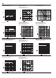
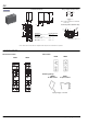
ACCESSORIES
JW 2 Form A and 2 Form C
CAD Data
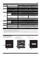
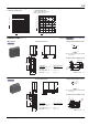
External dimensions
20
.787
0.4
.016
3.6
.142
0.5
.020
0.5
.020
0.3
.012
0.3
.012
1.1
.043
1.3
.051
5
5
.197
.197
15
.591
28.6
1.128
7.5
.295
12.8
.504
0.8
.031
Note: JW 2 Form A is as shown in the diagram above except the N.C. terminals are not present.
Wiring diagram (Bottom view)
Note: Terminal numbers are not indicated
on the relay.
PC board pattern (Bottom view)
Tolerance: 0.1 .004
COM
N.O.
N.C.
4
3
2
5
6
7
Coil
18
Relay outline
7.5
.295
1.3
.051
5
.197
20
.787
6-1.5 dia.
6-.059 dia.
Dimension:
Less than 1mm .039inch:
Min. 1mm .039inch
less than 3mm .118 inch:
Min. 3mm .118 inch:
General tolerance
0.1 .004
0.2 .008
0.3 .012
DIN terminal sockets PCB sockets
Retaining springs
NO
14
21
BA
NC 12
NO 14
21
BA
NC 12
COIL
COM
24
COIL
11
COM
22
JW1SI JW2SI
JW1PI JW2PI
JWHFE
for DIN sockets
JWHFI
for print sockets
h (relay height) = 20.4 mm