INSTALLATION INSTRUCTIONS Split System Air Conditioner $/09 (08 *54+0:054,8 ;9,9 :/, 8,-80.,8(4: " NOTE >:,84(2 +0(3,:,8 5- 9,8<0*, 658: " Contents Page IMPORTANT! Please Read Before Starting .................................. 2 Model Combinations 1. GENERAL .......................................................... 4 1-1. Tools Required for Installation (not supplied) 1-2. Accessories Supplied with Unit 1-3. Optional Copper Tubing Kit 1-4.
IMPORTANT! Please Read Before Starting When Transporting Be careful when picking up and moving the indoor and outdoor units. Get a partner to help, and bend your knees when lifting to reduce strain on your back. Sharp edges or thin aluminum fins on the air conditioner can cut your fingers. This air conditioning system meets strict safety and operating standards. As the installer or service person, it is an important part of your job to install or service the system so it operates safely and efficiently.
Others 8VH WKH IODUH PHWKRG IRU FRQQHFWLQJ WXELQJ $SSO\ UHIULJHUDQW OXEULFDQW WR WKH PDWFKLQJ VXUIDFHV RI the flare and union tubes before connecting them, then tighten the nut with a torque wrench for a leakfree connection. CAUTION &KHFN FDUHIXOO\ IRU OHDNV EHIRUH VWDUWLQJ WKH WHVW UXQ 9HQWLODWH DQ\ HQFORVHG DUHDV ZKHQ LQVWDOOLQJ RU WHVWLQJ the refrigeration system. Escaped refrigerant gas, on contact with fire or heat, can produce dangerously toxic gas.
1. General 6. 7. 8. 9. 10. 11. 12. 13. 14. 15. This booklet briefly outlines where and how to install the air conditioning system. Please read over the entire set of instructions for the indoor and outdoor units and make sure all accessory parts listed are with the system before beginning. 1-1. Tools Required for Installation (not supplied) 1. Standard screwdriver 2. Phillips head screwdriver 3. Knife or wire stripper 4. Tape measure 5.
1-5. Additional Materials Required for Installation 1. 2. Indoor unit Refrigeration (armored) tape Insulated staples or clamps for connecting wire (See local codes.) Putty Refrigeration lubricant Clamps or saddles to secure refrigerant tubing 3. 4. 5. Drain hose 2. Installation Site Selection Outside drainage 2-1. Indoor Unit Fig.
2-2. Outdoor Unit NO AVOID: Heat source DO: Outdoor unit choose a place as cool as possible. choose a place that is well ventilated. install in a location where at least two sides are unobstructed, so that the flow of air at the intake port or exhaust port is not blocked, and so that sufficient space is ensured for maintenance to be carried out without trouble. In general the top also must be unobstructed. (Fig.
2-2-1. Installing the Unit in an Area with High Winds and in a Snowy Area 4 25*(:0549 =0:/ /0./ =04+9 ( =04+ 6855- +;*: 08 +09*/(8., 9/5;2+ ), -0::,+ (4+ +08,*: ,>659;8, :5 :/, =04+ 9/5;2+ ), (<50+,+ (9 3;*/ (9 65990)2, 0. , 08E +09*/(8., 4 8,.0549 =0:/ 90.40-0*(4: 945=-(22 :/, 5;:+558 ;40: 9/5;2+ ), 685<0+,+ =0:/ ( 62(:-583 (4+ 945= 6855- +;*: 0. - 08 +09*/(8., Countermeasures against snow and wind 4 8,.0549 =0:/ 945= (4+ 9:854. =04+ :/, -5225=04.
2-2-3.
Required space around the outdoor unit - :/, =04+ 6855- +;*: 09 ;9,+ :/, 96(*, 9/5=4 ),25= 3;9: ), 9,*;8,+ (85;4+ :/, 5;:+558 ;40: - :/, ;40: 09 ;9,+ =0:/5;: :/, 8,7;08,+ 96(*, ( 685:,*:0<, +,<0*, 3(? (*:0<(:, 68,<,4:04. :/, ;40: -853 56,8(:04. 04 58 358, 04 58 358, #04.
2-2-4.
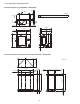
Reference diagram for snow-proof duct Space requirements for setting CU-KE30NKU, CU-KE36NKU with STK-BDV80E [Obstacle to the front of unit] [Obstacle to the rear of unit] $56 09 56,4 $56 09 56,4 #04.2, ;40: 049:(22(:054 04 58 358, 04 58 358, 04 58 358, #04.
[Obstacles to the front and rear of unit] $/, :56 (4+ )5:/ 90+,9 3;9: 8,3(04 56,4 0:/,8 :/, 5)9:(*2, :5 :/, -854: 58 :/, 5)9:(*2, :5 :/, 8,(8 3;9: ), 45 :(22,8 :/(4 :/, /,0./: 5- :/, 5;:+558 ;40: 04 58 358, 04 58 358, 04 58 358, #04.
3. How to Install the Indoor Unit 3-1. Remove the Rear Panel from the Unit (1) Remove and discard the set screw on the rear panel. (Fig. 6) (2) Press the 2 marks on the frame cover and disengage the stationary tabs from the frame. (Fig. 7a) Set screw only for transportation Fig. 6 (3) Remove the rear panel by grasping the sections shown in Fig. 7b and pulling it in the direction shown by the arrow. Rear panel NOTE Tubing can be extended in 6 directions as shown in Fig. 8.
(4) Using a sabre saw, key hole saw or hole-cutting drill attachment, cut a hole in the wall. See Table 4 and Fig. 10. NOTE Hole should be made at a slight downward slant to the outdoor side. Table 4 Indoor side Hole Dia. Outdoor side 3-5/32" (80 mm) (5) Measure the thickness of the wall from the inside edge to the outside edge and cut PVC pipe at a slight angle 1/4" (6 mm) shorter than the thickness of the wall. (Fig. 11) Fig.
Front panel 3-4. Removing and Installing the Grille Arm Basically, these models can be installed and wired without removing the grille. If access to any internal part is needed, follow the steps as given below. How to remove the grille (1) Open the front panel until it is nearly horizontal, grasp the sections near the front panel arms on both sides, and then remove the panel by pushing the arms towards the outside while pulling the panel towards you.
3-5. Shape the Indoor Side Tubing (1) Arrangement of tubing by direction 8(3, a) Right or left tubing Cut out the corner of the right/left frame with a hacksaw or the like. (Figs. 20 and 21) ,-: :;)04. 5;:2,: b) Right-rear or left-rear tubing In this case, the corner of the frame need not be cut. (2) To mount the indoor unit on the rear panel: Fig. 20 Hang the 3 mounting slots of the unit on the upper tabs of the rear panel. (Fig. 22) Frame 3-6.
3-7. Wire Size and Length Regulations on wiring diameter differ from locality to locality. For field wiring requirements, please refer to your local electrical codes. Carefully observe these regulations when carrying out the installation. NOTE Refer to the wiring system diagram (Fig. 23) for the meaning of (A), (B), and (C) in Table 5. Refer to your local codes or in the absence of local codes see the National Electric Code: ANSI/NFPA70.
3-8. Wiring Instructions for Inter-unit Connections (1) Insert the inter-unit wiring (according to local codes) into the through-the-wall PVC pipe. Run the wiring toward the indoor side allowing approx. 10" (25 cm) to extend from the wall face. (Fig. 24) ",(8 6(4,2 '(22 2(9:0* *5<,8 (2) Grasp both ends of the front panel, push the arms towards the outside, and remove the front panel by opening it towards the front and pulling it towards you.
WARNING Loose wiring may cause the terminal to overheat or result in unit malfunction. A fire hazard may also exist. Therefore, be sure all wiring is tightly connected. When connecting each power wire to the corresponding terminal, follow the instructions “How to connect wiring to the terminal” and fasten the wire securely tight with the fixing screw of the terminal plate. STRIP SIZE How to connect wiring to the terminal 9/32" (7 mm) (ACTUAL SIZE) a) For Indoor Unit Fig.
3-9. Mounting (1) To install the indoor unit, mount the indoor unit onto the 3 tabs on the upper part of the rear plate. (2) Hold down the air discharge outlet and press the lower part of the indoor unit until it clicks to securely fasten to the 2 tabs on the lower part of the rear plate. (Fig. 33) Push NOTE For tubing, choose either the right or left tubing direction and follow the steps below. Also, extend the support on the back of the indoor unit as a stand to make your work easier. (Fig. 34) Fig.
Left-side tubing (1) Lead the tubing and drain hose through the wall, allowing sufficient length for connection. Then bend the tubing using a tube bender to make the attachment. (Fig. 38) Rear panel Hole in wall (2) Switch the drain hose and drain cap. Switching drain hose and drain cap Bent part (a) Locate the drain hose and the drain cap. (Fig. 39) Narrow tube Wide tube Fig. 38 (b) Remove the screw fastening the drain hose on the right side, and pull out the drain hose to remove it. (Fig.
To unmount indoor unit Press the 2 marks on the lower part of the indoor unit and unlatch the tabs. Then lift the indoor unit and unmount. (Fig. 42) 3-10. Frame Fastening Method (1) Remove the screw cover on the bottom surface. (Fig. 43) (2) Fasten the frame to the rear panel using the 2 supplied tapping screws 5/32" x 13/32" (4 x 10 mm). (Fig. 43) NOTE Push Under normal conditions, the installation design calls for a less than 3/32" (2 mm) gap between the air conditioner unit and the wall.
4. How to Install the Outdoor Unit 496,*:054 6(4,2 First refer to Section 2. Installation Site Selection. 4-1. Wiring Instructions for the Outdoor Unit Regulations on wire size differ from locality to locality. For field wiring requirements, please refer to your local electrical codes. Make sure that the installation fully complies with all local and national regulations. #*8,= (1) Remove the 3 screws from the inspection panel. (Fig.
5. Refrigerant Tubing Deburring After Before 5-1. Use of the Flaring Method Many of the conventional split system air conditioners employ the flaring method to connect refrigerant tubes which run between indoor and outdoor units. In this method, the copper tubes are flared at each end and connected with flare nuts. 5-2. Flaring Procedure with a Flare Tool (1) Cut the copper tube to the required length with a tube cutter. It is recommended to cut approx.
5-4. Connecting Tubing between Indoor and Outdoor Units a) b) Torque wrench Tightly connect the indoor side refrigerant tubing extended from the wall with the outdoor side tubing. (Fig. 52) Spanner Indoor unit To fasten the flare nuts, apply specified torque as: Table 6 Outdoor unit Tube Dia. Nut Tightening Torque 1/4" (6.35 mm) 21/32" (17 mm) Approx. 120 – 160 lbs·in (140 – 180 kgf·cm) 3/8" (9.52 mm) 7/8" (22 mm) Approx. 300 – 360 lbs·in (340 – 420 kgf·cm) 1/2" (12.
6. Air Purging Indoor unit Air and moisture remaining in the refrigerant system have undesirable effects as indicated below. Therefore, they must be purged completely.
(5) With the vacuum pump still running, close the “Lo” knob of the manifold valve. Then stop the vacuum pump. 90 (1/4 turn) Vacuum hose to manifold valve (6) With the hex wrench, turn the valve stem on the narrow tube service valve counter-clockwise by 90 degrees (1/4 turn) for 10 seconds, and then turn the stem clockwise to close it again. (Fig. 58) CAUTION Hex wrench Be sure to completely insert the hex wrench before attempting to turn the valve.
How to Test Run the Air Conditioner After turning on the power of the air conditioner, use the remote controller and follow the steps below to conduct the test run. (1) Set the remote controller in Test Run mode. (Fig. 59a) a) Press and hold the QUIET button and the 1HR. TIMER button. b) Then press and hold the ACL (Reset) button with a pointed object such as the tip of a pen. After 5 seconds, release the ACL button first. !% $ );::54 c) Then release the QUIET and 1HR. TIMER buttons.
Basic Functions of the Service Valves The basic functions of the service valves are given in Table 8 below. Table 8 Narrow Tube Service Valve (2-Way) Action Wide Tube Service Valve (3-Way) O-ring CLOSED Valve cap Stem Shipping Fully OPEN Operating and test running the air conditioner Fully OPEN Measuring pressure * and gas charging CLOSED Air purging with * The service port on the wide tube service valve uses a Schrader core valve to access the refrigerant system.
Service Valve Connections ( $,3658(8? *544,*:054 #*8,= 04 @ :;849 )? /(4+ 0. * ) $5 -(9:,4 :/, -2(8, 4;:9 (662? 96,*0-0,+ :587;, (9 $()2, (4+ 0. + $587;, =8,4*/ Table 9 Tube Dia. Nut Fig. 60c Tightening Torque 1/4" (6.35 mm) 21/32" (17 mm) Approx. 120 – 160 lbs·in (140 – 180 kgf·cm) 3/8" (9.52 mm) 7/8" (22 mm) Approx. 300 – 360 lbs·in (340 – 420 kgf·cm) 1/2" (12.70 mm) 1-1/32" (26 mm) Approx. 430 – 480 lbs·in (490 – 550 kgf·cm) 5/8" (15.
8. Address Switch Tab 8-1. Address Setting of the Remote Controller The address can be set in order to prevent interference between remote controllers when 2 indoor units are installed near each other. The address is normally set to “A.” To set a different address, it is necessary to change the address on the second remote controller. Fig. 62 NOTE Once changed, you cannot restore the original address setting of the air conditioner. (1) Switch on the power source.
DC1111-0