
User manual


4.3 Analog Output Unit (FP0R-DA4)
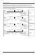
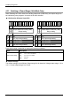
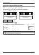
Sample program (Switching output range: For CH0/CH1)
The following program shows the case that the output ranges of CH0 and CH1 of the first
expansion analog input unit is set.
[ F0 MV , H30 , WY2 ]
R0
①
( )
DF
< RST >
< RST >
Y2E
Y2F
②
[ F0 MV , H30 , WY3
]
R1
①
( )
DF
< RST >
< RST >
Y3E
Y3F
③
④
⑤
⑥
⑦
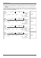
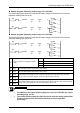
Sample program (Switching output range: For CH2/CH3)
The following program shows the case that the output ranges of CH2 and CH3 of the first
expansion analog input unit is set.
[ F0 MV , H30 , WY2 ]
R2
①
( )
DF
< SET >
< SET >
Y2E
Y2F
②
[ F0 MV , H30 , WY3 ]
R3
①
( )
DF
< SET >
< SET >
Y3E
Y3F
③
④
⑤
⑥
⑦
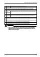
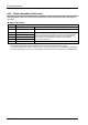
①
Input a constant for specifying an output
range.
H30
-10 to +10V / 0~20mA
H31
-5 to +5V / 4~20mA
H32 0 to 10V
H33 0 to 5V
②
WY2 Set it for switching the output range of CH0 or HC2.
③
WY3 Set it for switching the output range of CH1 or HC3.
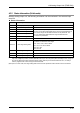
④
Y2E
Output data switching flags for even numbered channels. When Y2E/Y2F is OFF, the output
range of CH0 is set. When Y2E/Y2F is ON, the output range of CH2 is set.
⑤
Y2F
⑤
Y3E
Output data switching flags for odd numbered channels. When Y3E/Y3F is OFF, the output range
of CH1 is set. When Y3E/Y3F is ON, the output range of CH3 is set.
⑦
Y3F
KEY POINTS
• For CH0/CH1, the output switching flags are reset. For CH2/CH3, the output
switching flags are set.
• The output switching flags (bit F/bit E) are also used for setting output data.
Create a program not to overwrite each other during an operation
processing.
4-21