
User manual

5-153
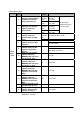
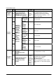
Setting the number of timers and counter (system register 5)
Timers and counters share the same area. If the method of dividing the area is changed, the number of
timers and counters will also change.
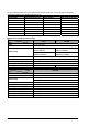
Type
Total point
numbers
Default value of
system register 5
Timer Counter
FP2 1,024 points 1000
1000 points
(No. 0 to 999)
24 points
(No. 1000 to 1023)
FP2SH/FP10SH 3,072 points 3000
3000 points
(No. 0 to 2999)
72 points
(No. 3000 to 3071)
For FP2/FP2SH, set the system registers 5 and 6 to the same value. This sets the timer to a non-hold
type and counter to a hold type.
By setting system register 5 to “0”, the whole area becomes the counter. Also, by setting it to the value 1
higher than the last number, the whole area becomes the timer.
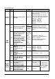
Hold type area starting address (system registers 6 to 13)
Set each relay and register to a hold type or non-hold type.
For normal situations, set the system registers 5 and 6 to the same value. This sets the timer to a non-
hold type and counter to a hold type.
By setting this value to the first number, the whole area becomes hold type. Also, by setting it to the
valeu 1 higher than the last number, the whold area becomes non-hold type.
The relays and registers for links not specified in the send area of system registers 40 to 55 are non-hold
type regardless of what is set here.