
User manual


Basic Instructions
2 − 16
Outline Leading edge detection and trailing edge detection output
The result of processing is output to the pulse relay for one scan only.
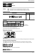
Program example
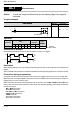
Ladder
Diagram
Boolean
Ladder Diagram
Address Instruction
0
X0
P0
P1
3
X1
Leading edge Out
Trailing edge Out
0
1
3
4
ST X 0
OT↑ P0
ST X 1
OT↓ P1
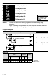
Operands
Instruction
Relay
Timer/Counter
Contact
Index
modifier
Instruction
X Y R L P E T C
modifier
OT↑ N/A N/A N/A N/A A N/A N/A N/A A
OT↓ N/A N/A N/A N/A A N/A N/A N/A A
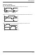
Explanation of example
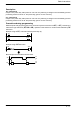
Output to pulse relay “P0” takes place for one scan only following a change in X0 from off to on.
X0
P0
One scan
on
off
on
off
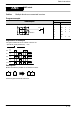
Output to pulse relay “P1” takes place for one scan only following a change in X1 from on to off.
X1
P1
One scan
on
off
on
off
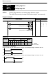
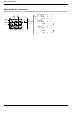
OT
OT
Leading edge Out
Trailing edge Out
↑
↓
A
:
A
vailable
N/A: Not Available