
User manual


Basic Instructions
2 − 133
Outline This changes the settings entered for the system registers of the PLC
link function, in accordance with the specified data.
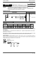
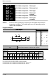
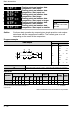
Program example
Ladder
Diagram
Boolean
Ladder Diagram
Address Instruction
S
Trigger
D2D1
SYS2,
10
R0
DT0, K40, K47
10
11
ST R 0
SYS2
DT 0
K40
K47
S Starting number of the area in which 16−bit data is stored
D1 Starting number of the system registers being specified (K40 to K47)
D2 Ending number of the system registers being specified (K40 to K47)
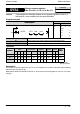
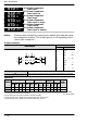
Operands
O
p
erand
Relay Timer/Counter Register
Index
register
Constant
Index
modifier
Operand
WX WY WR WL SV EV DT LD FL I K H
modifier
S N/A N/A N/A N/A N/A N/A A N/A N/A N/A N/A N/A N/A
D1 N/A N/A N/A N/A N/A N/A N/A N/A N/A N/A A N/A N/A
D2 N/A N/A N/A N/A N/A N/A N/A N/A N/A N/A A N/A N/A
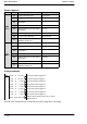
Description
The contents of system registers No. 40 to No. 47 are changed to the contents of the data registers starting
with the number specified by [S].
Note) With the FP0R, the FPΣ 32k and the FP−X, the contents of system registers No. 50 to No. 57 are also
changed.
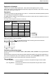
FPΣ/FP−X/FP0R
SYS2
Availability
FPΣ/FP−X/FP0R
Change system registers
(No. 40 to No. 47, No. 50 to No. 57)
A
:
A
vailable
N/A: Not Available