
User manual


High−level Instructions
3 − 18
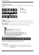
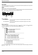
Explanation of example
The data at bit position 4 in data register DT20 is copied to bit position 12 in data register DT10 when trigger
R0 turns on.
Bit position
DT10
12
0
····
Bit position
·····
DT20
15
110
12
0
11
110
8
1
7
000
4
1
3
010
0
1
Source [S]
R0: on
········
15
000
11
010
8
0
7
110
4
1
3
001
0
0
Destination [D]
···
Bit position
·····
DT10
15
000
12
1
11
010
8
0
7
110
4
1
3
001
0
0
Destination [D]
n:HC04
Source
bit position 4
Destination
bit position 12
“F5 (BTM)”
execution
Description
A single bit in the 16-bit data or the 16-bit equivalent constant specified by S is copied to a bit of the 16-bit area
specified by D, as specified by n.
With the FP2SH and FP10SH, it is possible to transfer the contents of multiple bits as a single transfer.
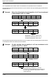
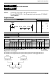
How to specify n
The “n” specifies the source and destination bit positions using hexadecimal data as follows:
n:H □□□
Bit position of source “S” (set range: H0 to HF)
Bit position of destination “D” (set range: H0 to HF)
Number of transfer bits
Range other than the above: “0” should be specified.
FP2 (Ver. 1.03 and subsequent versions), FP2SH and FP10SH only
Range: From 0 to F can be specified (refer to next page).
Bit position specification for S and D
Bit position 15 14 13 12 11 10 9 8 7 6 5 4 3 2 1 0
Set value HF HE HD HC HB HA H9 H8 H7 H6 H5 H4 H3 H2 H1 H0
For example, when bit position 10 is specified, “HA” should be specified.
If bit position 4 of S is being transferred to bit position 12 of D, n = HC04.
Flag conditions
・Error flag (R9007): Turns on and stays on when the area specified using the index modifier
exceeds the limit.
・Error flag (R9008): Turns on for an instant when the area specified using the index modifier
exceeds the limit.