
User manual

High−level Instructions
3 − 35
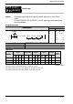
Outline Reads data from the F–ROM area.
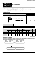
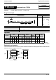
Program example
Ladder
Diagram
Boolean Non-ladder
Ladder Diagram
Address Instruction
10
F12 ICRD , K 0 , K10 , DT0
S1
D
Trigger
S2
R0
10
11
ST R 0
F 12 (ICRD)
K0
K10
DT 0
S1 Constant for specifying the starting address of F–ROM (for source data)
S2 32−bit equivalent constant or lower 16−bit area of 32−bit data for specifying
number of words to be read
D Starting 16−bit area for storing data read from F–ROM (for destination)
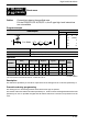
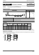
Operands
O
p
erand
Relay Timer/Counter Register
Index
register
Constant
Index
modifier
Operand
WX WY WR WL SV EV DT LD FL I K H
modifier
S1 N/A N/A N/A N/A N/A N/A N/A N/A N/A N/A A N/A N/A
S2 N/A N/A N/A N/A N/A N/A N/A N/A N/A N/A A N/A N/A
D N/A N/A N/A N/A N/A N/A A N/A N/A N/A N/A N/A N/A
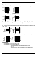
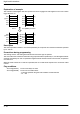
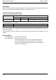
Explanation of example
10 blocks of data stored in blocks 0 to 9 of the F–ROM are transferred to data registers DT0 to DT20479 when
execution condition (trigger) R0 turns on.
0
2048
4096
18432
[S1] 0
F–ROM area
[D]
Address
(Block)
1
2
9
Data register DT
[S2]
2,048 words
2,048 words
2,048 words
2,048 words
FPΣ/FP−X/FP0R
F12
Availability
FPΣ/FP−X/FP0R
Data read from F–ROM
(ICRD)
A: Available
N/A: Not Available