
User manual

High−level Instructions
3 − 59
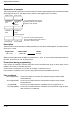
Outline Adds two 16-bit data items.
For the FP0R/FPΣ/FP−X/FP0/FP−e, the P type high−level instruction
“P20 (P+)” is not available.
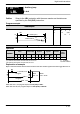
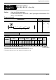
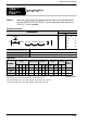
Program example
Ladder
Diagram
Boolean
Ladder Diagram
Address Instruction
10
F20 +, DT 1 , DT 10
S
D
Trigger
R0
10
11
ST R 0
F20 (+)
DT 1
DT 10
S 16-bit equivalent constant or 16-bit area (for addend)
D 16-bit area (for augend and result)
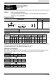
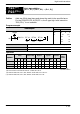
Operands
Operand
Relay Timer/Counter Register
Index
register
Constant
Inde
x
Operand
WX WY WR
WL
(*1)
SV EV DT
LD
(*1)
FL
(*2)
IX
(*3)
IY
(*4)
K H
Index
modifier
S A A A A A A A A A A A A A A
D N/A A A A A A A A A A A N/A N/A A
(*1) This cannot be used with the FP0 and FP−e.
(*2) This cannot be used with the FP0, FP−e, FP0R, FPΣ, FP−X.
(*3) With the FP0R, FPΣ,FP−X, FP2, FP2SH, and FP10SH, this is I0 to IC.
(*4) With the FP0R, FPΣ,FP−X, FP2, FP2SH, and FP10SH, this is ID.
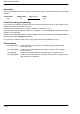
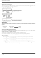
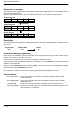
Explanation of example
The contents of data register DT10 and data register DT1 are added together when trigger R0 turns on.
When the decimal number 4 is in DT1 and the decimal number 8 is in DT10, as shown below.
····
Bit position
·····
DT10
15
000
12
0
11
000
8
0
7
000
4
0
3
100
0
0
Augend [D]: K8
····
Bit position
·····
DT1
15
000
12
0
11
000
8
0
7
000
4
0
3
010
0
0
Addend [S]: K4
····
Bit position
·····
DT10
15
000
12
0
11
000
8
0
7
000
4
0
3
110
0
0
Result [D]: K12
+
F20
P20
16-bit data addition
[D+S → D]
(+)
(P+)
A: Available
N/A: Not Available