
User manual


High−level Instructions
3 − 100
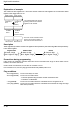
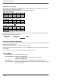
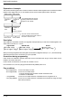
Explanation of example
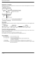
The contents of data register DT10 and data register DT20 are added together when trigger R0 turns on. The
added result is stored in data register DT30.
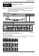
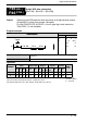
When H (BCD) 8 is in DT10 and H (BCD) 4 is in DT20, as shown below.
7
····
Bit position
·····
DT10
15
000
12
0
11
000
8
0
7
000
4
0
3
100
0
0
Augend [S1]: H8 (BCD)
····
Bit position
·····
DT20
15
000
12
0
11
000
8
0
7
000
4
0
3
010
0
0
Addend [S2]: H4 (BCD)
····
Bit position
·····
DT30
15
000
12
0
11
000
8
0000
4
1
3
001
0
0
Result [D]: H12 (BCD)
+
BCD H code
0008
BCD H code
0004
BCD H code
0012
(Addition)
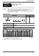
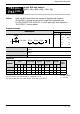
Description
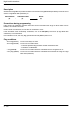
The 4-digit BCD equivalent constants or 16-bit areas for 4-digit BCD data specified by S1 and S2 are added
together. The added result is stored in D.
Augend data Result
(S1) (D)+ (S2)
Addend data
Precautions during programming
If the result of an arithmetic operation instruction does not fall within the range of values which can be
handled, an overflow will result.
Under normal circumstances, do not allow an overflow to occur.
If the calculated result accidentally overflows, use of the F43 (DB+) instruction (8-digit BCD data addition) is
recommended.
If an overflow occurs, the carry flag (special internal relay R9009) will turn on.
Flag conditions
・Error flag (R9007): Turns on and stays on when:
・Error flag (R9008): Turns on for an instant when:
− The area specified using the index modifier exceeds the limit.
− The data is not BCD data.
・= flag (R900B): Turns on for an instant when the calculated result is recognized as “0”.
・Carry flag (R9009): Turns on for an instant when the calculated result exceeds the range of 4-digit
BCD data (overflows).