
User manual
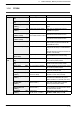
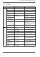


1.1 Table of Relays, Memory Areas and Constants
1-21
1.1.8 Relay Numbers
External input relays (X), External output relays (Y), Internal relays (R), Link relays
(L) and Pulse relays (P)
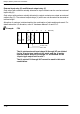
Since these relays are handled in units of 16 points, they are expressed as a
combination of decimal and hexadecimal numbers as shown below.
1,2,3...
Decimal number
0,1,2...9,A,B...F
Hexadecimal number
The maximum value that can be selected varies with each relay.
Example: External input relay (X)
X0, X1 XF..........................
X10, X11 X1F........................
X20, X21 X2F........................
.................................
Timers (T) and Counters (C)
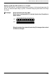
The addresses for timer contacts (T) and counter contacts (C) are correspond to the
timer and counter instruction numbers and expressed in decimals as shown below.
Example: FP2
0, 1, 2 ...
Decimal number
T0, T1 T999..................................
C1000, C1001 C1023.........................
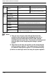
Note
Counters and timers share the same area. The division of the
area can be changed with system register 5. (The table and
example are when settings are the default values.)
Error alarm relays (E) (FP2SH/FP10SH only)
The addresses for error alarm relays (E) are represented in only decimals.
E0, E1 E2047........