
User manual

High−level Instructions
3 − 493
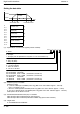
Outline This instruction outputs pulses from the specified channel for the pulse
output according to the specified parameters.
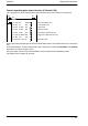
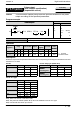
Program example
Ladder
Diagram
Boolean
Ladder Diagram
Address Instruction
10
F171 SPDH , DT100 , K 0
S
n
Trigger
R10
DF
10
11
12
ST R 10
DF
F171 (SPDH)
DT 100
K0
S Starting address of area containing the data table.
n Channel for pulse output.
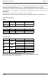
Operands
O
p
erand
Relay Timer/Counter Register
Index
register
Constant
Index
modifier
Operand
WX WY WR SV EV DT I K H
modifier
S N/A N/A N/A N/A N/A A N/A N/A N/A A
n N/A N/A N/A N/A N/A N/A N/A A A N/A
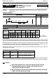
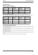
Description
Pulses are output from the specified channel when the corresponding control flag turns off and the execution
condition is in on state.
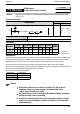
For FPΣ For FP−X Ry type (AFPX−PLS)
Channel no. Output Output method Channel no. Output Output method
ch0 Y0 CW PLS ch0
Casette
Y100 CW PLS
Y1 CCW SIGN
C
asette
mounting part 1
Y101 CCW SIGN
ch2 Y3 CW PLS ch1
Casette
Y200 CW PLS
Y4 CCW SIGN
C
asette
mounting part 2
Y201 CCW SIGN
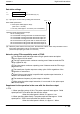
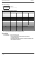
For FP−X Tr type
Channel no. Output Output method
ch0 Y0 CW PLS
Y1 CCW SIGN
ch1 Y2 CW PLS
Y3 CCW SIGN
ch2 Y4 CW PLS
Y5 CCW SIGN
ch3 Y6 CW PLS
Y7 CCW SIGN
Note) There is no ch3 for C14T and C14TD.
Note) The pulse I/O cassette (AFPX−PLS) cannot be installed on the FP−X Tr type.
Note) Use the ch2 and ch3 at up to 20 kHz.
FPΣ/FP−X
Pulse output
(with channel specification)
(trapezoidal control)
5
F171
(SPDH)
Availability
FPΣ/FP−X
A: Available
N/A: Not Available