
User manual

High−level Instructions
3 − 659
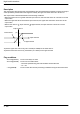
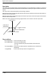
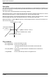
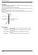
Outline This instruction carries out upper and lower limit control for 32-bit data.
For the FP0R/FPΣ/FP−X, the P type high−level instruction “P286
(PDLIMT)” is not available.
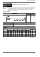
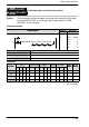
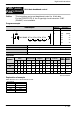
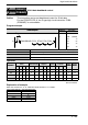
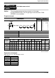
Program example
Ladder
Diagram
Boolean
Ladder Diagram
Address Instruction
S1
Trigger
S3S2 D
F286 DLIMT, DT10, DT20, DT30, DT4010
R0
10
11
ST R 0
F286 (DLIMT)
DT 10
DT 20
DT 30
DT 40
S1 The area where the lower limit is stored or the lower limit data. (2 words)
S2 The area where the upper limit is stored or the upper limit data. (2 words)
S3 The area where the input value is stored or the input value data. (2 words)
D The area where the output value is stored. (2 words)
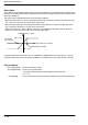
Operands
O
p
erand
Relay Timer/Counter Register
Index
register
Constant
Index
modifier
Integer
device
Operand
WX WY WR WL SV EV DT LD FL I K H f
modifier device
S1 A A A A A A A A A A A A N/A A N/A
S2 A A A A A A A A A A A A N/A A N/A
S3 A A A A A A A A A A A A N/A A N/A
D N/A A A A A A A A A A N/A N/A N/A A N/A
F286
P286
(PDLIMT)
(DLIMT)
32-bit data upper and lower limit control
A
:
A
vailable
N/A: Not Available