www.voicesonic.com Phone 877-289-2829 Installation Manual Pure IP-PBX Model No. KX-NCP500 KX-NCP1000 Panasonic KX-NCP500, KXNCP500, NCP500, KX-NCP1000, KXNCP1000, NCP1000 Thank you for purchasing a Panasonic Pure IP-PBX. Please read this manual carefully before using this product and save this manual for future use. KX-NCP500/KX-NCP1000: PBMPR Software File Version 5.0000 or later SD Logo is a trademark of SD-3C, LLC.
System Components System Components System Components Table Category Main Unit Model No.
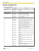
System Components Category Virtual CO Line Cards Model No.
System Components Category Other Physical Cards Cell Stations (CSs) 2.4 GHz DECT 6.0 Proprietary Equipment *1 Model No. Description KX-TDA0161 4-Port Doorphone Card (DPH4) KX-TDA0164 4-Port External Input/Output Card (EIO4) KX-TDA0166 16-Channel Echo Canceller Card (ECHO16) KX-TDA0191 4-Channel Message Card (MSG4) KX-TDA0194 4-Channel Simplified Voice Message Card (ESVM4) KX-T0141 2-Channel Cell Station Unit Using a DHLC/DLC Card (PT-interface CS) for 2.
System Components Note • • *1 For the equipment (e.g., Add-on Key Module, USB Module, Headset*1) that can be connected to a particular telephone, refer to the telephone's manual. For other equipment that can be connected to the PBX, refer to "1.1.2 System Connection Diagram". The KX-T7090 headset can be connected to the KX-T7000, KX-T7200, KX-T7300, and KX-T7400 series telephones. Notice • • • This PBX supports SIP Extensions.
Safety Notices Safety Notices Please observe the safety notices in this manual in order to avoid danger to users or other people, and prevent damage to property. The notices are classified as follows, according to the severity of injury or damage: 6 WARNING This notice means that misuse could result in death or serious injury. CAUTION This notice means that misuse could result in injury or damage to property.
Important Information Important Information SAVE THESE INSTRUCTIONS WARNING SAFETY REQUIREMENTS For All Telephone Equipment • Do not install the product in any other way than described in relevant manuals. • The product must only be installed and serviced by qualified service personnel. The product should be used as-is from the time of purchase; it should not be disassembled or modified. Disassembly or modification can cause a fire, electric shock, or damage to the product.
Important Information e. Do not run any cables under carpeting. • • Unplug this unit from the AC outlet if it emits smoke, an abnormal smell or makes unusual noise. These conditions can cause fire or electric shock. Confirm that smoke has stopped and contact an authorized Panasonic Factory Service Center. Do not insert objects of any kind into this product, as they may touch dangerous voltage points or short out parts that could result in a fire or electric shock.
Important Information Requirements 1. The SD Memory Card contains software for all the processes of the PBX and all customer data. It can be easily removed and taken away from the PBX by a third party. Therefore, do not allow unauthorized access to prevent data leakage. 2. Always make backups of data stored on the SD Memory Card. For details, refer to "2.6.2 Utility—File Transfer PC to PBX (SD Card)" and "2.6.3 Utility—File Transfer PBX (SD Card) to PC" in the PC Programming Manual. 3.
Important Safety Instructions Important Safety Instructions When using your telephone equipment, basic safety precautions should always be followed to reduce the risk of fire, electric shock and injury to persons, including the following: • Do not use the product near water, for example, near a bathtub, wash bowl, kitchen sink, or laundry tub, in a wet basement, or near a swimming pool. • Avoid using wired telephones during an electrical storm. There is a remote risk of electric shock from lightning.
Precaution Precaution WARNING DO NOT REMOVE SD MEMORY CARD WHILE POWER IS SUPPLIED TO THE PBX Doing so may cause the PBX to fail to start when you try to restart the system.
Precaution Password Security CAUTION To the Administrator or Installer regarding the system password 1. Please provide all system passwords to the customer. 2. To avoid unauthorized access and possible abuse of the PBX, keep the passwords secret, and inform the customer of the importance of the passwords, and the possible dangers if they become known to others. 3. The PBX has default passwords preset. For security, change these passwords the first time that you program the PBX. 4.
Introduction Introduction This Installation Manual is designed to serve as an overall technical reference for the Panasonic Pure IP-PBX, KX-NCP500/KX-NCP1000. It provides instructions for installing the hardware, and programming the PBX using the Maintenance Console. The Structure of this Manual This manual contains the following sections: Section 1 System Outline Provides general information on the PBX, including the system capacity and specifications.
F.C.C. REQUIREMENTS AND RELEVANT INFORMATION F.C.C. REQUIREMENTS AND RELEVANT INFORMATION 1. Notification to the Telephone Company 2. 3. 4. 5. 6. 7. This equipment complies with Part 68 of the FCC rules and the requirements adopted by the ACTA. On the side of this equipment is a label that contains, among other information, a product identifier in the format US: ACJMF04BKX-NCP500. If requested, this number must be provided to the telephone company.
F.C.C. REQUIREMENTS AND RELEVANT INFORMATION interference in a residential installation. This equipment generates, uses, and can radiate radio frequency energy and, if not installed and used in accordance with the instructions, may cause harmful interference to radio communications. However, there is no guarantee that interference will not occur in a particular installation.
Table of Contents Table of Contents 1 System Outline .......................................................................................19 1.1 1.1.1 1.1.2 1.2 1.2.1 1.3 1.3.1 1.3.2 1.3.3 Basic System Construction ...........................................................................................20 Main Unit ........................................................................................................................20 System Connection Diagram ........................................
Table of Contents 3.7.5 3.7.6 3.8 3.8.1 3.8.2 3.8.3 3.8.4 3.9 3.9.1 3.10 3.10.1 3.11 3.11.1 3.12 3.12.1 3.13 3.13.1 MSG4 Card (KX-TDA0191) ............................................................................................86 ESVM4 Card (KX-TDA0194) ..........................................................................................87 Connection of Extensions ..............................................................................................
Table of Contents 18 Installation Manual Document Version 2011-10
Section 1 System Outline This section provides general information on the PBX, including the system capacity and specifications.
1.1.1 Main Unit 1.1 Basic System Construction 1.1.1 Main Unit The main unit contains a power supply unit (PSU) and an IPCMPR card for starting and controlling the PBX. KX-NCP500 KX-NCP1000 Construction of the Main Unit A.
1.1.2 System Connection Diagram 1.1.2 System Connection Diagram ITSP*1 Network Private IP Network CO (Telephone Company Lines) Analog/PRI/T1 WAN Remote PC DCE*2 (e.g.
1.1.
1.2.1 Optional Equipment 1.2 Optional Equipment 1.2.1 Optional Equipment Model No. Model Name Description KX-NCP1104 4-Channel VoIP DSP Card (DSP4) 4-channel digital signal processor card with a 4-Channel IP Trunk activation key and an 8-Channel IP Proprietary Telephone activation key preinstalled. Compliant with ITU-T G.729A and G.711 codec methods. To be mounted on the IPCMPR card.
1.2.1 Optional Equipment Model No. Model Name Description KX-TDA0196 Remote Card (RMT) Analog modem card for remote communication with the PBX. ITU-T V.90 support. To be mounted on the IPCMPR card. KX-TDE0110 16-Channel VoIP DSP Card (DSP16) 16-channel digital signal processor card with a 4-Channel IP Trunk activation key and an 8-Channel IP Proprietary Telephone activation key preinstalled. Compliant with ITU-T G.729A and G.711 codec methods. To be mounted on the IPCMPR card.
1.3.1 General Description 1.3 Specifications 1.3.1 General Description Control Bus Original bus (16-bit, 8 MHz, 10 megabytes per second) Communication Bus H.100 bus conformity (1024 time slots) Switching Non-blocking Power Input Power Consumption (when fully mounted) KX-NCP500 100 V AC to 130 V AC; 1.0 A/200 V AC to 240 V AC; 0.6 A; 50 Hz/60 Hz KX-NCP1000 100 V AC to 130 V AC; 1.3 A/200 V AC to 240 V AC; 0.
1.3.
1.3.2 Characteristics 1.3.2 Characteristics Terminal Equipment Loop Limit • • • • PT: KX-DT300/KX-T7600 series DPT: 90 W; all other DPTs/APTs: 40 W SLT: 600 W including set Doorphone: 20 W CS: 65 W Minimum Leakage Resistance 15 000 W minimum Maximum Number of Extension Instruments per Line 1. for PT or SLT 2. by Parallel or eXtra Device Port connection of an APT/DPT and an SLT 3.
1.3.3 System Capacity 1.3.3 System Capacity Type and Maximum Number of Slots The PBX supports the following type and number of slots. Maximum Number Slot Type KX-NCP500 KX-NCP1000 IPCMPR Card Slot 1 1 Regular Free Slot 2 3 Small Free Slot 3 4 Virtual CO Line Slot 4 4 Virtual Extension Slot 4 4 Virtual Slot IPCMPR Card Slot and Free Slots KX-NCP500 A KX-NCP1000 B C A B C A. Small Free Slots B. Regular Free Slots C.
1.3.
1.3.3 System Capacity Maximum Optional Service Cards The following number of cards can be installed in the Free Slots or Virtual Slots of the PBX. Note • • Any card that exceeds the capacity of the PBX will be ignored. When the PBX starts up with an invalid configuration, some cards will be ignored.
1.3.3 System Capacity Cards Mounted on Other Optional Service Cards Maximum Number Card Type Mounted on KX-NCP500 KX-NCP1000 1 1 RMT 1 1 DPH4 4 4 ECHO16 2*1 2*1 4 4 4 4 DSP4 DSP16 DSP64 MSG4 ESVM4 EIO4 *1 IPCMPR Card OPB3 Card Only 1 ECHO16 card can be mounted on each OPB3 card. Maximum CO Lines and Extensions The PBX supports the following number of CO lines and extensions.
1.3.3 System Capacity DSP Card Resources The maximum number of simultaneous calls using IP protocols is determined by the type of call, codec(s) used, and digital signal processor (DSP) card installed in the PBX. Below are some example configurations and the maximum number of simultaneous calls for each. For Calls between Virtual CO Lines and Virtual Extensions Maximum Number of Simultaneous Calls Codec(s) Used *1 DSP4 Card DSP16 Card DSP64 Card G.711 8 32 64 G.711+G.729A*1 2 12 42 G.
1.3.3 System Capacity Maximum Terminal Equipment The following shows the number of each terminal equipment type supported by the PBX.
1.3.3 System Capacity Note for KX-NT265 IP-PT users The supported card varies depending on the software version of your KX-NT265 IP-PT. To confirm the version, follow the procedure below: While starting up SP-PHONE PROGRAM SP-PHONE "AP Version". Select "Maintenance". Select "Version display". To exit the programming mode SP-PHONE HOLD Software version is displayed.
1.3.3 System Capacity Load Figure Calculation Equipment Type PT Extension Card*1 *1 Load Figure KX-DT300 series DPT/KX-DT300 series DSS console/KX-T7600 series DPT/KX-T7600 series DSS console 1 Other DPT/Other DSS console 4 APT 4 IP-PT 0 SIP Extension 0 DHLC4 4 SLC8 8 SLC16 16 PT-interface CS (2-channel) (1 unit) 4 PT-interface CS (8-channel) (1 unit) 8 IP-CS (8-channel) (1 unit) 0 VPS (1 port) 1 Only the extension cards that can support SLTs count for the load figures.
1.3.3 System Capacity Required Card Lines and Equipment Extension *1 Load Figure Small Free Slot Regular Free Slot Virtual Slot DLC16*1 – SLC16 – KX-DT300 series DPT 24 units 28 SLT 16 units 16 KX-NT300 series IP-PT 40 units 0 – – V-IPEXT32 ´2 SIP Extension 0 0 – – – VPS 0 0 – – – CS 0 0 – – – DHLC4 *1 At least 4 of the 20 DPT ports of DHLC4 and DLC16 cards must be assigned as Digital XDP ports.
Section 2 Activation Key Installation This section describes information on activation keys, including how to obtain an activation key and install it in the SD Memory Card.
2.1.1 Activation Keys 2.1 Information about the Activation Keys 2.1.1 Activation Keys To use IP CO lines and IP telephones on a private IP network using the IPCMPR card or to upgrade the software for enhanced features, you need the appropriate activation keys. Activation keys are provided via the DSP cards and optional activation key files.
2.1.1 Activation Keys Activation Key Type Description Maximum Number Supported IP CO Lines/IP Telephones/CA Users CA Supervisor 1user Allows the use of CA ACD Monitor for 1 ICD Supervisor. 4 4 users Software Upgrade 01 Upgrades software to use enhanced features. 1 - *1 *2 You need to set the number of the installed activation key to be used for H.323 CO lines through system programming. By default, all the installed activation keys will be used for SIP CO lines.
2.1.1 Activation Keys Activation Keys for IP Telephones Maximum Number/Supported IP Telephones Model No.
2.1.1 Activation Keys Note • • For information about how to obtain the additional activation keys, refer to "2.1.2 Activation Key Code and Key Management System". For information about how to install the activation key files on the SD Memory Card, refer to "2.1.3 Activation Key File".
2.1.1 Activation Keys Activation Key Installation Example The following shows an example of when using 16 H.323 CO lines, 16 SIP CO lines, 32 IP-PTs, 16 IP softphones, and 16 SIP Extensions on a private IP network using the IPCMPR card. Example: KX-NCP1000 Virtual Extension Slots SD Memory Card 4-Channel IP Trunk 4-Channel IP Trunk 16 IP CO lines (H.
2.1.2 Activation Key Code and Key Management System 2.1.2 Activation Key Code and Key Management System To obtain additional activation keys, you need to purchase the appropriate activation key codes and access the Key Management System. You can download the activation keys as an activation key file from the Key Management System. To download the activation keys, enter the MPR ID number shown on the IPCMPR card in the PBX, and activation key number and registration ID provided on each activation key code.
2.1.3 Activation Key File 2.1.3 Activation Key File The corresponding number of IP CO lines and IP telephones or enhanced features can be activated by installing the downloaded activation key file(s) in the SD Memory Card of the IPCMPR card using the Maintenance Console. Installing the Activation Key File in the SD Memory Card Make sure to install the Maintenance Console on the PC in advance, and connect the PC to the PBX.
Section 3 Installation This section describes the procedures to install the PBX. Detailed instructions for planning the installation site, installing the main unit and optional service cards, and cabling of peripheral equipment are provided. Further information on peripheral equipment installation is included.
3.1.1 Before Installation 3.1 Before Installation 3.1.1 Before Installation Please read the following notes concerning installation and connection before installing the PBX and terminal equipment. Be sure to comply with all applicable laws, regulations, and guidelines.
3.1.1 Before Installation • Do not stack up the optional service cards. Wiring Precautions Be sure to follow these instructions when wiring the unit: CAUTION • • • Avoid using the same AC outlet for computers, telexes, and other office equipment, as noise generated by such equipment may hamper system performance or interrupt the system. Unplug the system from its power source when wiring, and plug the system back in only after all wiring is completed. CO lines should be installed with surge protectors.
3.2.1 Unpacking 3.2 Installation of the PBX 3.2.
3.2.2 Names and Locations 3.2.2 Names and Locations KX-NCP500 Front Back A B D C E FG H I J K L J K L KX-NCP1000 Front Back A B D A. B. C. D. E. F. G. H. I. J. K. L. C E FG H I Small Free Slots RUN Indicator Regular Free Slots ALARM Indicator IPCMPR Card Slot MNT Port LAN Port Hook Clip Power Switch AC Inlet Ground Terminal RS-232C Port Note A Power Supply Unit (PSU) is pre-installed.
3.2.3 Frame Ground Connection 3.2.3 Frame Ground Connection 1. 2. 3. 4. Loosen the screw. Insert a grounding wire (user-supplied). Tighten the screw. Connect the grounding wire to ground. Screw Grounding wire To ground WARNING • • Proper grounding (connection to ground) is very important to reduce the risk to the user of electrocution or to protect the PBX from the bad effects of external noise in the case of a lightning strike.
3.2.4 Installing/Removing the Optional Service Cards 3.2.4 Installing/Removing the Optional Service Cards CAUTION • To protect the back board from static electricity, do not touch parts on the back board in the main unit and on the optional service cards. To discharge static electricity, touch ground or wear a grounding strap. • When the • power switch off before installing or removing the card. When installing or removing the IPCMPR card, the DC power supply must be turned off.
3.2.4 Installing/Removing the Optional Service Cards 3. Turn the 2 screws clockwise to fix the card in place. Screws 4. To remove the card, reverse the procedure above. Note Make sure the screws are tightened to ground the card securely.
3.2.5 Types of Connectors 3.2.
3.2.6 Attaching a Ferrite Core 3.2.6 Attaching a Ferrite Core A ferrite core must be attached when an RJ45 connector is connected to an IPCMPR card. Wrap the cable once around the ferrite core, then close the case of the ferrite core. Attach the ferrite core 3 cm (1-3/16 in) away from the connector. The ferrite core is included with the PBX.
3.2.7 19-inch Rack Mounting 3.2.7 19-inch Rack Mounting WARNING • Be careful not to drop any components. Dropping components may damage them or cause an injury. Only use the 19-inch rack mounting equipment (attachment bracket, screws) included with the PBX. • CAUTION • When the PBX is mounted on a 19-inch rack, make sure that the installation of the unit does not cause the temperature of the rack to exceed its limit.
3.2.8 Floor Standing 3.2.8 Floor Standing When installing the PBX on the floor, make sure to follow these instructions. WARNING Be careful not to drop any components. Dropping components may damage them or cause an injury. CAUTION • • • • Make sure that the PBX is placed as indicated in the diagram below. Do not place it on its side or upside down. Do not block the openings of the PBX. Allow space of at least 20 cm (8 in) above and 10 cm (4 in) at the sides of the PBX.
3.2.9 Surge Protector Installation 3.2.9 Surge Protector Installation CAUTION Performing surge protection is essential. Make sure to follow the instructions in this section. Overview A massive electrical surge can be caused if lightning strikes a telephone cable 10 m (33 ft) above ground, or if a telephone line comes into contact with a power line.
3.2.9 Surge Protector Installation Outside Installation (Main Building) Surge Protector CO Line (Another Building) CO Line Extn. Terminal Board PBX Extn. Surge Protector CS Extn. Extn. SLT PT PT-interface CS SLT PT PT-interface CS CS Ground Extn.: Extension Line If you install an extension outside of the building, the following precautions are recommended: a. Install the extension wire underground. b. Use a conduit to protect the wire.
3.2.9 Surge Protector Installation 1. Connect the ground rod to the surge protector using a grounding wire with a cross-sectional area of at least 1.3 mm2. 2. Bury the ground rod near the protector. The grounding wire should be as short as possible. 3. The grounding wire should run straight to the ground rod. Do not run the wire around other objects. 4. Bury the ground rod at least 50 cm (20 in) underground. Note • • The above figures are recommendations only.
3.3.1 IPCMPR Card 3.3 Information about the Main Processing Card 3.3.1 IPCMPR Card Function The IPCMPR card is the preinstalled main processing card with built-in ESVM card feature (2-channel). The Virtual Cards (CO line/extension) can be installed in Virtual Slots of the IPCMPR card and can be activated with the activation keys. Also, the IPCMPR supports LAN connection so that IP telephones (IP-PTs, IP softphones, SIP Extensions) and PCs can be connected on a private IP network.
3.3.1 IPCMPR Card • • • • • For details about connecting to a LAN, refer to "3.11 LAN Connection" For details about connecting peripherals, refer to "3.10.1 Connection of Peripherals" For details about System Initialize Switch, refer to "3.13.1 Starting the PBX". For details about Reset Button, refer to "5.1.4 Using the Reset Button". Portions of this product contains software of Datalight, Inc. Copyright 1993–2000 Datalight,Inc., All Rights Reserved. WARNING A lithium battery is used in the IPCMPR card.
3.3.
3.3.2 DSP4 Card (KX-NCP1104), DSP16 Card (KX-TDE0110), and DSP64 Card (KX-TDE0111) 3.3.2 DSP4 Card (KX-NCP1104), DSP16 Card (KX-TDE0110), and DSP64 Card (KX-TDE0111) Function DSP4: 4-channel digital signal processor card with a 4-Channel IP Trunk activation key and a 8-Channel IP Proprietary Telephone activation key preinstalled. Compliant with ITU-T G. 729A and G.711 codec methods. To be mounted on the IPCMPR card.
3.3.2 DSP4 Card (KX-NCP1104), DSP16 Card (KX-TDE0110), and DSP64 Card (KX-TDE0111) • 64 When installing the DSP card, hold down the shaded areas of the card to connect it firmly.
3.3.3 RMT Card (KX-TDA0196) 3.3.3 RMT Card (KX-TDA0196) Function Analog modem card for remote communication with the PBX. ITU-T V.90 support. To be mounted on the IPCMPR card.
3.4.1 Virtual Cards 3.4 Information about the Virtual Cards 3.4.1 Virtual Cards Function Virtual Cards are included with the IPCMPR card and can be activated with the appropriate activation key (Only V-IPCS4 cards can be activated without activation keys). By installing Virtual Cards in the Virtual Slots of the IPCMPR card using the Maintenance Console, IP CO lines, IP extensions, and IP-CSs can be used via the IPCMPR card.
3.5.1 LCOT4 Card (KX-NCP1180) 3.5 Information about the Physical CO Line Cards 3.5.1 LCOT4 Card (KX-NCP1180) Function 4-port analog CO line card with Caller ID (FSK/DTMF) and 1 power failure transfer (PFT) port. RJ45 LED To CO line Accessories and User-supplied Items Accessories (included): none User-supplied (not included): RJ45 connector CAUTION To reduce the risk of fire, use only No.26 AWG or larger (e.g., 24 AWG) UL Listed or CSA Certified Telecommunication Line Cord.
3.5.
3.5.2 T1 Card (KX-NCP1187) 3.5.2 T1 Card (KX-NCP1187) Function 1-port T1 CO line card. EIA/TIA standard compliant. LEDs RJ45 A B To NT1 Accessories and User-supplied Items Accessories (included): none User-supplied (not included): RJ45 connector CAUTION • • Connect this optional service card to the CO line through NT1; do not connect to the CO line directly. T1 ports are SELV ports and should only be connected to SELV services.
3.5.2 T1 Card (KX-NCP1187) Pin Assignments RJ45 Connector 1 8 No.
3.5.3 PRI23 Card (KX-NCP1290) 3.5.3 PRI23 Card (KX-NCP1290) Function 1-port ISDN Primary Rate Interface card (23B channels). NI (North American standard ISDN protocol) compliant. RJ45 B A To NT1/ Extension LEDs Accessories and User-supplied Items Accessories (included): none User-supplied (not included): RJ45 connector CAUTION • • Connecting this optional service card to the CO line through an NT1; do not connect to the U interface of the CO line directly.
3.5.3 PRI23 Card (KX-NCP1290) Pin Assignments RJ45 Connector 1 8 No.
3.6.1 DHLC4 Card (KX-NCP1170) 3.6 Information about the Physical Extension Cards 3.6.1 DHLC4 Card (KX-NCP1170) Function 4-port digital hybrid extension card for DPTs, APTs, SLTs, DSS consoles, and PT-interface CSs, with Caller ID (FSK) and 1 power failure transfer (PFT) port. RJ45 LED To extensions Accessories and User-supplied Items Accessories (included): none User-supplied (not included): RJ45 connector Note For details about power failure transfer, refer to "3.12.1 Power Failure Connections".
3.6.
3.6.2 DLC8 Card (KX-NCP1171) 3.6.2 DLC8 Card (KX-NCP1171) Function 8-port digital extension card for DPTs, DSS consoles, and PT-interface CSs. LED RJ45 To extensions Accessories and User-supplied Items Accessories (included): none User-supplied (not included): RJ45 connector Pin Assignments RJ45 Connector D1 D2 1 No.
3.6.3 DLC16 Card (KX-NCP1172) 3.6.3 DLC16 Card (KX-NCP1172) Function 16-port digital extension card for DPTs, DSS consoles, and PT-interface CSs. LED RJ45 To extensions Accessories and User-supplied Items Accessories (included): none User-supplied (not included): RJ45 connector Pin Assignments RJ45 Connector D1 D2 1 No.
3.6.4 SLC8 Card (KX-NCP1173) 3.6.4 SLC8 Card (KX-NCP1173) Function 8-port extension card for SLTs with Caller ID (FSK). LED RJ45 To extensions Accessories and User-supplied Items Accessories (included): none User-supplied (not included): RJ45 connector Pin Assignments RJ45 Connector TR 1 8 No.
3.6.5 SLC16 Card (KX-NCP1174) 3.6.5 SLC16 Card (KX-NCP1174) Function 16-port extension card for SLTs with Caller ID (FSK). LED RJ45 To extensions Accessories and User-supplied Items Accessories (included): none User-supplied (not included): RJ45 connector Pin Assignments RJ45 Connector TR 1 8 No.
3.7.1 OPB3 Card (KX-NCP1190) 3.7 Information about the Other Physical Cards 3.7.1 OPB3 Card (KX-NCP1190) Function Optional 3-slot base card for mounting a maximum of 3 option cards from the following: • DPH4 card • EIO4 card • ECHO16 card • MSG4 card • ESVM4 card LED Accessories and User-supplied Items Accessories (included): none User-supplied (not included): none WARNING A lithium battery is used in the OPB3 card. There is a risk of explosion if the battery is replaced with the incorrect type.
3.7.2 DPH4 Card (KX-TDA0161) 3.7.2 DPH4 Card (KX-TDA0161) Function 4-port doorphone card for 4 doorphones and 4 door openers. To be mounted on the OPB3 card. Fully insert the connectors through the panel openings.
3.7.2 DPH4 Card (KX-TDA0161) Pin Assignments 8-pin Terminal Block 8 1 No. Signal Name Function 1 DP4 Doorphone 4 transmit 2 com4 Doorphone 4 receive 3 DP3 Doorphone 3 transmit 4 com3 Doorphone 3 receive 5 DP2 Doorphone 2 transmit 6 com2 Doorphone 2 receive 7 DP1 Doorphone 1 transmit 8 com1 Doorphone 1 receive No.
3.7.3 EIO4 Card (KX-TDA0164) 3.7.3 EIO4 Card (KX-TDA0164) Function 4-port external input/output card. To be mounted on the OPB3 card. Fully insert the connectors through the panel openings.
3.7.3 EIO4 Card (KX-TDA0164) Pin Assignments 8-pin Terminal Block 8 1 No. Signal Name Function 1 C4b Control 4 2 C4a Control 4 com 3 C3b Control 3 4 C3a Control 3 com 5 C2b Control 2 6 C2a Control 2 com 7 C1b Control 1 8 C1a Control 1 com No.
3.7.3 EIO4 Card (KX-TDA0164) External Sensor Power to the external sensor is provided from the EIO4 card and must be grounded through the EIO4 card as indicated in the diagram below. A pair of "sensor" and "common" lines are connected to the EIO4 card for each external sensor. The PBX detects input from the sensor when the signal is under 100 W. Connection Diagram PBX OPB3 EIO4 +5V 33 10K I/O 4.7K External Sensor +5V sensor 33 common 4.
3.7.4 ECHO16 Card (KX-TDA0166) 3.7.4 ECHO16 Card (KX-TDA0166) Function 16-channel card for echo cancellation during conferences. To be mounted on the OPB3 card. Screws inside ECHO16 Card OPB3 Card Accessories and User-supplied Items Accessories (included): Screws ´ 3 User-supplied (not included): none Note To establish a conference call involving 6 to 8 parties, install an ECHO16 card and enable echo cancellation for conferences using the Maintenance Console.
3.7.5 MSG4 Card (KX-TDA0191) 3.7.5 MSG4 Card (KX-TDA0191) Function 4-channel message card. To be mounted on the OPB3 card.
3.7.6 ESVM4 Card (KX-TDA0194) 3.7.6 ESVM4 Card (KX-TDA0194) Function 4-channel simplified voice message card for Simplified Voice Message feature. Also supports MSG card features. To be mounted on the OPB3 card. Screws inside ESVM4 Card OPB3 Card Accessories and User-supplied Items Accessories (included): Screws ´ 3 User-supplied (not included): none CAUTION When installing/uninstalling an ESVM card, be careful not to damage the chips around the connection parts.
3.8.1 Maximum Cabling Distances of the Extension Wiring (Twisted Cable) 3.8 Connection of Extensions 3.8.
3.8.1 Maximum Cabling Distances of the Extension Wiring (Twisted Cable) DLC16, DLC8 Cards PT-interface CS DPT ü ü APT DSS Console SLT ü "ü" indicates that the extension card supports the terminal.
3.8.2 Parallel Connection of the Extensions 3.8.2 Parallel Connection of the Extensions Any SLT can be connected in parallel with an APT or a DPT as follows. Note In addition to an SLT, an answering machine, a fax machine or a modem (PC) can be connected in parallel with an APT or a DPT. With APT For parallel connection, eXtra Device Port (XDP) mode must be disabled for that port through system programming. Refer to "13.1.2 Paralleled Telephone" and "5.1.
3.8.2 Parallel Connection of the Extensions With DPT Parallel mode or eXtra Device Port (XDP) mode can be selected through system programming. If XDP mode is enabled through system programming, parallel connection is not possible. Refer to "13.1.2 Paralleled Telephone" and "5.1.7 Extension Port Configuration" in the Feature Manual for further information. Using a Modular T-Adaptor To DHLC4 card Modular T-Adaptor 2-conductor wiring cord Connect pins "T" and "R".
3.8.2 Parallel Connection of the Extensions With KX-T7600 Series DPT (except KX-T7665) To DHLC4 card 2-conductor wiring cord Connect pins "T" and "R". 4-conductor wiring cord Connect pins "T", "R", "D1" and "D2". DPT SLT TO MAIN UNIT TO TEL / PABX To DHLC4 card To SLT With Other DPT To DHLC4 card 2-conductor wiring cord Connect pins "T" and "R". 4-conductor wiring cord Connect pins "T", "R", "D1" and "D2".
3.8.3 Digital EXtra Device Port (Digital XDP) Connection 3.8.3 Digital EXtra Device Port (Digital XDP) Connection A DPT can be connected to another DPT on the Digital XDP connection. In addition, if the DPT is connected to a DHLC4 card, it can also have an SLT connected in Parallel mode or XDP mode. Note • • • • Both DPTs must be KX-DT300/KX-T7600 series DPTs (except KX-T7640). Note that the KX-T7667 can only be connected as a slave DPT.
3.8.3 Digital EXtra Device Port (Digital XDP) Connection Using an EXtra Device Port To DLC8/DLC16 card To DHLC4 card (for connection of SLT) 4-conductor wiring cord Connect pins "T", "R", "D1" and "D2". 4-conductor wiring cord Connect pins "T", "R", 2-conductor wiring cord "D1" and "D2". Connect pins "T" and "R".
3.8.3 Digital EXtra Device Port (Digital XDP) Connection With KX-T7600 Series DPT Using a Modular T-Adaptor To DLC8/DLC16 card Modular T-Adaptor To DHLC4 card (for connection of SLT) 2-conductor wiring cord Connect pins "T" and "R". 4-conductor wiring cord Connect pins "D1" and "D2". 4-conductor wiring cord Connect pins "D1" and "D2".
3.8.3 Digital EXtra Device Port (Digital XDP) Connection Using an EXtra Device Port To DLC8/DLC16 card To DHLC4 card (for connection of SLT) 4-conductor wiring cord Connect pins "T", "R", "D1" and "D2". 4-conductor wiring cord Connect pins "T", "R", 2-conductor wiring cord "D1" and "D2". Connect pins "T" and "R".
3.8.4 First Party Call Control CTI Connection 3.8.4 First Party Call Control CTI Connection CTI connection between a PC and a KX-DT343/KX-DT346/KX-T7633/KX-T7636 DPT provides first party call control. The CTI connection is made via a USB interface (version 2.0), and uses the TAPI 2.1 protocol. A USB Module must be connected to the DPTs. Note The operating system of the PC required for first party call control depends on your CTI application software.
3.9.1 Connection of Doorphones, Door Openers, External Sensors, and External Relays 3.9 Connection of Doorphones, Door Openers, External Sensors, and External Relays 3.9.1 Connection of Doorphones, Door Openers, External Sensors, and External Relays The PBX supports a maximum of 16 doorphones, 16 door openers, 16 external sensors, and 16 external relays. Note Doorphones, door openers, external sensors, and external relays are user-supplied.
3.9.1 Connection of Doorphones, Door Openers, External Sensors, and External Relays Note for KX-T7765 Users When loosening/tightening the screw, do not scratch the cabinet wall with the driver shaft. Cabinet Wall 2. Pass the wires through the hole in the base cover, and attach the base cover to a wall using 2 screws. Screw To 8-pin terminal block Note Two kinds of screws are included with the doorphone. Please choose the appropriate kind for your wall type.
3.9.1 Connection of Doorphones, Door Openers, External Sensors, and External Relays Connection Use 8-pin and 10-pin terminal blocks (included with the card) for connection. 1. While pressing down on the hole at the top of the terminal block using a screwdriver, insert the wire into the side hole as shown below. Repeat this procedure for other doorphones, door openers, external sensors, and external relays. Refer to "3.7.2 DPH4 Card (KX-TDA0161)" and "3.7.3 EIO4 Card (KX-TDA0164)" for pin assignments.
3.10.1 Connection of Peripherals 3.10 Connection of Peripherals 3.10.
3.10.1 Connection of Peripherals BGM/MOH The PBX provides Background Music and Music on Hold. An external music source (e.g., user-supplied radio) can be connected to the PBX. CAUTION The External Music Jack is an SELV port and should only be connected to an approved SELV device. Notice • Wiring should be done carefully to prevent undue force being exerted on the plug. Otherwise, sound may only be heard intermittently.
3.10.1 Connection of Peripherals Connection Charts For connecting a printer/PC with a 9-pin RS-232C connector Printer/PC (9-pin) PBX (9-pin) Circuit Type (EIA) Signal Name Pin No. Pin No.
3.10.1 Connection of Peripherals • • 104 Clear To Send (CTS):…(input) An ON condition of circuit CS (CTS) indicates that the printer or the PC is ready to receive data from the unit. The unit does not attempt to transfer data or receive data when circuit CS (CTS) is OFF. Frame Ground (FG) Connects to the unit frame and the ground conductor of the AC power cord.
3.11.1 LAN Connection 3.11 LAN Connection 3.11.1 LAN Connection Connection Chart for LAN Connection The PBX is equipped with a LAN port for connecting to a LAN so that IP telephones (IP-PTs, IP softphones, SIP Extensions), IP-CSs, PCs and a CTI Server can be connected on a private IP network. IP Softphone, CA Client PC PC Switching Hub LAN Port CTI Server IP-PT IP-CS SIP Extension Switching Hub PBX (LAN Port) Signal Name Pin No. Pin No.
3.12.1 Power Failure Connections 3.12 Power Failure Connections 3.12.1 Power Failure Connections When the power supply to the PBX fails, power failure transfer (PFT) will switch from the current connection to the Power Failure Connection. Refer to "13.1.11 Power Failure Transfer" in the Feature Manual for further information. Using Analog CO Line Card and Extension Card Power Failure Connection connects a specific SLT and a CO line in the event of power failure.
3.12.1 Power Failure Connections RJ45 Connector Pin Assignments for Analog CO line Card PFT Port RT 1 8 No. Signal Name Function 1-3 Reserved – 4 R Ring 5 T Tip 6-8 Reserved – RJ45 Connector Pin Assignments for Extension Card PFT Port TR 1 8 Document Version 2011-10 No.
3.13.1 Starting the PBX 3.13 Starting the PBX 3.13.1 Starting the PBX WARNING Make sure that the AC outlet is properly grounded, then securely connect the 3-pin AC plug including the grounded pin. CAUTION • • • • Use only the AC power cord included with the PBX. Before touching the System Initialize Switch, discharge static electricity by touching ground or wearing a grounding strap. Once you have started the PBX and if you unplug the PBX, do not perform the following procedures to start the PBX again.
3.13.1 Starting the PBX 2. Plug the AC power cord into the PBX and pass the cord through the hook clip as indicated. Push the hook clip in the direction of the arrow until it clicks. Note For safety reasons, do not stretch or pinch the AC power cord. To grounded AC Outlet 3. Plug the other end of the cord into an AC outlet and turn on the PBX. The RUN indicator will flash. 4. While the RUN indicator is flashing, slide the System Initialize Switch back to the "NORMAL" position.
3.13.1 Starting the PBX Confirming the CO Line Connection After initialization, program the PBX and connect CO lines to the PBX. To confirm that the CO lines are successfully connected, dial [ ] [3] [7] + CO line number (3 digits) on a PT, or press the PT's S-CO button. You will hear a dial tone if the CO line is available and connected.
Section 4 Guide for the Maintenance Console Explains the installation procedure, structure, and basic information of the Maintenance Console.
4.1.1 Overview 4.1 Overview 4.1.1 Overview The Maintenance Console is designed to serve as an overall system programming reference for the PBX. To program and administer the PBX by PC, you need to install the Maintenance Console onto the PC. This section describes overview and installation of the Maintenance Console only. Menu Bar System Menu Note The contents and design of the software are subject to change without notice.
4.2.1 PC Connection 4.2 PC Connection 4.2.1 PC Connection Connection via MNT Port of IPCMPR Card MNT Port To LAN Port Notice When connecting a PC to the PBX, a fixed IP address must be assigned to the PC. For information about fixed IP addresses, ask your network administrator. Note For pin assignments and maximum cabling distance, refer to "3.10.1 Connection of Peripherals". Serial Interface Connection To COM Port PC RS-232C Port CAUTION To protect the system, keep the following in mind: 1.
4.2.1 PC Connection External Modem Connection Modem To RS-232C port (25-pin) To CO line/PBX extension port assigned as the CO line destination RS-232C Port (9-pin) External Modem (25-pin) PBX (9-pin) Signal Name Pin No. Pin No. Signal Name RD (RXD) 3 2 RD (RXD) SD (TXD) 2 3 SD (TXD) ER (DTR) 20 4 ER (DTR) DR (DSR) 6 6 DR (DSR) CAUTION To protect the system, keep the following in mind: 1.
4.3.1 Installing and Starting the Maintenance Console 4.3 Installation of the Maintenance Console 4.3.1 Installing and Starting the Maintenance Console System Requirements Required Operating System • Microsoft® Windows® XP, Windows Vista® Business, or Windows 7 Professional operating system Minimum Hardware Requirements • HDD: 100 MB of available hard disk space • The PC must fulfill the hardware requirements of the installed Microsoft Windows operating system.
4.3.1 Installing and Starting the Maintenance Console 5. Click Connect. 6. a. Select KX-NCP500/1000 from PBX Model. b. Select the LAN or RS-232C tab, depending on the type of PC connection with the PBX. c. Specify the settings as required. Note When connecting to the PBX for the first time selecting LAN, the IP Address and Port Number must be set to 192.168.0.101 and 35300 respectively. d. Enter the system password for installer (default: 1234). e. Click Connect. 7.
4.3.1 Installing and Starting the Maintenance Console Characters which can be displayed on a KX-DT300/KX-T7600 series PT are shown below in the white cells. • The PC will not perform any shutdown operation, or enter the power-saving system standby mode while the Maintenance Console is connected to the PBX. To perform either of the operations above, first close the connection to the PBX.
4.3.
Section 5 Troubleshooting This section provides information on the PBX and telephone troubleshooting.
5.1.1 Installation 5.1 Troubleshooting 5.1.1 Installation PROBLEM You cannot make/receive calls via an IP network. PROBABLE CAUSE SOLUTION • DSP card malfunction • Replace the corresponding card. • IPCMPR card malfunction • Replace the IPCMPR card (be sure to turn off the PBX when replacing). • Not enough activation keys • Purchase additional activation key codes. Please consult a certified dealer for details.
5.1.1 Installation PROBLEM Extensions (except IP-PT/ SIP Extension) do not operate. PROBABLE CAUSE SOLUTION • Extension card malfunction • Replace the corresponding card. • Poor connection between the PBX and the extension • Take the extension and plug it into the same extension port using a short telephone cord. If the extension works, then the connection between the PBX and the extension must be repaired. • A telephone with an A-A1 relay is connected.
5.1.1 Installation PROBLEM The LINK indicator of the IPCMPR does not turn on. PROBABLE CAUSE SOLUTION • IPCMPR card malfunction • Replace the IPCMPR card (be sure to turn off the PBX when replacing). • Poor connection. • Make sure that an 8-pin twisted pair cable is used for connection. Make sure that none of the CAT 5 cables in use are over 100 m (328 ft) in length. Make sure that a straight cable is used for connection to a switching hub.
5.1.2 Connection 5.1.2 Connection Connection between the PBX and a PT: Can you dial an extension? CAUSE No SOLUTION The T/R is connected to the D1/D2. D1 T R D2 D1 T R D2 PBX Use the correct cord (the inner 2 wires are for T/R and the outer 2 wires are for D1/D2) Extension Connection between the PBX and an SLT: CAUSE SOLUTION The T/R is connected to the D1/D2. D1 T R D2 PBX Yes T R Extension Use the correct cord (the inner 2 wires are for T/R).
5.1.2 Connection Connection between the central office and the PBX: (Continued from the previous page.) Can you dial out on a CO line? CAUSE CO line is connected to the T2/T1. T2 R1 T1 R2 No CO line SOLUTION Reconnect the CO line to the T1/R1 or T2/R2 of the telephone jack using 2conductor wiring. PBX CO line is connected to the T2/R1.
5.1.3 Operation 5.1.3 Operation PROBLEM PROBABLE CAUSE SOLUTION • Cannot set the IP address, subnet mask address, and PBX IP address to the IP-PT. • An unusable value is being set. • Set an IP address within the valid range. IP address of the IP-PT/PBX: "1.0.0.0" to "223.255.255.255" Subnet mask address: "0–255.0–255.0–255.0–255" (except 0.0.0.0 and 255.255.255.255) • Cannot register the IP-PT. • The necessary network parameters are not set to the IP-PT.
5.1.3 Operation PROBLEM 126 PROBABLE CAUSE SOLUTION • Originating an outside call, call transfer, or conference cannot be performed. • The corresponding flexible button does not exist on the PT. • Program the flexible button. Refer to "6.1.3 Flexible Buttons" in the Feature Manual. • The KX-HGT100 does not work properly, or some features cannot be performed using KX-HGT100. • The firmware of the KX-HGT100 and the MPR software file version of the PBX are not upgraded to their latest versions.
5.1.4 Using the Reset Button 5.1.4 Using the Reset Button If the PBX does not operate properly, use the Reset Button. Before using the Reset Button, try the system feature again to confirm whether there definitely is a problem or not. CAUTION In order to avoid possible corruption of data on the SD Memory Card, please ensure that the "SD ACCESS" LED is off before pressing the Reset Button.
5.1.5 Troubleshooting by Error Log 5.1.5 Troubleshooting by Error Log When a major system error occurs in the PBX, the ALARM indicator on the front of the cabinet turns on red, and the system logs the error information. Error Log Display Format Below is the display format of the error log. For information about how to view the error log using the Maintenance Console, refer to "2.6.8 Utility—Error Log" in the PC Programming Manual.
5.1.5 Troubleshooting by Error Log Item 5 Sub Code Description The 6-digit sub code of the relevant hardware (X1YYZZ).
5.1.
Section 6 Appendix Document Version 2011-10 Installation Manual 131
6.1.1 PBMPR Software File Version 1.01xx 6.1 Revision History 6.1.1 PBMPR Software File Version 1.01xx Changed Contents • 132 4.3.
6.1.2 PBMPR Software File Version 2.02xx 6.1.2 PBMPR Software File Version 2.02xx New Options • System Components Table – KX-NCS2240 Activation Key for CA PRO for 40 Users (CA Pro 40users) – KX-NCS2249 Activation Key for CA PRO for 128 Users (CA Pro 128users) – KX-NCP0158 DECT 6.0 8-Channel IP Cell Station Unit Using a V-IPCS4 Card for DECT 6.0 Portable Station – - Virtual 4 IP Cell Station Interface Card (V-IPCS4) Changed Contents • • • • • • • • 1.1.2 System Connection Diagram 1.3.
6.1.3 PBMPR Software File Version 4.1xxx 6.1.3 PBMPR Software File Version 4.1xxx Changed Contents • • • 134 1.3.3 System Capacity 2.1.1 Activation Keys 2.1.
6.1.4 PBMPR Software File Version 5.0xxx 6.1.4 PBMPR Software File Version 5.0xxx Changed Contents • • • 1.3.3 System Capacity – Maximum Optional Service Cards – Maximum CO Lines and Extensions – Maximum Terminal Equipment – Digital EXtra Device Port (Digital XDP) Connection Capacity – Power Supply Unit Capacity 2.1.1 Activation Keys 3.3.
6.1.4 PBMPR Software File Version 5.
Index Document Version 2011-10 Installation Manual 137
Index Numerics 16-Channel Echo Canceller Card (KX-TDA0166) 23, 85 16-Channel IP Proprietary Telephone Activation Key (KX-NCS3516) 40 16-Channel IP Softphone/IP Proprietary Telephone Activation Key (KX-NCS3216) 40 16-Channel SIP Extension Activation Key (KX-NCS3716) 40 16-Channel VoIP DSP Card (KX-TDE0110) 24, 63 16-Port Digital Extension Card (KX-NCP1172) 23, 76 16-Port Single Line Telephone Extension Card (KX-NCP1174) 23, 78 19-inch Rack Mounting 55 1-Channel IP Proprietary Telephone Activation Key (KX-NC
Index KX-NCP1171 (8-Port Digital Extension Card) 23, 75 KX-NCP1172 (16-Port Digital Extension Card) 23, 76 KX-NCP1173 (8-Port Single Line Telephone Extension Card) 23, 77 KX-NCP1174 (16-Port Single Line Telephone Extension Card) 23, 78 KX-NCP1180 (4-Port Analog Trunk Card) 23, 67 KX-NCP1187 (T-1 Trunk Card) 23, 69 KX-NCP1190 (Optional 3-Slot Base Card) 23, 79 KX-NCP1290 (PRI Card [PRI23]) 23, 71 KX-NCS2201 (Activation Key for CA PRO for 1 User) 40 KX-NCS2205 (Activation Key for CA PRO for 5 Users) 40 KX-NC
Index Slots for Virtual CO Line Cards 28 Slots for Virtual Extension Cards 28 Specifications 25 Specifications, Characteristics 27 Specifications, General Description 25 Specifications, System Capacity 28 Starting the PBX 108 Surge Protector Installation 57 System Capacity 28 System Connection Diagram 21 System Initialization Procedure 108 System Initialize Switch 108, 127 System Requirements 115 T T1 Card (KX-NCP1187) 69 T-1 Trunk Card (KX-NCP1187) 23, 69 Terminal Equipment, Maximum Number 33 Troubleshoo
Notes Document Version 2011-10 Installation Manual 141
When you ship the product Carefully pack and send it prepaid, adequately insured and preferably in the original carton. Attach a postagepaid letter, detailing the symptom, to the outside of the carton. DO NOT send the product to the Executive or Regional Sales offices. They are NOT equipped to make repairs. Product Service Panasonic Factory Service Centers for this product are listed in the service center directory. Consult your certified Panasonic dealer for detailed instructions.