Hybrid IP-PBX Installation Manual Model no. KX-TDA30 Thank you for purchasing the Panasonic Hybrid IP-PBX, KX-TDA30. Please read this manual carefully before using this product and save this manual for future use. SD Logo is a trademark.
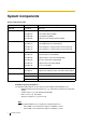
System Components System Components Table Model Description Main Unit KX-TDA30 Main Unit Trunk Cards KX-TDA3180 4-Port Analogue Trunk Card (LCOT4) KX-TDA3193 4-Port Caller ID Card (CID4) KX-TDA3280 2-Port BRI Card (BRI2) KX-TDA3480 4-Channel VoIP Gateway Card (IP-GW4) KX-TDA3171 4-Port Digital Extension Card (DLC4) KX-TDA3172 8-Port Digital Extension Card (DLC8) KX-TDA3173 4-Port Single Line Telephone Extension Card (SLC4) KX-TDA3174 8-Port Single Line Telephone Extension Card (SLC8) K
• • • KX-T123200 series Proprietary Telephones and DSS consoles KX-T7500 Digital Portable Station KX-TD7500 DECT Portable Station For the equipment (e.g., Add-on Key Module, USB Module, Headset*1) that can be connected to a particular telephone, refer to the telephone's manual. For other equipment that can be connected to the Hybrid IP-PBX, refer to "1.2.2 System Connection Diagram".
Important Safety Instructions SAFETY REQUIREMENTS When using your telephone equipment, basic safety precautions should always be followed to reduce the risk of fire, electric shock and injury to persons, including the following: 1. Read and understand all instructions. 2. Follow all warnings and instructions marked on the product. 3. Unplug this product from the wall outlet before cleaning. Do not use liquid cleaners or aerosol cleaners. Use a damp cloth for cleaning. 4.
f) If the product exhibits a distinct change in performance. 14. Avoid using a telephone (other than a cordless type) during an electrical storm. There may be a remote risk of electric shock from lightning. 15. Do not use the telephone to report a gas leak in the vicinity of the leak.
Precaution • • • • • Keep the unit away from heating appliances and electrical noise generating devices such as fluorescent lamps, motors and televisions. These noise sources can interfere with the performance of the Hybrid IP-PBX. This unit should be kept free of dust, moisture, high temperature (more than 40 °C) and vibration, and should not be exposed to direct sunlight. Never attempt to insert wires, pins, etc. into the vents or other holes of this unit.
• • • • • WHEN A FAILURE OCCURS WHICH EXPOSES ANY INTERNAL PARTS, DISCONNECT THE POWER SUPPLY CORD IMMEDIATELY AND RETURN THIS UNIT TO YOUR DEALER. DISCONNECT THE TELECOM CONNECTION BEFORE DISCONNECTING THE POWER CONNECTION PRIOR TO RELOCATING THE EQUIPMENT, AND RECONNECT THE POWER FIRST. THIS UNIT IS EQUIPPED WITH AN EARTHING CONTACT PLUG. FOR SAFETY REASONS THIS PLUG MUST ONLY BE CONNECTED TO AN EARTHING CONTACT SOCKET WHICH HAS BEEN INSTALLED ACCORDING TO REGULATIONS.
The KX-TDA30E, the KX-TDA30NE, the KX-TDA30GR, and the KX-TDA30CE are designed to interwork with the: • Analogue Public Switched Telephone Network (PSTN) of a European country • Pan-European Integrated Services Digital Network (ISDN) using ISDN basic rate access We, Panasonic Communications Co., Ltd./Panasonic Communications Company (U.K.) Ltd., declare that this equipment is in compliance with the essential requirements and other relevant provisions of Directive 1999/5/EC.
Introduction This Installation Manual is designed to serve as an overall technical reference for the Panasonic Hybrid IP-PBX, KX-TDA30. It provides instructions for installing the hardware, and programming the Hybrid IP-PBX using the KX-TDA Maintenance Console. The Structure of this Manual This manual contains the following sections: Section 1 System Outline Provides general information on the Hybrid IP-PBX, including the system capacity and specifications.
Precautions for Users in the United Kingdom FOR YOUR SAFETY, PLEASE READ THE FOLLOWING TEXT CAREFULLY. This appliance is supplied with a moulded three pin mains plug for your safety and convenience. A 5 amp fuse is fitted in this plug. Should the fuse need to be replaced, please ensure that the replacement fuse has a rating of 5 amps and that it is approved by ASTA or BSI to BS1362. Check for the ASTA mark or the BSI mark on the body of the fuse.
How to replace the fuse: Open the fuse compartment with a screwdriver and replace the fuse and fuse cover. This equipment should be used on PSTN lines requiring 2-wire Loop calling unguarded clearing with Loop Disconnect or DTMF address signalling. The equipment must be connected to direct extension lines and a payphone should not be connected as an extension.
Table of Contents 1 System Outline .............................................................................. 15 1.1 1.1.1 1.2 1.2.1 1.2.2 1.3 1.3.1 1.4 1.4.1 1.4.2 1.4.3 2 Installation ..................................................................................... 29 2.1 2.1.1 2.2 2.2.1 2.2.2 2.2.3 2.2.4 2.2.5 2.2.6 2.2.7 2.2.8 2.2.9 2.2.10 2.2.11 2.3 2.3.1 2.3.2 2.3.3 2.3.4 2.4 2.4.1 2.4.2 2.4.3 2.4.4 2.5 2.5.1 2.5.2 2.5.3 2.5.4 2.5.5 2.5.6 2.6 2.6.1 12 System Highlights .................
2.6.2 2.6.3 2.6.4 2.6.5 2.7 2.7.1 2.7.2 2.7.3 2.7.4 2.7.5 2.7.6 2.7.7 2.7.8 2.8 2.8.1 2.8.2 2.8.3 2.8.4 2.8.5 2.8.6 2.8.7 2.8.8 2.9 2.9.1 2.10 2.10.1 2.11 2.11.1 2.12 2.12.1 3 Guide for the KX-TDA Maintenance Console ........................... 143 3.1 3.1.1 3.2 3.2.1 3.3 3.3.1 3.3.2 3.3.3 3.3.4 4 Parallel Connection of the Extensions .....................................................................80 Extra Device Port (XDP) Connection ...............................................................
Installation Manual
Section 1 System Outline This section provides general information on the Hybrid IP-PBX, including the system capacity and specifications.
1.1 System Highlights 1.1 System Highlights 1.1.1 System Highlights Networking Features This Hybrid IP-PBX supports the following networking features: Virtual Private Network (VPN) VPN is a service provided by the telephone company. It uses an existing line as if it were a private line. Voice over Internet Protocol (VoIP) Network The PBX can connect to another PBX via an IP-type private network. In this case, voice signals are converted into IP packets and sent through this network.
1.1 System Highlights PC Phone/PC Console Features This Hybrid IP-PBX supports the connection of a PC Phone and a PC Console. The Hybrid IPPBX provides advanced features by using a PC Phone and a PC Console.
1.2 Basic System Construction 1.2 Basic System Construction 1.2.1 Main Unit The main unit is equipped with 4 hybrid extension ports. For system expansion, optional service cards can be installed, and an additional AC adaptor can also be connected.
1.2 Basic System Construction 1.2.
1.
1.3 Options 1.3 Options 1.3.1 Options Model No. Model Name Description Maximum Quantity KX-TDA3161 4-Port Doorphone Card (DPH4) 4-port doorphone card for 4 doorphones, 4 door openers (relays) and 4 sensors. 1 KX-TDA3162 2-Port Doorphone Card (DPH2) 2-port doorphone card for 2 doorphones, 2 door openers, 4 relays, and 4 sensors. 1 KX-TDA3166 8-Channel Echo 8-channel card for echo cancellation in Canceller Card (ECHO8) the Conference Mode.
1.3 Options Model No. KX-A236 22 Model Name Additional AC Adaptor and AC Cord Installation Manual Description AC adaptor and AC cord for system expansion.
1.4 Specifications 1.4 Specifications 1.4.1 General Description Switching AC Adaptor Non Blocking Distributed Time Switch AC Input 100 V AC to 240 V AC, 1.5 A, 50 Hz/60 Hz DC Output 40 V, 1.38 A (55.
1.4 Specifications Extension Connection Cable SLT 1 pair wire (T, R) DPT 1-pair wire (D1, D2) or 2-pair wire (T, R, D1, D2) APT 2-pair wire (T, R, D1, D2) DSS Console and Add-on Key Module 1-pair wire (D1, D2) Dimension 275 mm (W) × 376 mm (H) × 117 mm (D) Weight (when fully mounted) Under 3.
1.4 Specifications 1.4.
1.4 Specifications 1.4.3 System Capacity Maximum Number of Cards for Each Slot The following number of trunk and extension cards can be installed in the Hybrid IP-PBX for expansion.
1.4 Specifications Terminal Equipment Type With the Supplied AC Adaptor only With the Supplied AC Adaptor and an Additional AC Adaptor SLT+DPT+APT+CS+VM 28*1 28*1 DPT (KX-T7200, KX-T7400)+APT+CS 8*1 24 *1 The maximum number of each terminal equipment is described above.
1.
Section 2 Installation This section describes the procedures to install the Hybrid IP-PBX. Detailed instructions for planning the installation site, installing the shelves and optional service cards, and cabling of peripheral equipment are provided. Further information on system expansion and peripheral equipment installation is included.
2.1 Before Installation 2.1 Before Installation 2.1.1 Before Installation Please read the following notes concerning installation and connection before installing the Hybrid IP-PBX. Be sure to comply with applicable local regulations (e.g., law, guidelines). Safety Installation Instructions When installing telephone wiring, basic safety precautions should always be followed to reduce the risk of fire, electric shock and injury to persons, including the following: 1.
2.1 Before Installation 3. Avoid using the same power supply outlet for computers, telexes, and other office equipment. Otherwise, Hybrid IP-PBX operation may be interrupted by the induction noise from such equipment. 4. Please use 1-pair telephone wire for extension connection of (telephone) equipment such as standard telephones, data terminals, answering machines, computers, Voice Processing Systems, etc., except PTs (e.g., KX-T7600 series). 5.
2.2 Installation of the Hybrid IP-PBX 2.2 Installation of the Hybrid IP-PBX 2.2.
2.2 Installation of the Hybrid IP-PBX 2.2.2 Names and Locations SD Memory Card Slot Reset Button System Clear Switch Pager port MOH port Hybrid Extension Ports Ground Terminal Battery Connector DC IN 2 DC IN 1 RS232C port USB port Power Switch Notes • • • • DC IN 1: Used for an AC adaptor which is supplied with the Hybrid IP-PBX. DC IN 2: Used for an additional AC adaptor. For details about connecting peripherals, refer to "2.10.1 Connection of Peripherals".
2.2 Installation of the Hybrid IP-PBX 2.2.3 Opening/Closing the Covers Opening the Covers 1. Move the slide button to the right, and slide the cable cover upwards. Then remove the cable cover by rotating it in the direction of the arrow. Slide Button 2. Loosen three screws.
2.2 Installation of the Hybrid IP-PBX 3. Open the front cover, holding the protrusions on the both sides of the front cover. 4. Remove the front cover, pushing it in the direction of the arrow.
2.2 Installation of the Hybrid IP-PBX Closing the Covers 1. Fit the front cover to the main unit as shown below, and then close the front cover. 2. Tighten three screws.
2.2 Installation of the Hybrid IP-PBX 3. Fit the protrusions on the cable cover to the receptacles on the main unit. 4. Slide the cable cover in the direction of the arrow until it locks.
2.2 Installation of the Hybrid IP-PBX 2.2.4 Installation of the SD Memory Card SD Memory Card Slot LOCK SD Memory Card CAUTION • • • Use only the SD Memory Card included with the Hybrid IP-PBX. SD Memory Card contains software for all processes of the Hybrid IP-PBX and all customer data. The SD Memory Card must be inserted before start up. Do not remove the SD Memory Card during the operation of the Hybrid IP-PBX.
2.2 Installation of the Hybrid IP-PBX 2.2.5 Frame Earth Connection IMPORTANT Connect the frame of the Hybrid IP-PBX to earth. 1. Loosen the screw. 2. Insert an earthing wire (usersupplied)*. 3. Tighten the screw. 4. Connect the earthing wire to earth. Screw Earthing wire To Earth * For earthing wire, green-and-yellow insulation is required, and the cross-sectional area of the conductor must be more than 0.75 mm2 or 18 AWG. • • • Be sure to comply with applicable local regulations (e.g.
2.2 Installation of the Hybrid IP-PBX 2.2.6 Backup Batteries Connection The backup batteries and Back-up Battery Cable provide backup power supply to allow full use of the Hybrid IP-PBX in the event of a power failure. In case of power failure, the backup batteries automatically maintain the power for the Hybrid IP-PBX without interruption. Be sure to comply with applicable local regulations (e.g., law, guidelines). 1. Turn off the power switch of the Hybrid IP-PBX. 2.
2.2 Installation of the Hybrid IP-PBX 2.2.7 Installing/Removing the Optional Service Cards Slot Condition Slot Type Card Type Semi Free Slots DLC8, SLC8, IP-GW4 Specified Slots DLC4, SLC4, BRI2, LCOT4 Option Slots MSG2, DPH4, DPH2, ECHO8, EXT-CID RMT Slot RMT CAUTION To protect the main board from static electricity, do not touch parts on the main board in the main unit and on the optional service cards. To discharge static, touch ground or wear an earthing strap.
2.2 Installation of the Hybrid IP-PBX 2. Install the card as follows. 1 2 3. Insert the extension bolt into the hole of the card, and tighten it for secure the card.
2.2 Installation of the Hybrid IP-PBX Removing the Optional Service Cards 1. Untighten the extension bolt. 2. Pull the card in the direction of the arrow, holding the protrusions of the card.
2.2 Installation of the Hybrid IP-PBX 2.2.
2.
2.2 Installation of the Hybrid IP-PBX 2.2.9 Wall Mounting (KX-TDA30) CAUTION Drive mounting screws into the wall. Be careful to avoid touching any metal laths, wire laths or metal plates in the wall. 1. Place the reference for wall mounting on the last page of this manual on the wall to mark three screw positions. 130 mm 250 mm 2. Install the screws and washers (included) to the wall.
2.2 Installation of the Hybrid IP-PBX • Be careful not to drop the cabinet.
2.2 Installation of the Hybrid IP-PBX 2.2.10 Wall Mounting (AC Adaptor) CAUTION Drive mounting screws into the wall. Be careful to avoid touching any metal laths, wire laths or metal plates in the wall. 1. Place the reference for wall mounting on the following page on the wall to mark two screw positions. 110 mm 2. Install the screws and washers (included) to the wall. Washer Wooden Wall Drive the screw to this position Notes • • Make sure that the screw heads are at the same distance from the wall.
2.2 Installation of the Hybrid IP-PBX Reference for Wall Mounting Please copy this page and use as a reference for wall mounting. Install a screw here. 110 mm Install a screw here. Note When you print out this page, the distance on the paper output may deviate slightly fromthe number indicated above.
2.2 Installation of the Hybrid IP-PBX 2.2.11 Lightning Protector Installation Overview A lightning protector is a device to be installed on a trunk to prevent a dangerous surge from entering the building and damaging equipment. A dangerous surge can occur if a telephone line comes in contact with a power line. Trouble due to lightning surges has been showing a steady increase with the development of electronic equipment.
2.2 Installation of the Hybrid IP-PBX Outside Installation (Main Building) Lightning Protectors Trunk (Another Building) Trunk Extn. Terminal Board Extn. Lightning Protector CS Extn. Extn. SLT Hybrid IP-PBX SLT PT PT CS Earth Extn.: Extension Line If you install an extension outside of the main building, the following precautions are recommended: a. Install the extension wire underground. b. Use a conduit to protect the wire.
2.2 Installation of the Hybrid IP-PBX 1. 2. 3. 4. 5. Installation location of the earth rod.....Near the protector Check obstructions.....None Composition of the earth rod.....Metal Depth of the earth rod.....More than 50 cm Cross sectional area of the earthing wire.....More than 1.3 mm2 Notes • • 52 Installation Manual The above figures are recommendations only. The length of earth rod and the required depth depend on the composition of the soil.
2.3 Installation of the Trunk Cards 2.3 Installation of the Trunk Cards 2.3.1 LCOT4 Card Function 4-port analogue Trunk card. Only two ports of the first installed LCOT4 card are available in the event of power failure. To be installed in the Specified Slot. One CID4 card can be mounted on the LCOT4 card (refer to "2.3.2 CID4 Card" ).
2.3 Installation of the Trunk Cards RJ45 Connector Pin Assignments No. Signal Name Function 1/9 Reserved – 2/10 Reserved – 3/11 Reserved – 4/12 T Tip 5/13 R Ring 6/14 Reserved – 7/15 Reserved – 8/16 Reserved – 16 9 8 1 RJ11 Connector Pin Assignments 1 4 54 Installation Manual No.
2.3 Installation of the Trunk Cards 2.3.2 CID4 Card Function 4-port Caller ID signal type FSK/FSK (with Call Waiting Caller ID [Visual Caller ID])/DTMF. To be mounted on the LCOT4 card. CID4 Card LCOT4 Card Accessory and User-supplied Items Accessory (included): none User-supplied (not included): none Note Only 1 CID4 card can be mounted on the LCOT4 card.
2.3 Installation of the Trunk Cards 2.3.3 BRI2 Card Function 2-port ISDN Basic Rate Interface card with 1 power failure transfer port. EURO-ISDN/ETSI compliant. A B RJ45 (LINE1, LINE2) To NT1/Extension LEDs (1 to 2) Accessory and User-supplied Items Accessory (included): Extension Bolt × 1, Strap × 1 User-supplied (not included): RJ45 connector Notes • • • • • When connecting these optional service cards to the trunk, connect through NT1; do not connect to the trunk directly.
2.3 Installation of the Trunk Cards Pin Assignments RJ45 Connector for Trunk Use 8 No. Signal Name Level [V] Function 1-2 Reserved – – 3 TX1 (+) Transmit data 1 4 RX2 (+) Receive data 2 5 RX1 (-) Receive data 1 6 TX2 (-) Transmit data 2 7-8 Reserved – – No.
2.
2.3 Installation of the Trunk Cards 2.3.4 IP-GW4 Card Function 4-channel VoIP gateway card. VoIP H.323 V.2, ITU-T G.729a, G.723.1 and G.711 compliant. RJ45 (10BASE-T/ 100BASE-TX) LEDs (1 to 4, from the right) To IP-type private network Accessory and User-supplied Items Accessory (included): Extension Bolt × 1, Strap × 1 User-supplied (not included): RJ45 connector Notes • • • Maximum length of the Ethernet (10BASE-T/100BASE-TX) cable to be connected to this optional service card is 100 m.
2.
2.4 Installation of the Extension Cards 2.4 Installation of the Extension Cards 2.4.1 DLC4 Card Function 4-port digital extension card for DPTs, DSS consoles, DPT Interface CSs, and VM. To extension Accessory and User-supplied Items Accessory (included): Extension Bolt × 1, Strap × 1 User-supplied (not included): RJ45 connector/RJ11 connector Notice The connector type may be RJ45 or RJ11 depending on the country/area. Shown above is a card having the RJ45 connectors.
2.4 Installation of the Extension Cards RJ45 Connector Pin Assignments No. Signal Name Function 1/9 Reserved – 2/10 Reserved – 3/11 D2 Data port (Low Volt) 4/12 Reserved – 5/13 Reserved – 6/14 D1 Data port (High Volt) 7/15 Reserved – 8/16 Reserved – 16 9 8 1 RJ11 Connector Pin Assignments 1 4 62 Installation Manual No.
2.4 Installation of the Extension Cards 2.4.2 SLC4 Card Function 4-port extension card for SLTs. To extension Accessory and User-supplied Items Accessory (included): Extension Bolt × 1, Strap× 1 User-supplied (not included): RJ45 connector/RJ11 connector Notice The connector type may be RJ45 or RJ11 depending on the country/area. Shown above is a card having the RJ45 connectors. RJ45 Connector Pin Assignments No.
2.4 Installation of the Extension Cards RJ11 Connector Pin Assignments 1 4 64 Installation Manual No.
2.4 Installation of the Extension Cards 2.4.3 DLC8 Card Function 8-port digital extension card for DPTs, DSS consoles, DPT Interface CSs, and VM. To extensions Accessory and User-supplied Items Accessory (included): Extension Bolt × 1, Strap × 1 User-supplied (not included): RJ11 connector Notice The connector type may be RJ45 or RJ11 depending on the country/area. Shown above is a card having the RJ45 connectors. Note For details about connecting the CS, refer to "2.8.
2.4 Installation of the Extension Cards RJ45 Connector Pin Assignments 32 25 24 No. Signal Name Function 1/9/17/25 Reserved – 2/10/18/26 Reserved – 3/11/19/27 D2 Data port (Low Volt) 4/12/20/28 Reserved – 5/13/21/29 Reserved – 6/14/22/30 D1 Data port (High Volt) 7/15/23/31 Reserved – 8/16/24/32 Reserved – 17 16 9 8 1 RJ11 Connector Pin Assignments 1 4 66 Installation Manual No.
2.4 Installation of the Extension Cards 2.4.4 SLC8 Card Function 8-port extension card for SLTs. To extensions Accessory and User-supplied Items Accessory (included): Extension Bolt × 1, Strap × 1 User-supplied (not included): RJ45 connector/RJ11 connector Notice The connector type may be RJ45 or RJ11 depending on the country/area. Shown above is a card having the RJ45 connectors. RJ45 Connector Pin Assignments 32 25 24 No.
2.4 Installation of the Extension Cards RJ11 Connector Pin Assignments 1 4 68 Installation Manual No.
2.5 Installation of the Other Cards 2.5 Installation of the Other Cards 2.5.1 DPH4 Card Function 4-port doorphone card for 4 doorphones, 4 door openers (relays) and 4 sensors.
2.5 Installation of the Other Cards Pin Assignments RJ45 Connector No. Signal Name Function 1-2 Reserved – 3 DP2 Doorphone 2 transmit 4 DP1 Doorphone 1 transmit 5 com1 Doorphone 1 receive 6 com2 Doorphone 2 receive 710 Reserved – 11 DP4 Doorphone 4 transmit 12 DP3 Doorphone 3 transmit 13 com3 Doorphone 3 receive 14 com4 Doorphone 4 receive 16 9 8 1 15- Reserved 16 – No.
2.5 Installation of the Other Cards 8-pin Terminal Block 8 1 No. Signal Name Function 1 SENS 1a Sensor 1a 2 SENS 1b Sensor 1b 3 SENS 2a Sensor 2a 4 SENS 2b Sensor 2b 5 SENS 3a Sensor 3a 6 SENS 3b Sensor 3b 7 SENS 4a Sensor 4a 8 SENS 4b Sensor 4b No.
2.5 Installation of the Other Cards 2.5.2 DPH2 Card Function 2-port doorphone card for 2 doorphones, 2 door openers, 4 relays, and 4 sensors.
2.5 Installation of the Other Cards Pin Assignments RJ45 Connector No.
2.5 Installation of the Other Cards 10-pin Terminal Block 10 1 74 Installation Manual No.
2.5 Installation of the Other Cards 2.5.3 ECHO8 Card Function 8-channel card for echo cancellation in the Conference Mode. Accessory and User-supplied Items Accessory (included): Extension Bolt × 1 User-supplied (not included): none Notes • • One Hybrid IP-PBX supports a maximum of 16 simultaneous calls that are engaged in conference calls (e.g., 2 eight-party conferences, 4 three-party conferences + 1 four-party conferences, 5 three-party conferences).
2.5 Installation of the Other Cards 2.5.4 MSG2 Card Function 2-channel message card.
2.5 Installation of the Other Cards 2.5.5 EXT-CID Card Function Sends Caller ID signal for extension ports. To be installed in the Option Slot.
2.5 Installation of the Other Cards 2.5.6 RMT Card Function Analogue modem card for remote communication with the Hybrid IP-PBX. V90 support. To be installed in the RMT Slot.
2.6 Connection of Extensions 2.6 Connection of Extensions 2.6.1 Maximum Cabling Distance of the Extension Wiring (Twisted Cable) Diameter 0.4 mm: 0.5 mm: 0.6 mm: Maximum Distance Under 500 m Under 720 m Under 830 m Diameter 0.4 mm: 0.5 mm: 0.6 mm: Maximum Distance Under 140 m Under 229 m Under 360 m KX-T7600 Series Other PT (DPT/APT) and DSS Console Diameter 0.4 mm: 0.5 mm: 0.
2.6 Connection of Extensions 2.6.2 Parallel Connection of the Extensions With APT Any SLT can be connected in parallel with an APT as follows: To a hybrid extension port Modular T-Adaptor 2-conductor wiring cord Connect pins "T" and "R". 4-conductor wiring cord Connect pins "T", "R", "D1", and "D2". APT SLT With DPT Any SLT can be connected in parallel with a DPT as follows: To a hybrid extension port Modular T-Adaptor 2-conductor wiring cord Connect pins "T" and "R".
2.6 Connection of Extensions 2.6.3 Extra Device Port (XDP) Connection Any SLT can be connected in parallel with DPT (except KX-T7560 and KX-T7565) as follows: With KX-T7600 Series DPT To a hybrid extension port, or DLC4/DLC8 card 2-conductor wiring cord Connect pins "T" and "R". 4-conductor wiring cord Connect pins "T", "R", "D1" and "D2".
2.6 Connection of Extensions 2.6.4 Digital Extra Device Port (Digital XDP) Connection Connection between two KX-T7600 Series DPTs (except KX-T7640) Two KX-T7600 series DPT can be connected in parallel as follows: To a hybrid extension port, or DLC4/DLC8 card 4-conductor wiring cord Connect pins "D1" and "D2". 4-conductor wiring cord Connect pins "D1" and "D2".
2.6 Connection of Extensions Connection between KX-T7600 Series DPT (except KX-T7640) and SLT In addition to a KX-T7600 series DPT connected in parallel, an SLT can also be connected to KX-T7600 series DPT as follows: To a hybrid extension port Modular T-Adaptor 4-conductor wiring cord Connect pins "D1" and "D2". 2-conductor wiring cord Connect pins "T" and "R". 4-conductor wiring cord Connect pins "D1" and "D2".
2.6 Connection of Extensions 2.6.5 First Party Call Control CTI Connection CTI connection between a PC and a KX-T7633/T7636 DPT provides the first party call control. The CTI connection is made via USB interface (version 1.1), and uses the CSTA Phase 3 protocol. A USB Module (KX-T7601) must be connected to the KX-T7633/T7636 DPT. Note The operating system of the PC required for first party call control depends on your CTI application software.
2.7 Connection of DECT Portable Stations 2.7 Connection of DECT Portable Stations 2.7.1 Overview The following equipment is required to connect the wireless system: CS: Cell Station (KX-TDA0141CE) This unit determines the area covered by the wireless system. Up to 2 calls can be made at the same time through each CS. Note for users in Europe This Cell Station Unit for DECT is for connection to a Panasonic PBX of a European country.
2.7 Connection of DECT Portable Stations • • • The CS should not be placed on a metal object. Do not use this wireless system near another high power cordless system such as DECT or SS wireless. Keep distance between the equipment listed below in order to prevent noise, interference or the disconnection of a conversation. (The distance may vary depending on the environment.) Equipment Distance CS and office equipment such as a computer, telex, More than 2 m fax machine, etc.
2.7 Connection of DECT Portable Stations 2.7.2 Procedure Overview When connecting the wireless system, use extreme care to conduct a site survey. Site survey can be conducted using the KX-TD7590 PS. Inadvertent site survey can result in narrow service area, frequent noise, and disconnection of calls. 1. Investigate the installation site Refer to "2.7.3 Site Planning". a. Obtain the map of the CS installation site. b. Consider the service area demanded by the user on the map. c.
2.7 Connection of DECT Portable Stations 5. Connect the CS and PS to the Hybrid IP-PBX and test the operation Refer to "2.7.7 Connecting the Cell Station to the Hybrid IP-PBX". a. Connect the CSs to the Hybrid IP-PBX. b. Register the PSs to the Hybrid IP-PBX. c. Walk around the service area while having a conversation using a registered PS. If noise is frequent or conversations disconnect, relocate the CSs or install additional CS. 6. Mount the CS on the wall Refer to "2.7.8 Wall Mounting". a.
2.7 Connection of DECT Portable Stations 2.7.3 Site Planning Choosing the best site for the CS requires careful planning and testing of essential areas. The best location may not always be convenient for installation. Read the following information before installing the unit. Understanding the Radio Waves Characteristics of Radio Waves The transmission of radio waves and the CS coverage area depend on the structure and materials of the building.
2.7 Connection of DECT Portable Stations Object Material Transmission Tendency Wall Concrete The thicker they are, the less radio waves penetrate them. Ferroconcrete Radio waves can penetrate them, but the more iron there is, the more radio waves are reflected. Glass Radio waves usually penetrate them. Window Glass with wire nets Radio waves can penetrate them, but tend to be reflected. Glass covered with heat-resistant film Radio waves are weakened considerably when they penetrate windows.
2.7 Connection of DECT Portable Stations CS Coverage Area The example below shows the size of the coverage area of 1 CS if it is installed where there is no obstacle. Note Radio signal strength levels are measured during the site survey (refer to "2.7.5 Site Survey Using the KX-TD7590"). A Coverage Area Radio signal strength level is greater than "3". (About 50 m to 60 m) A B B Gray Zone: Conversation will be intermittent C Good Coverage Area Radio signal strength level is greater than "8".
2.7 Connection of DECT Portable Stations b. If 1 CS cannot cover the entire service area, install additional CSs as required. Overlap the coverage areas of adjacent CSs. Where CS coverage areas overlap, the PS will start call handover to the next CS if the signal from one CS becomes weak. However, if a PS moves away from a CS and there are no CSs available for handover, the PS may go out of range and the call could be lost.
2.7 Connection of DECT Portable Stations 2.7.4 Before Site Survey Use the KX-TD7590 PS to conduct the site survey. Note The display language for the site survey is available only in English. Checking the CS ID Number Check the CS ID number using the KX-TDA Maintenance Console (refer to "3.3.4 Hybrid IPPBX Maintenance"). Assigning the CS ID Number to the PS To enter letters 9 1 ABC 2 Press 1, 9, and POWER for more than 5 seconds. A: F1 C: F3 E: B: F2 D: INT' F: CS No. CS ID No.
2.7 Connection of DECT Portable Stations Setting and Installing the CS Temporarily for Site Survey 1. Switch the Radio Signal Test switch from OFF to ON. 2. Set the channel number switches as desired.
2.7 Connection of DECT Portable Stations 3. After setting the DIP switch, connect an AC adaptor or battery box to the CS using a power supply adaptor. Telephone Cord Modular Power Supply Adaptor (PSZZ1TDA0142) To AC Adaptor (KX-A11/KX-TCA1)/ Battery Box (PSZZTD142CE) 4. Install the CS temporarily for the site survey. Install the CS at least 2 m above the floor, keeping the antennas in the upright positions.
2.7 Connection of DECT Portable Stations 2.7.5 Site Survey Using the KX-TD7590 The PS has a Radio Signal Test mode that monitors the state of the radio link to the CS for site survey. In the Radio Signal Test mode, the frame loss and signal strength of a synchronous slot, and the signal strength of the other slots can be measured when the PS is monitoring the CS.
2.7 Connection of DECT Portable Stations 2. Measure the radio signal strength by moving to and away from the CS. a. Move to the CS until the point the radio signal strength level becomes "12". b. Move away from the CS and identify the CS coverage area within which the radio signal strength level is greater than "8". Draw the area on the map. c. Move away from the CS and identify the CS coverage area within which the radio signal strength level is greater than "3". Draw the area on the map. PS Channel no.
2.7 Connection of DECT Portable Stations b. Overlap the CS coverage areas of at least 2 CSs at any location in the installation site. Channel no. 0 Channel no. 1 Channel no. 2 Channel no. 3 c. Make sure that the radio signal strength level is greater than "3" at any location in the service area demanded by the user. Notes • • If a channel is set, the results of measurement for the 24 slots on the channel are saved each time. If the same channel is set, the new results override the previous ones.
2.7 Connection of DECT Portable Stations 2.7.6 After Site Survey After obtaining the proper measurement results, exit the Radio Signal Test mode before connecting the CS to the Hybrid IP-PBX. 1. Keep pressing of the PS until the PS is turned OFF. 2. Disconnect the AC adaptor or battery box from the CS and stop supplying electricity. 3. Switch all DIP switches of the CS from ON to OFF.
2.7 Connection of DECT Portable Stations 2.7.7 Connecting the Cell Station to the Hybrid IP-PBX Refer to the following example to connect a CS to the Hybrid IP-PBX. Connecting to a hybrid extension port Hybrid extension ports Diameter 0.4 mm: 0.5 mm: 0.6 mm: Maximum Distance Under 222 m Under 347 m Under 500 m DLC4 card, DLC8 card or a hybrid extension port CS (RJ11) Signal Name D1 D2 Pin No. 1 2 3 4 Pin No.
2.7 Connection of DECT Portable Stations Connecting the CS 1. Connect the cable from a hybrid extension port, the DLC4/DLC8 card to the CS. Modular To a hybrid extension port, or DLC4/DLC8 card 2. Pass the cable through the groove of the CS (in any direction depending on your convenience). Wrap the cable once around the ferrite core. Then close the case of the ferrite core.
2.7 Connection of DECT Portable Stations Registering the PS The PS must be registered to the Hybrid IP-PBX by programming both the PS and Hybrid IPPBX before it can be used. A PT with multiline display (e.g., KX-T7636 6-line display) is required for the Hybrid IP-PBX system programming. Note For details about system programming using a PT, refer to "2.3.2 PT Programming" and "3.3 PT Programming" in the Feature Guide.
2.7 Connection of DECT Portable Stations PS Registration One PS can be registered to a maximum of 4 different Hybrid IP-PBXs. [690] PS No. Extn. No. 01 to 28 1 to 4 digits ENTER To the PS operation below ENTER END Using the KX-TD7590 System lock can be set after PS registration. When system lock is enabled, the system lock password will be required for system setting. F F Press POWER for 5 seconds. To register for the first time SELECT / Select "INITIAL SETTING".
2.7 Connection of DECT Portable Stations Changing the Display Language of the PS Using the KX-TD7590 F 0 SELECT / Press POWER for 5 seconds. Select "DISPLAY SETTING". SELECT SELECT / Select "LANGUAGE". SELECT / Select the desired language. Using the KX-TD7580 / Press POWER for 2 seconds. / Select "Setting Handset". Select "Display Option". / / Select "Select Language". Select the desired language.
2.7 Connection of DECT Portable Stations Using the KX-TD7580 / Press POWER for 2 seconds. / Select "Setting Handset". Select "Registration". / Handset PIN / Select "Cancel Base". 4 digits Select the desired item. / Select "YES". C.Tone Testing the Operation Walk around the service area while having a conversation using a registered PS. If noise is frequent or conversations disconnect, relocate the CSs or install additional CS.
2.7 Connection of DECT Portable Stations 2.7.8 Wall Mounting 1. Place the reference for wall mounting on the following page on the wall to mark the 2 screw positions. 2. Install the 2 screws (included) into the wall. Notes • • Make sure that the screw heads are at the same distance from the wall. Install the screws perpendicular to the wall. 3. Hook the CS on the screw heads.
2.7 Connection of DECT Portable Stations Reference for Wall Mounting Please copy this page and use as a reference for wall mounting. Install a screw here. 71 mm Install a screw here. Note When you print out this page, the distance on the paper output may deviate slightly from the number indicated above.
2.8 Connection of 2.4 GHz Portable Stations 2.8 Connection of 2.4 GHz Portable Stations 2.8.1 Overview The following equipment is required to connect the wireless system: CS: Cell Station (KX-TDA0141) This unit determines the area covered by the wireless system. Up to 2 calls can be made at the same time through each CS. PS: 2.4 GHz Portable Station (KX-TD7690/KX-TD7680) The KX-TDA30 can support up to 28 PSs. For more details about the PS, refer to the PS Operating Instructions.
2.8 Connection of 2.4 GHz Portable Stations 2.8.2 Procedure Overview When connecting the wireless system, use extreme care to conduct a site survey. Inadvertent site survey can result in narrow service area, frequent noise, and disconnection of calls. 1. Investigate the installation site Refer to "2.8.3 Site Planning". a. Obtain the map of the CS installation site. b. Consider the service area demanded by the user on the map. c.
2.8 Connection of 2.4 GHz Portable Stations 5. Connect the CS and PS to the Hybrid IP-PBX and test the operation Refer to "2.8.7 Connecting the Cell Station to the Hybrid IP-PBX". a. Connect the CSs to the Hybrid IP-PBX. b. Register the PSs to the Hybrid IP-PBX. c. Walk around the service area while having a conversation using a registered PS. If noise is frequent or conversations disconnect, relocate the CSs or install additional CS. 6. Mount the CS on the wall Refer to "2.8.8 Wall Mounting". a.
2.8 Connection of 2.4 GHz Portable Stations 2.8.3 Site Planning Choosing the best site for the CS requires careful planning and testing of essential areas. The best location may not always be convenient for installation. Read the following information before installing the unit. Understanding the Radio Waves Characteristics of Radio Waves The transmission of radio waves and the CS coverage area depend on the structure and materials of the building.
2.8 Connection of 2.4 GHz Portable Stations Object Material Transmission Tendency Wall Concrete The thicker they are, the less radio waves penetrate them. Ferroconcrete Radio waves can penetrate them, but the more iron there is, the more radio waves are reflected. Glass Radio waves usually penetrate them. Window Glass with wire nets Radio waves can penetrate them, but tend to be reflected. Glass covered with heat-resistant film Radio waves are weakened considerably when they penetrate windows.
2.8 Connection of 2.4 GHz Portable Stations CS Coverage Area The example below shows the size of the coverage area of 1 CS if it is installed where there is no obstacle. Note Radio signal strength levels are measured during the site survey (refer to "2.8.5 Site Survey"). A Coverage Area Radio signal strength level is greater than "3". (About 50 m to 60 m) A B B Gray Zone: Conversation will be intermittent C Good Coverage Area Radio signal strength level is greater than "8".
2.8 Connection of 2.4 GHz Portable Stations b. If one CS cannot cover the entire service area, install additional CSs as required. Overlap the coverage areas of adjacent CSs. Where CS coverage areas overlap, the PS will start call handover to the next CS if the signal from one CS becomes weak. However, if a PS moves away from a CS and there are no CSs available for handover, the PS may go out of range and the call could be lost.
2.8 Connection of 2.4 GHz Portable Stations 2.8.4 Before Site Survey Setting and Installing the CS Temporarily for Site Survey 1. Switch the Radio Signal Test switch from OFF to ON. 2. Set the CS number switches as desired. DIP Switch OFF ON 1 2 CS Number Switch 3 4 5 6 CS no. 1 CS no. 2 CS no. 3 CS no. 4 Radio Signal Test Switch CS no. 5 CS no. 6 CS no. 7 CS no. 8 CS no.
2.8 Connection of 2.4 GHz Portable Stations 3. After setting the DIP switch, connect an AC adaptor or battery box to the CS using a power supply adaptor. Telephone Cord Modular Power Supply Adaptor (PSZZ1TDA0142) To AC Adaptor (KX-A11/KX-TCA1)/ Battery Box (PSZZTD142CE) 4. Install the CS temporarily for the site survey. Install the CS at least 2 m above the floor, keeping the antennas in the upright positions.
2.8 Connection of 2.4 GHz Portable Stations 2.8.5 Site Survey The PS has a Radio Signal Test mode that monitors the state of the radio link to the CS. After installing the CSs temporarily, set the PS to the Radio Signal Test mode and measure each CS coverage area. Then, record the results on the map of the installation site. Testing the Radio Signal Strength Note The display language for the site survey is available only in English. 1. Enter the Radio Signal Test mode. Display example: 1 CS No.
2.8 Connection of 2.4 GHz Portable Stations 2. Measure the radio signal strength by moving to and away from the CS. a. Move to the CS until the point the radio signal strength level becomes "12". b. Move away from the CS and identify the CS coverage area within which the radio signal strength level is greater than "8". Draw the area on the map. c. Move away from the CS and identify the CS coverage area within which the radio signal strength level is greater than "3". Draw the area on the map. PS CS NO.
2.8 Connection of 2.4 GHz Portable Stations b. Overlap the CS coverage areas of at least 2 CSs at any location in the installation site. CS no. 1 CS no. 2 CS no. 3 CS no. 4 c. Make sure that the radio signal strength level is greater than "3" at any location in the service area demanded by the user. Referring the Stored Scan Data 1 9 1 Scan Data No. 0 to 9 Press 1, 9, and POWER for more than 2 seconds. Display example: When there is scan data NO.1 CS No.2 LEVEL: 9 When there is no scan data NO.
2.8 Connection of 2.4 GHz Portable Stations 2.8.6 After Site Survey After obtaining the proper measurement results, exit the Radio Signal Test mode before connecting the CS to the Hybrid IP-PBX. 1. Keep pressing of the PS until the PS is turned OFF. 2. Disconnect the AC adaptor or battery box from the CS and stop supplying electricity. 3. Switch all DIP switches of the CS from ON to OFF.
2.8 Connection of 2.4 GHz Portable Stations 2.8.7 Connecting the Cell Station to the Hybrid IP-PBX Refer to the following example to connect a CS to the Hybrid IP-PBX. Connecting to a hybrid extension port Hybrid extension ports Diameter 0.4 mm: 0.5 mm: 0.6 mm: Maximum Distance Under 222 m Under 347 m Under 500 m DLC4 card, DLC8 card or a hybrid extension port CS (RJ11) Signal Name D1 D2 Pin No. 1 2 3 4 Pin No.
2.8 Connection of 2.4 GHz Portable Stations Connecting the CS 1. Connect the cable from a hybrid extension port, the DLC4/DLC8 card to the CS. Modular To a hybrid extension port, or DLC4/DLC8 card 2. Pass the cable through the groove of the CS (in any direction depending on your convenience).
2.8 Connection of 2.4 GHz Portable Stations Registering the PS The PS must be registered to the Hybrid IP-PBX by programming both the PS and Hybrid IPPBX before it can be used. A PT with multiline display (e.g., KX-T7636 6-line display) is required for the Hybrid IP-PBX system programming. Note For details about system programming using a PT, refer to "2.3.2 PT Programming" and "3.3 PT Programming" in the Feature Guide.
2.8 Connection of 2.4 GHz Portable Stations When the PS has already been registered to another Hybrid IP-PBX One PS can be registered to a maximum of 4 different Hybrid IP-PBXs. SEL Select "REGISTRATION". S1 SEL Choose "SYSTEM 1–4". C.Tone S1 Setting the System Lock When a system lock has been set, the system lock password will be required for PS system setting. Select "SYSTEM LOCK". SEL SEL CHNG S1 S1 Choose "Enable/Disable".
2.8 Connection of 2.4 GHz Portable Stations PS Termination Confirm the following before cancelling the PS registration: • PS is turned on. • PS is within the range. [691] PS No. 001 to 128 ENTER ENTER If "Rejected" or "Time out" is displayed CLEAR Press "CLEAR". YES To the PS operation below END Press "YES". If the registration information is still stored in the PS SEL Select "DELETE SYSTEM". S1 SEL Select the desired item. S1 Select "YES". SEL C.
2.8 Connection of 2.4 GHz Portable Stations 2.8.8 Wall Mounting 1. Place the reference for wall mounting on the following page on the wall to mark the 2 screw positions. 2. Install the 2 screws (included) into the wall. Notes • • Make sure that the screw heads are at the same distance from the wall. Install the screws perpendicular to the wall. 3. Hook the CS on the screw heads.
2.8 Connection of 2.4 GHz Portable Stations Reference for Wall Mounting Please copy this page and use as a reference for wall mounting. Install a screw here. 71 mm Install a screw here. Note When you print out this page, the distance on the paper output may deviate slightly from the number indicated above.
2.9 Connection of Doorphones and Door Openers 2.9 Connection of Doorphones and Door Openers 2.9.1 Connection of Doorphones and Door Openers Maximum of 4 doorphones (KX-T30865) and door openers can be connected to the Hybrid IPPBX with DPH4 card. Maximum of 2 doorphones (German type) and door openers can be connected to the Hybrid IP-PBX with DPH2 card. Note Doorphones and door openers are user-supplied. Maximum Cabling Distance Diameter 0.4 mm: 0.5 mm: 0.
2.9 Connection of Doorphones and Door Openers 2. Pass the wires through the hole in the base cover, and attach the base cover to a wall using 2 screws. Screw To 8-pin terminal block Note Two kinds of screws are included with KX-T30865. Please choose the appropriate kind for your wall type. : when a doorphone plate has been fixed to the wall : when you wish to install the doorphone directly to the wall 3. Connect the wires to the screws located in the front cover. To 8-pin terminal block 4.
2.9 Connection of Doorphones and Door Openers Connection of Doorphones to DPH4 Card with RJ45 Connectors 1. Connect DPH4 Card to the terminal boxes using telephone line cords. Refer to "2.5.1 DPH4 Card" for pin assignments. 2. Connect the wires of doorphones to the terminal box as shown below.
2.9 Connection of Doorphones and Door Openers Connection of Doorphones to DPH4 Card with RJ11 Connectors 1. Connect DPH4 Card to the terminal boxes using telephone line cords. Refer to "2.5.1 DPH4 Card" for pin assignments. 2. Connect the wires of doorphones 1 and 3 to the red and green screws on the terminal box. 3. Connect the wires of doorphones 2 and 4 to the yellow and black screws on the terminal box.
2.9 Connection of Doorphones and Door Openers Connection of Door Openers to DPH4 Card Use 8-pin and 10-pin terminal blocks (included with the card) for connection. 1. While pressing down on the hole at the top of the terminal block using a screwdriver, insert the wire into the side hole as shown below. Repeat this procedure for other doorphones and door openers. Refer to "2.5.1 DPH4 Card" and "2.5.2 DPH2 Card" for pin assignments. Doorphone Door Opener 2.
2.9 Connection of Doorphones and Door Openers Connection of German Type Doorphones and Door Openers to DPH2 Card 1. Connect DPH2 Card to the terminal box using telephone line cords. 2. Connect the wires of doorphones and door openers to the terminal box as shown below. Refer to "2.5.2 DPH2 Card" for pin assignments.
2.10 Connection of Peripherals 2.10 Connection of Peripherals 2.10.1 Connection of Peripherals Pager: Amplifier/Speaker Diameter 0.4 mm: 0.5 mm: 0.6 mm: Maximum Distance Under 10 m Under 10 m Under 10 m Diameter 0.4 mm: 0.5 mm: 0.6 mm: Maximum Distance Under 10 m Under 10 m Under 10 m BGM/ Music on Hold Maximum Distance Under 2 m PC Printer Maximum Distance Under 5 m PC BGM/MOH The Hybrid IP-PBX provides Background Music and Music on Hold. Only 1 external music source (e.g.
2.10 Connection of Peripherals Pager Only 1 paging devices (user-supplied) can be connected to the Hybrid IP-PBX. CAUTION External Paging Jacks are SELV ports and should only be connected to approved SELV devices, or in Australia, via the Line Isolation Unit with the Telecommunications Compliance Label. PC/Printer (via RS-232C) The Hybrid IP-PBX is equipped with an RS-232C interface. This interface provides communication between the Hybrid IP-PBX and the user-supplied devices such as PC or line printers.
2.10 Connection of Peripherals For connecting printer/PC with a 25-pin RS-232C connector Hybrid IP-PBX Printer/PC Circuit Type (EIA) Signal Name Pin No. Pin No.
2.10 Connection of Peripherals PC/Server PC (via USB version 1.1) The Hybrid IP-PBX is equipped with a USB interface. This interface provides communication between the Hybrid IP-PBX and a PC or a Server PC. The PC is used for system programming, diagnostics and external system database storage (save/load) functions. The Server PC is used for connecting PCs on a LAN to provide third party call control CTI. The CTI connection uses the CSTA Phase 3 protocol.
2.11 Auxiliary Connection for Power Failure Transfer 2.11 Auxiliary Connection for Power Failure Transfer 2.11.1 Auxiliary Connection for Power Failure Transfer When the power supply to the Hybrid IP-PBX fails, power failure transfer (PFT) will switch from the current connection to the Auxiliary Connection. Refer to "2.4.1 Power Failure Transfer" in the Feature Guide for further information. Auxiliary Connection is required to implement this feature.
2.11 Auxiliary Connection for Power Failure Transfer Switch Settings Switch Type Usage and Status Definition PFT Setting DIP Set all DIP switches to "ON" positions to use LINE 1 and LINE 2 as a PFT port. LINE 1: Power Failure LINE (NT1) LINE 2: Power Failure EXTN (extension) RJ45 Connector LINE 1 Pin Assignments 8 No.
2.12 Starting the Hybrid IP-PBX 2.12 Starting the Hybrid IP-PBX 2.12.1 Starting the Hybrid IP-PBX CAUTION • • • • • SD Memory Card must be inserted in the SD Memory Card slot of the main board before start up. Before touching the System Clear Switch and the Reset Button, discharge static by touching ground or wearing an earthing strap. Once you have started the Hybrid IP-PBX and if you unplug the Hybrid IP-PBX, do not perform the following procedures to start the Hybrid IP-PBX again.
2.12 Starting the Hybrid IP-PBX 2. Plug the DC connector of the AC adaptor into the DC IN 1. DC IN 1 1 DC Connector 2 AC Adaptor 3. Plug the AC cord into the AC adaptor, and then plug the other end into an AC outlet. AC Adaptor AC Power Cord To AC outlet 4. Turn on the power switch.
2.12 Starting the Hybrid IP-PBX Notes • • For safety reasons, follow the procedures as indicated when turning on the Hybrid IPPBX. For safety reasons, do not stretch, bend, or pinch the AC cord and the DC cable of the AC adaptor. 5. Press the Reset Button with a pointed tool. (The RUN indicator will flash.) 6. While the RUN indicator is flashing (within about 10 s), set the System Clear Switch back to the normal position. Depending on the configuration, initialisation takes about 1 min to 3 min.
Section 3 Guide for the KX-TDA Maintenance Console Explains the installation procedure, structure, and basic information of the KX-TDA Maintenance Console.
3.1 Overview 3.1 Overview 3.1.1 Overview KX-TDA Maintenance Console is designed to serve as an overall system programming reference for the Hybrid IP-PBX. To programme and administer the Hybrid IP-PBX by PC, you need to install the KX-TDA Maintenance Console onto the PC. This manual describes overview and installation of the KX-TDA Maintenance Console only. KX-TDA Maintenance Console*1 Menu Bar Programme Menu *1 The contents and design of the software are subject to change without notice.
3.2 Connection 3.2 Connection 3.2.1 Connection Serial Interface Connection RS-232C Port To COM Port PC To USB Port PC USB Port Note For pin assignments and maximum cabling distance, refer to "2.10.1 Connection of Peripherals". Modem Connection Using RMT Card For details about connecting the RMT card, refer to "2.5.6 RMT Card".
3.2 Connection External Modem Connection RS-232C Port (9 pin) Modem To trunk/Hybrid IP-PBX extension port assigned as the trunk destination External Modem Hybrid IP-PBX Signal Name Pin No. Pin No. Signal Name RD (RXD) 2 2 RD (RXD) SD (TXD) 3 3 SD (TXD) DR (DSR) 6 4 ER (DTR) ER (DTR) 20 6 DR (DSR) After connecting the Hybrid IP-PBX and the external modem, set the power switch of the external modem to "ON", then the external modem will be initialised with the default values.
3.3 Installation of the KX-TDA Maintenance Console 3.3 Installation of the KX-TDA Maintenance Console 3.3.
3.3 Installation of the KX-TDA Maintenance Console Installing the KX-TDA Maintenance Console and Selecting Appropriate Country/Area Data To install or uninstall the software into Windows 2000 Professional or Windows XP Professional, the user must be grouped either of "Administrators" or "Power Users". 1. a. Save the setup file of the KX-TDA Maintenance Console on your PC. b. Double-click the icon to execute the setup file. c. Follow the instructions of the wizard. 2. a. b. c. d. e.
3.3 Installation of the KX-TDA Maintenance Console 1. Click "Start" "Programs" "KX-TDA Maintenance Console" "KX-TDA Maintenance Console". 2. Type the Installer Level Programmer Code (default: 1234), then click [OK]. The Programmer Code authorises different programming levels, and the Quick Setup is only available when you start the KX-TDA Maintenance Console with Installer Level Programmer Code.
3.3 Installation of the KX-TDA Maintenance Console 6. Follow the instructions of the wizard and assign the basic items (Quick Setup). The programme menu appears. Notice 1. During a long programming session, it is highly recommended that you periodically save the system data to the SD Memory Card. You can think of system data as stored in RAM, whereas SD Memory Card as stored on a hard disk. If the PBX undergoes a sudden power failure or system reset for some reason, all the system data will be lost.
3.3 Installation of the KX-TDA Maintenance Console 3.3.
3.3 Installation of the KX-TDA Maintenance Console 3.3.3 Hybrid IP-PBX Configuration This section briefly describes how to check the configuration of the Hybrid IP-PBX using the KX-TDA Maintenance Console when PC and the Hybrid IP-PBX are connected by USB cable. For detailed descriptions of each feature and related PT programming, refer to the on-line help at each screen. 1.
3.3 Installation of the KX-TDA Maintenance Console 3.3.4 Hybrid IP-PBX Maintenance This section briefly describes how to perform maintenance of the Hybrid IP-PBX using the KXTDA Maintenance Console when PC and the Hybrid IP-PBX are connected by USB cable. For detailed descriptions of each feature and related PT programming, refer to the on-line help at each screen. 1. Start the KX-TDA Maintenance Console (refer to "Starting the KX-TDA Maintenance Console and Assigning the Basic Items (Quick Setup)" in "3.
3.3 Installation of the KX-TDA Maintenance Console 154 File Transfer PC to PBX (SD Card) The programme files in the PC are transferred to SD Memory Card of the Hybrid IP-PBX. Programme files in the SD Memory Card is overwritten in this process. File Transfer PBX (SD Card) to PC The programme files in the SD Memory Card are transferred to the PC.
Section 4 Troubleshooting This section provides information on the Hybrid IP-PBX and telephone troubleshooting.
4.1 Troubleshooting 4.1 Troubleshooting 4.1.1 Installation PROBLEM Extension does not operate. PROBABLE CAUSE Bad extension card. SOLUTION Exchange the card for a known working one. Bad connection between the Take the telephone and plug it into the same Hybrid IP-PBX and extension port using a short telephone cord. telephone. If the telephone works, then the connection between the Hybrid IP-PBX and the telephone must be repaired. A telephone with an A-A1 relay is connected. Use a 2-wire cord.
4.1 Troubleshooting 4.1.2 Connection Connection between the Hybrid IP-PBX and a PT: Can you dial an extension? No CAUSE SOLUTION The T/R is connected to the D1/D2. D1 T R D2 D1 T R D2 Hybrid IP-PBX Use the correct cord (the inner 2 wires are for T/R and the outer 2 wires are for D1/D2). Extension Connection between the Hybrid IP-PBX and an SLT: CAUSE SOLUTION The T/R is connected to the D1/D2. D1 T R D2 T R Hybrid IP-PBX Yes Extension Use the correct cord (the inner 2 wires are for T/R).
4.1 Troubleshooting Connection between the trunk and the Hybrid IP-PBX: (Continued from the previous page.) Can you dial out on a trunk? CAUSE Trunk is connected to the T2/T1. T2 R1 T1 R2 No Trunk Hybrid IP-PBX Trunk is connected to the T2/R1. T2 R1 T1 R2 Trunk 158 Installation Manual Hybrid IP-PBX SOLUTION Reconnect the trunk to the T1/R1 or T2/R2 of the telephone jack using 2-conductor wiring.
4.1 Troubleshooting 4.1.3 Operation PROBLEM PROBABLE CAUSE SOLUTION • When using the speakerphone on an APT, nothing is audible. • The HANDSET/ HEADSET selector is set to the "HEADSET" position. • When the headset is not used, set the HANDSET/HEADSET selector to the "HANDSET" position. • When using the speakerphone/monitor mode with a DPT, nothing is audible. • The "HEADSET" mode is selected by Personal Programming, "Handset/Headset Selection".
4.1 Troubleshooting PROBLEM • Cannot register the PS. PROBABLE CAUSE SOLUTION • • Wrong Personal Identification Number (PIN) is registered to the PS. Register the PIN set to the Hybrid IPPBX into the PS. • CS is not connected properly. Make sure that the cable is connected properly with correct pin assignments. Also, make sure that the cable does not make short circuits. Switch all DIP switches off. • • • • PS becomes out of • range. Cannot make calls using the PS. CS is not working.
4.1 Troubleshooting 4.1.4 Using the Reset Button If the Hybrid IP-PBX does not operate properly, use the Reset Button. Before using the Reset Button, try the system feature again to confirm whether there definitely is a problem or not. Notes 1. When the System Clear Switch is set to the normal position, pressing the Reset Button causes the following: • Camp-on is cleared. • Calls on hold are terminated. • Calls on exclusive hold are terminated. • Calls in progress are terminated. • Call park is cleared.
4.1 Troubleshooting Note As a result of Step 2, all the programmed data will be cleared. 3. If the Hybrid IP-PBX still does not work: a. Unplug the Hybrid IP-PBX. b. Slide the System Clear Switch towards the Reset Button. c. Plug in the Hybrid IP-PBX after 5 min. d. Press the Reset Button. e. Set the System Clear Switch back to the normal position while the RUN indicator is flashing (within approximately 10 s).
4.1 Troubleshooting 4.1.5 Troubleshooting by Error Log When a major system error occurs in the Hybrid IP-PBX, the ALARM indicator on the front of the cabinet turns on red, and the system logs the error information. Error Log Display Format Below is the display format of the error log. To see the error log using the KX-TDA Maintenance Console, refer to "3.3.4 Hybrid IP-PBX Maintenance".
4.1 Troubleshooting Item 5 Sub Code Description Five-digit sub code (1XXYY) 1: Cabinet number XX: Slot number (00 to 11) 00: MPR 01: Main Board 02 to 04: Specified Slot 05 to 07: Semi Free Slot 08 to 11: Option Slot YY: Physical port number (01 to 16) For optional cards that are installed in Option Slot, sub slot number + port number will be displayed. Sub slot 1: 11 to 14 Note When there is no parameter for slot and physical port number, XX and YY will be displayed as "00".
4.1 Troubleshooting List of Errors and Solutions The tables below list the errors and their solutions. When an error whose error code is indicated with "*" occurs in the Hybrid IP-PBX, the ALARM indicator on the front of the cabinet turns on red, and the system logs the error information. When the error conditions indicated by the error codes "021", "091", "230", and "510" are recovered, the ALARM indicator will turn off automatically, indicating successful troubleshooting.
4.
4.
4.
4.
4.
Index Installation Manual 171
Index Numerics E 2-Channel Message Card (KX-TDA3191) 21, 76 2-Port BRI Card (KX-TDA3280) 56 2-Port Doorphone Card (KX-TDA3162) 21, 72 4-Channel VoIP Gateway Card (KX-TDA3480) 21, 59 4-Port Analogue Trunk Card (KX-TDA3180) 21, 53 4-Port Caller ID Card (KX-TDA3193) 21, 55 4-Port Digital Extension Card (KX-TDA3171) 21, 61 4-Port Doorphone Card (KX-TDA3161) 21, 69 4-Port Proprietary Line Card (KX-TDA5175) 21 4-Port Single Line Telephone Extension Card (KX-TDA3173) 63 8-Channel Echo Canceller Card (KX-TDA3166
Index M U Main Unit 18 Maximum Cabling Distance of the Extension Wiring (Twisted Cable) 79 Maximum Number of Cards for Each Slot 26 Maximum Terminal Equipment 26 MSG2 Card 76 Unpacking 32 Using the Reset Button V Voice Mail Features 16 W N Names and Locations Networking Features 161 Wall Mounting (AC Adaptor) 48 Wall Mounting (CS) 106, 126 Wall Mounting (KX-TDA30) 46 Wiring Precautions 30 33 16 O Opening/Closing the Covers Operation 159 Options 21 Overview 85, 108, 144 34 P Parallel Connection
Index 174 Installation Manual
Reference for Wall Mounting Install a screw here. Install a screw here. 240 mm 250 mm 120 mm 130 mm Install a screw here.
Panasonic Communications Co., Ltd. 1-62, 4-chome, Minoshima, Hakata-ku, Fukuoka 812-8531, Japan Copyright: This manual is copyrighted by Panasonic Communications Co., Ltd. (PCC). You may print out this manual solely for internal use with this model. Except above, you may not reproduce this manual in any form, in whole or part, without the prior written consent of PCC. © 2003 Panasonic Communications Co., Ltd. All Rights Reserved.