Installation Guide Home Network System Outdoor Camera Model No. KX-HNC600 Thank you for purchasing a Panasonic product. This document explains how to install the outdoor camera properly. For details about how to use the system, refer to the User’s Guide (page 25). Please read this document before using the unit and save it for future reference. For assistance, please contact us at 1-800-272-7033 or visit our Web site: http://shop.panasonic.com/support for customers in the U.S.A.
Table of Contents Introduction Accessory information ..................................3 Important Information About this system .........................................4 For your safety .............................................4 Important safety instructions ........................5 For best performance ...................................5 Privacy and rights of portrait ........................6 Other information .........................................
Introduction Accessory information Supplied accessories No.
Important Information About this system R This system is an auxiliary system; it is not designed to provide complete protection from property loss. Panasonic will not be held responsible in the event that property loss occurs while this system is in operation. R The system’s wireless features are subject to interference, therefore functionality in all situations cannot be guaranteed.
Important Information the circuit breaker and contact an authorized service center. Medical R Consult the manufacturer of any personal medical devices, such as pacemakers or hearing aids, to determine if they are adequately shielded from external RF (radio frequency) energy. DECT features operate between 1.92 GHz and 1.93 GHz with a peak transmission power of 115 mW. R Do not use the product in health care facilities if any regulations posted in the area instruct you not to do so.
Important Information R Do not place heavy objects on top of the product. R When you leave the product unused for a long period of time, unplug the product from the power outlet. R The product should be kept away from heat sources such as heaters, kitchen stoves, etc. It should not be placed in rooms where the temperature is less than -20 °C (-4 °F) or greater than 50 °C (122 °F). Damp basements should also be avoided. R Do not allow the lens cover or the infrared sensor to become scratched or dirty.
Installation Location Wireless communication range The wireless communication range of each device in the system from the hub is approximately 50 m (160 feet) indoors and approximately 300 m (1,000 feet) outdoors. Wireless communication may be unreliable when the following obstacles are located between the hub and other devices.
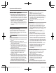
Installation Location Detection range Visual sensor Infrared sensor Can detect motion anywhere in the visible image. Can detect motion only in part of the visible image (shown here in gray) R You can adjust the area detectable by the visual sensor. For more information, refer to the User’s Guide (page 25). R You can adjust the area detectable by the infrared sensor. See “Adjusting the infrared sensor range”, page 21. R Detection does not occur when there are obstacles in front of the infrared sensor.
Installation Location Direction of motion It is easier to detect objects that move sideways in front of the camera, and more difficult to detect objects that move directly toward the front of the camera. A B C D A It is difficult to detect movement directly towards the front of the camera. B It is easy to detect movement sideways in front of the camera.
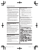
Installation Location Installation location examples I want to detect visitors approaching the house Refer to the table below for detecting visitors at an entrance or gate without detecting cars in the street. Ideal example Poor example 1 1 Approx. 3 m (9.8 feet) Visitors pass in front of the camera from side to side, cars in the street are less likely to cause false detections. 10 Cars in the street are more likely to cause false detections. For assistance, please visit http://shop.panasonic.
Installation Location I want to detect people entering the garage Refer to the table below for detecting people entering a garage without detecting cars in the street. Ideal example Poor example Visitors pass in front of the camera from side to side, cars in the street are less likely to cause false detections. R To prevent faces from being obscured by tall vehicles, adjust the installation position and angle of the camera. Cars in the street are more likely to cause false detections.
Installation Location Do not install in these locations Installing in the following areas may cause deformation, discoloration, malfunction, or operational failure R In direct sunlight or directly under an outdoor light (even if the surroundings are within operational temperature range, parts of the product may become hot) R Areas subject to frequent vibration, shock, or impact R Near fire, heating devices, magnetic fields (such as near magnets), or air conditioners (including outdoor equipment such as uni
Installation Location R Areas affected by breezes from fans, air conditioning unit compressors, water heaters, or car exhaust (severe temperature variations may cause false detections) R Areas subject to severe weather, such as strong wind (camera shake can cause false detections) or rain (strong rain may be detected as an object moving in front of the camera) R Areas with reflective objects, such as glass, that can interfere with detection of temperature variation R Areas where brightness changes easily (
Setup Part names and functions H G I Indicator Status Red, blinking slowly Live images are being viewed or recorded Red, blinking Camera is out of range of the hub, or device malfunction Amber, blinking slowly Camera is not registered to a hub *1 J A B CD E Setup overview F Microphone Sensor range cap (Standard) Infrared sensor LED indicator Lens unit Speaker M N Used when registering the camera to the hub.
Setup Registering the camera This procedure is not required for devices that were included as part of a bundle. Before you can use the camera, it must be registered to the hub. If the camera is not registered to a hub, the camera’s LED indicator blinks slowly in amber. You can register each device by using the registration buttons or the [Home Network] app. Note: R Before registering the camera, make sure the AC adaptors of the hub and camera are connected and each device is powered.
Setup Wall material information Installation Siding Installation precautions R Do not install the camera on a ceiling. R Holes must be made in the wall for cables and wires to pass through. Panasonic takes no responsibility for issues related to opening holes in walls. R Make sure to waterproof the holes you make in the wall. R Make sure you attach the safety wire to prevent the camera from falling. R Do not use an impact driver. (This may lead to damaged screws or over-tightening.
Setup Ideal example Structure supports exterior surface 4 2 Insert the screw and tighten it. 2 2 Camera mounting stand ALC (autoclaved lightweight cellular concrete) 1 1 Siding 2 Structure behind siding Concrete R Do not use the included screws. Use screw anchors (screw ø: 4 mm (5/32 inches)) designed for concrete walls. R Carefully read the instructions supplied with the anchors. Follow instructions regarding drill bit diameter, hole depth, etc. R Drill a pilot hole.
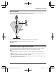
Setup Installing the camera 1 Attach the safety wire to the camera. R Place the ring of the safety wire (A) over the screw hole. R Place a washer (B) on top of the ring of the safety wire. R Tighten the screw (C) for the safety wire on top of the washer. Note: R Use the following template below when determining the location of the screw holes. 37 mm (1 15/32 inches) 37 mm (1 15/32 inches) 3 2 2 1 Attach the camera mounting stand to an outdoor wall.
Setup 3 Attach the camera to the stand using the stand attachment hole on the rear or bottom of the camera, depending on the direction you want to aim the camera. R Loosen the screw (1). R Insert the tip of the stand (A) into the stand attachment hole (B) on the rear or bottom side. R Secure the camera by tightening the screw (2). Attaching to the hole on the rear side 2 1 1 4 Adjust the camera angle. R Loosen the screw (1) and then adjust the camera to the desired angle.
Setup 5 Attach the safety wire to the wall. R Place the ring of the safety wire (A) on the wall. R Place the washer (B) on top of the ring of the safety wire. R Tighten the screw (C) for the safety wire on top of the washer. 3 2 1 6 Connect the DC cable to the AC adaptor. R Pull the DC cable indoors, and connect the DC cable plug (A) to the AC adaptor plug (B). R Connect the AC adaptor (C) to the power outlet. 1 Outdoors 2 Indoors 1 2 1 2 3 Note: R Attach the safety wire while it is bent.
Appendix Testing the motion detection range Adjusting the infrared sensor range After you have installed the [Home Network] app on your mobile device, you can use your mobile device to test the performance of the camera’s motion detection features. For details about these operations, refer to the User’s Guide (page 25). If there are objects that you do not want the infrared sensor to detect, you can adjust the detectable area by attaching sensor range caps.
Appendix Situation and cap types Approximate detection range (view when looking from above) *1 20 °C (68 °F) When you want both sides of the camera to be detectable Standard cap (attached to the camera) When you want one side to be undetectable Cap 1 0 °C (32 °F) 1 2 6 m (19.7 feet) 3 4 m (13.1 feet) (Example) Cap 1 (Example) Cap 1 (Example) Cap 1 1 5 m (16.4 feet) 2 6 m (19.7 feet) 3 4 m (13.1 feet) (Example) Cap 3 (Example) Cap 3 1 1 5 m (16.4 feet) 2 6 m (19.7 feet) 3 4 m (13.
Appendix About the attachment angle of the sensor range cap Example 1 When there is an object on the right side of the viewable area that you do not want to be detected (such as trees): Attach one of caps 1-3 as shown in the example (1) according to the area you do not want to be detected. Example 2 When there is an object on the top left of the viewable area that you do not want to be detected (cars in a street, etc.
Appendix Replacing sensor range caps 1 Remove the attached standard cap. 2 Remove the desired sensor range cap from one of the 4 types (A) and attach it to the sensor (B). R When attaching, rotate the tab (1) on the cap toward the top or at a 45-degree angle according to the type of cap or direction, and attach the cap on the camera, shown in the following illustration. 1 1 2 24 For assistance, please visit http://shop.panasonic.com/support HNC600_(en_en)_0615_ver.130.
Appendix Features available when using the [Home Network] app Accessing the User’s Guide Some of the camera’s features that are available when using the [Home Network] app are listed below. For more information, refer to the User’s Guide (page 25). – Alarm system You can use the app to arm and disarm the alarm system, confirm the current status of the sensor, and view a log of previous events. – Live camera monitoring You can view live images from the camera, even while away from home.
Appendix Specifications R Standards DECT (Digital Enhanced Cordless Telecommunications) R Frequency range DECT: 1.92 GHz – 1.93 GHz R RF transmission power DECT: 115 mW (max.) R Power source 120 V AC, 60 Hz R Power consumption Standby: 2.3 W During operation: 3.1 W (when the LED lights are not lit) 4.5 W (when the LED lights are lit) R Operating conditions -20 °C – 50 °C (-4 °F – 122°F) up to 90 % relative humidity (non-condensing) R Transmitting range Approx. 50 m (160 feet) indoors Approx.
Appendix FCC and other information This device complies with Part 15 of the FCC Rules. Operation is subject to the following two conditions: (1) This device may not cause harmful interference, and (2) this device must accept any interference received, including interference that may cause undesired operation. Privacy of communications may not be ensured when using this device.
Appendix Customer services Shop Accessories! for all your Panasonic gear Go to http://shop.panasonic.com/support Get everything you need to get the most out of your Panasonic products Accessories & Parts for your Camera, Phone, A/V products, TV, Computers & Networking, Personal Care, Home Appliances, Headphones, Ba!eries, Backup Chargers & more… Customer Services Directory For Product Informa"on, Opera"ng Assistance, Parts, Owner’s Manuals, Dealer and Service info go to http://shop.panasonic.
Appendix Limited Warranty (ONLY FOR U.S.A.
Appendix Limited Warranty Limits and Exclusions This warranty ONLY COVERS failures due to defects in materials or workmanship, and DOES NOT COVER normal wear and tear or cosmetic damage.
IMPORTANT! If your product is not working properly. . . A Reconnect the AC adaptor to the camera. B Use the Home Network app to access the User’s Guide and refer to the Troubleshooting section. Visit our Web site: http://shop.panasonic.com/support • FAQ and troubleshooting hints are available. For your future reference We recommend keeping a record of the following information to assist with any repair under warranty. Serial No.
Guía de instalación Sistema de red doméstico Cámara Exterior Modelo n° KX-HNC600 Gracias por adquirir un producto Panasonic. Este documento explica cómo instalar la cámara exterior de forma correcta. Para obtener detalles sobre cómo usar el sistema, consulte la Guía del usuario (página 21). Lea este documento antes de usar la unidad, y guárdelo para consultarlo en el futuro. Para obtener ayuda, comuníquese con nosotros llamando al 1-800-272-7033 o visite nuestro sitio web: http://shop.panasonic.
Tabla de Contenido Ubicación de la instalación Alcance de la comunicación inalámbrica .............3 Información acerca de las características del sensor ..................................................................3 Información acerca del modo de visión nocturna ...............................................................5 Ejemplos de ubicaciones para instalación ...........6 No instale en las ubicaciones siguientes .............8 Configuración Nombres de los componentes y funciones ........
Ubicación de la instalación Alcance de la comunicación inalámbrica El alcance de la comunicación inalámbrica de cada dispositivo en el sistema del hub es de aproximadamente 50 m (160 pies) en interiores y de aproximadamente 300 m (1,000 pies) en el exterior. Es posible que la comunicación inalámbrica no sea tan confiable cuando se encuentran los obstáculos siguientes entre el hub y otros dispositivos.
Ubicación de la instalación Alcance de detección Sensor visual Sensor infrarrojo Puede detectar el movimiento en cualquier parte de la imagen visible. Puede detectar el movimiento solo en la parte de la imagen visible (se muestra aquí en gris) R Puede ajustar el área detectable mediante el sensor visual. Para obtener más información, consulte la Guía del usuario (página 21). R Puede ajustar el área detectable mediante el sensor infrarrojo. Consulte “Ajuste del alcance del sensor infrarrojo”, página 17.
Ubicación de la instalación Dirección del movimiento Es más fácil detectar objetos que se mueven de lado frente a la cámara y es más difícil detectar objetos que se mueven de frente hacia la cámara. A B C D A Es difícil detectar movimiento directamente hacia la parte delantera de la cámara. B Es fácil detectar movimiento lateral frente de la cámara.
Ubicación de la instalación Ejemplos de ubicaciones para instalación Quiero detectar a los visitantes que se acerquen a la casa Consulte la tabla siguiente para detectar a los visitantes en la entrada o puerta sin detectar los vehículos de la calle. Ejemplo ideal Ejemplo incorrecto 1 1 Aprox. 3 m (9.8 pies) Los visitantes pasan en frente de la cámara de lado a lado, y es poco probable que los vehículos en la calle generen detecciones falsas.
Ubicación de la instalación Quiero detectar a las personas que ingresen al garaje Consulte la tabla siguiente para detectar a las personas que ingresen al garaje sin detectar los vehículos de la calle. Ejemplo ideal Ejemplo incorrecto Los visitantes pasan en frente de la cámara de lado a lado, y es poco probable que los vehículos en la calle generen detecciones falsas. R Para evitar que los vehículos altos oscurezcan los rostros, ajuste la posición de instalación y el ángulo de la cámara.
Ubicación de la instalación No instale en las ubicaciones siguientes Si se instala en las áreas siguientes puede provocar deformación, falta de color, errores o fallas de operación R A la luz del sol o bajo una luz exterior (incluso si el entorno está dentro del rango de temperatura funcional, es posible que algunas partes del producto se calienten) R Áreas sujetas a vibraciones, golpes o impactos frecuentemente R Cerca del fuego, calefactores, campos magnéticos (como cerca de imanes) o aires acondicionado
Ubicación de la instalación R Áreas afectadas por brisas de ventiladores, unidades compresoras de aires acondicionados, calentadores de agua o caños de escape de vehículos (es posible que las variaciones fuertes de temperatura generen detecciones falsas) R Las áreas sujetas a malas condiciones climáticas, como vientos fuertes (la cámara puede provocar detecciones falsas al sacudirse) o lluvias (las lluvias fuertes pueden detectarse como objetos en movimiento frente a la cámara) R Áreas con objetos reflecti
Configuración Nombres de los componentes y funciones H G Indicador Estado Rojo, parpadeando lentamente Las imágenes se están visualizando o grabando Rojo, parpadeante La cámara está fuera de alcance del hub o falla el dispositivo Ámbar, parpadeo lento La cámara no está registrada en el hub *1 I Puede configurar la cámara de forma tal que el Led indicador no se encienda durante el funcionamiento normal. Para obtener más información, consulte la Guía del usuario (página 21).
Configuración Cómo registrar la cámara Este procedimiento no es necesario para unidades que son parte de un paquete. Antes de que pueda usar la cámara, se debe registrar en el hub. Si la cámara no se ha registrado a un hub, el Led indicador de la cámara parpadea lentamente en ámbar. Puede registrar cada unidad mediante los botones de registro o la aplicación [Home Network].
Configuración Información sobre el material de instalación Instalación Precauciones de instalación Revestimiento R No instale la cámara en un techo. R Se deben hacer orificios en la pared para que pasen los cables. Panasonic no asume ninguna responsabilidad ante problemas relacionados por abrir orificios en paredes. R Asegúrese de proteger los orificios que haga en la pared contra el agua. R Asegúrese de ajustar el cable de seguridad para evitar que la cámara se caiga.
Configuración Ejemplo ideal La estructura sustenta la superficie exterior 4 2 Introduzca el tornillo y ajústelo. 2 2 Soporte de montaje de la cámara ALC (concreto celular ligero en autoclave) 1 1 Revestimiento 2 Estructura detrás del revestimiento Concreto R No use los tornillos incluidos. Use los taquetes (tornillos de ø: 4 mm (5/32 pulgadas)) diseñados para paredes de concreto. R Lea con atención las instrucciones suministradas con los taquetes.
Configuración Nota: R Utilice la siguiente plantilla cuando determine la ubicación de los orificios de los tornillos. Cómo instalar la cámara 1 Coloque el cable de seguridad en la cámara. R Coloque la terminal circular del cable de seguridad (A) sobre el agujero para el tornillo. R Coloque una arandela (B) encima de la terminal circular del cable de seguridad. R Ajuste el tornillo del cable de seguridad (C) encima de la arandela.
Configuración Colocación en el orificio en la parte inferior 2 1 1 5 Coloque el cable de seguridad en la pared. R Coloque la terminal circular del cable de seguridad (A) sobre la pared. R Coloque la arandela (B) encima de la terminal circular del cable de seguridad. R Ajuste el tornillo del cable de seguridad (C) encima de la arandela. 2 4 Ajuste el ángulo de la cámara. R Afloje el tornillo (1) y, a continuación, ajuste la cámara según el ángulo que desee.
Configuración 6 Conecte el cable de CC al adaptador de corriente. R Hale el cable de CC interior y conecte el enchufe de cable de CC (A) al enchufe del adaptador de corriente (B). R Conecte el adaptador de corriente (C) a la toma de corriente. 1 Exterior 2 Interior 1 2 1 2 3 Nota: R Use solo el adaptador de corriente alterna Panasonic PNLV236 que se suministra. R Asegúrese de conectar el enchufe del cable de CC y el enchufe del adaptador de corriente interiores.
Apéndice Cómo probar el alcance de detección de movimiento Ajuste del alcance del sensor infrarrojo Después de instalar la aplicación de [Home Network] en su dispositivo móvil, puede usarlo para probar el funcionamiento de las características de detección de movimiento de la cámara. Para obtener más detalles sobre estas operaciones, consulte la Guía del usuario (página 21).
Apéndice Situación y tipos de tapas Alcance de detección aproximado (vista desde arriba) *1 20 °C (68 °F) Cuando desea que se detecten ambos lados de la cámara Tapa estándar (colocada en la cámara) Cuando desea que se detecte solo un lado Tapa 1 0 °C (32 °F) 1 30 °C (86 °F) 3 2 1 5 m (16.4 pies) 2 6 m (19.7 pies) 3 4 m (13.1 pies) (Ejemplo) Tapa 1 (Ejemplo) Tapa 1 (Ejemplo) Tapa 1 1 3 2 Tapa 2 1 5 m (16.4 pies) 2 6 m (19.7 pies) 3 4 m (13.
Apéndice Acerca del ángulo de colocación de la tapa de alcance del sensor Ejemplo 1 Cuando hay un objeto en el lado derecho del área visible que no quiere que se detecte, (como árboles): Coloque una de las tapas 1-3 como se muestra en el ejemplo (1) de acuerdo con el área que no desea que se detecte. Ejemplo 2 Cuando hay un objeto en el extremo superior izquierdo del área visible que no desea que se detecte (vehículos en la calle, etc.
Apéndice Reemplazo de las tapas de alcance del sensor 1 Extraiga la tapa estándar ya colocada. 2 Retire la tapa de alcance del sensor deseado de uno de los 4 tipos (A) y colóquelo en el sensor (B). R Al instalar, gire la pestaña (1) en la tapa hacia arriba o a un ángulo de 45-grados de acuerdo con el tipo de tapa o dirección y coloque la tapa de la cámara, como se muestra en la siguiente ilustración. 1 1 2 20 Para obtener ayuda, visite http://shop.panasonic.com/support HNC600_(es_es)_0623_ver.130.
Apéndice Acceso a la Guía del usuario La Guía del usuario es una colección de documentación en línea que lo ayuda a aprovechar al máximo la aplicación [Home Network]. 1 iPhone®/iPad® Toque en la pantalla de inicio de la aplicación. Dispositivos Android™ Toque u oprima el botón menú de su dispositivo en la pantalla de inicio de la aplicación. 2 Toque [Guía del Usuario]. Nota: R No se admite Microsoft® Windows® Internet Explorer® 8 y versiones anteriores. R Se recomienda Android 4.