
Datasheet


SR-DSV10739− 25-10 −
MINAS-A5 Vol.1 Motor Business Unit, Appliances Company, Panasonic Corporation.
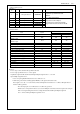
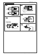
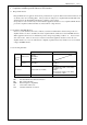
Functions allocatable to Multi-function outputs
Name Symbol
Pin
Description
Servo alarm ALM
8
- Digital output to indicate alarm status.
Servo ready S-RDY 10 - AMP turn on electricity signal
Motor holding break release
BRK-OFF
- - Digital output to provide the timing signal to control the motor
holding brake.
Zero speed ZSP - - Digital output to indicate the zero speed status.
Torque limited TLC - - Digital output to indicate the torque is limited.
In- INP
9
- Digital output to indicate the in-position status.( INP)
In-position 2 INP2
-
- Digital output to indicate the in-position status.( INP2)
Warning output1
WARN1
-
- Digital output to indicate the warning output signal status. Set by
Pr4.31 "warning output 1"
Warning output2
WARN2
-
- Digital output to indicate the warning output signal status. Set by
Pr4.32 "warning output 2"
position command output
P-CMD
- - Digital output to indicate position command
Alarm attribute output
ALM-ATB -
- Digital output to Alarm which can be cleared.
Main Power output
P-ON
- - Digital output to voltage which exceed to the level voltage of Serv
o on.
- initial setting use
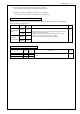
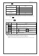
Default setup
Input signal
Applicable
parameter
Default setting
():10decimal notation
Title of
signal
Logic
SO1 output Pr4.00
00000003h
(3)
SRV-ON a-contact
SO2 output
Pr4.01
00000004h
(4)
A-CLR a-contact
SO3 output
Pr4.02
00000007h
(7)
CL a-contact
-Change signal layout use
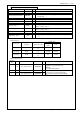
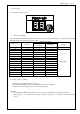
Classificat
ion
No. Parameter Title Set range Unit
Function
4
10
SO1 output selection
0∼00FFFFFFh
-
Assign function to SO1 output.
this parameter is presented in hexadecimal.
000000**h
「**」with the function number.
4
11
SO2 output selection
0∼00FFFFFFh
-
4
12
SO3 output selection
0∼00FFFFFFh
-
Assign functions to SO2 to SO3 outputs.
These parameters are presented in hexadecimals.
Setup procedure is the same as described for Pr.4.00.