AC Servo Motor Driver MINAS S-series Operating Manual Be sure give this instruction manual to the user. • Thank you very much for your buying Panasonic AC Servo Motor Driver,A-series. • Before use, read through this manual to ensure proper use. Keep this manual at an easily accessible place so as to be referred anytime as necessary.
Table of Contents Before Use Safety Precautions ••••• 4 Introduction ••••••••••••• 8 Parts Description ••••••••••• 12 Amplifier ••••••••••••••••••••••••••••••••••••• 12 Motor ••••••••••••••••••••••••••••••••••••••••• 13 After Opening the Package •••••••••••••••• 8 Check the Model Number of Amplifier •••••••••••••••••• 8 Check the Model Number of Motor ••••••••••••••••••• 9 Check the Combination of Amplifier and Motor ••••••••••••••••••••• 10 Installation ••••••••••••••••• 14 Amplifier •••••••••••••••••••
Important Information Troubleshooting •••••••••••••••••••••••••••••• 68 After-Sale Service •••••••••••••••••••••• Back cover Protective Functions ••••••••••• 60 Maintenance and Inspections ••••••••••• 6 6 Appendixes Conformance to EC Directives and UL Standards ••••••••••• App. 2 Holding Brake ••••••••••••••••••••••••• App. 6 Dynamic Brake •••••••••••••••••••••••• App. 8 Timing Chart ••••••••••••••••••••••••• App. 10 Acceptable Loads on Output Shaft ••••••••••••••• App.
Safety Precautions (Important) Observe the following precautions in order to avoid injuries of operators and other persons, and mechanical damages. The following DANGER and CAUTION symbols are used according to the level of dangers possibly occurring if you fail to observe the instructions or precautions indicated. DANGER CAUTION Indicates a potentially hazardous situation which, if not avoided, will result in death or serious injury.
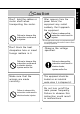
Don't subject the product to water splash, corrosive gases, flammable gases and combustible things. Don't touch the rotating part of the motor in motion. Failure to observe this instruction could result in fire. Rotating part Failure to observe this instruction could result in injuries. Perform the transportation, wiring and inspection at least 10 minutes after the power off. Do not expose the cables to sharp edges, excessive pressing forces, heavy loads or pinching forces.
Safety Precautions (Important) Caution Use the motor and amplifier in the specified combination. Execute the trial operations with the motor fixed but without motor load connected. Connecting a load to the motor is possible only after successful trial operation. Failure to observe this instruction could result in injuries. Failure to observe this instruction could result in fire. Don't touch the motor, amplifier or its regenerative discharge resistor, since they become hot.
After recovery from the power failure, the equipment may restart suddenly. Don't approach the equipment Don't hold the cables or motor shaft when transporting the motor. Failure to observe this instruction could result in injuries. Failure to observe this instruction could result in injuries. *Provide appropriate settings as a preparedness against the accidental restart of the machine in order to ensure the safety of personnel. Don't block the heat dissipation hole or insert foreign matters in it.
Introduction After Opening the Package • Make sure that the product is what you have ordered. • Check whether the product has been damaged or not during transportation. If the product is not correct, or it has been damaged, contact dealer or sales agent. Check the Model of Amplifier Name plate AC SERVO DRIVER Model Rated input voltage Rated motor output Model No. MUDS3A1A1A INPUT OUTPUT ENCODER Voltage 100-115V 32V 2500P/R Phase 1ø 3ø F.L.C 1.0A 1.0A Freq. 50/60Hz 0~333.
Before Use Check the Model of Motor Name plate Type AC SERVO MOTOR Model No. MUMS042A1A INPUT 3ØAC 92 V 1.6 A RATED OUTPUT 0.2 kW Hz RATED FREQ. 200 RATED REV. 3000 r/min Rated output Revolution rating CONT. TORQUE 0.64 Nm RATING S1 INS. CLASS B (TÜV) A (UL) IP65 CONNECTION SER No. 00010001 Serial No MatsushitaElectric Industrial Co..Ltd.
Introduction Check the Combination of Amplifier and Motor The amplifier has been designed for use in combination with the specified motors only. Check the specifications (Series symbol, output rating, voltage rating and encoder type) of the motor you want to use.
With the incremental type encoder: 2500P/r 100V Amplifier type Super MUDS011A1A MUDS021A1A Type2 MUDS041A1A Type3 Type2 Type3 3-phase/1- MUDS3A5A1A Type1 MUDS5A5A1A MUDS015A1A 3-phase, MUDS023A1A 200V MUDS043A1A MUDS083A1A Motor type **** **** MUMS011A **** MUMS021A **** MUMS041A **** MUMS022A **** MUMS042A **** MUMS3AZA **** MUMS5AZA **** MUMS012A **** MUMS022A **** MUMS042A **** MUMS082A **** Voltage Type1 MUMS MUMS3AZ MUDS5A1A1A 1-phase, MUDS022A1A 200V MUDS042A1A phase, 200V Motor Ser
Parts Description Amplifier Example: MUDS023A1A (3-phase, 200V 200W: Type 1) MSDS Example: MUDS042A1A (1-phase, 200V 400W: Type 3) STATUS MSDS ALM CODE STATUS Status LED Alarm code LED ALM CODE GAIN Communication connector CN SER CN SER Main power input connector (L1, L2, L3,P, B) Controller connection (CN I/F) CN I/F CN POWER Motor connection (U, V, W, E) Encoder connection (CN SIG) CN SIG Earth connections CN MOTOR GAIN Rotary switch for gain (GAIN) tuning CN SER CN I/F CN POWER CN
Example: Super Low-Inertia Motor (MUMS Series, 400W) Encoder cable Motor cable Encoder Brake cable (Motor with electromagnetic brake only ) Frame Mounting bolt holes (4) Flange For detailed information for each of motor types, see the drawings in the Appendix (App.48 & 49).
Installation The amplifier and motor should be properly installed to avoid failures, mechanical damages and injuries. Amplifier Location • Indoors, where the amplifier is not subjected to rain water and direct sun beams. Note that the amplifier is not a waterproof structure. • Avoid the place where the amplifier is subjected to corrosive gases, flammable gases, grinding liquids, oil mists, iron powders and cutting particles. • Place in a well-ventilated, and humid- and dust-free space.
• Allow enough space to ensure enough cooling. • Install fans to provide a uniform distribution of temperature in the control box. The airflow of fan is more than 0.43m3/min. And it should be located 10 cm away from the amplifier. • Observe the environmental requirements for the control box, mentioned in the previous page.
Installation Motor Location • Indoors, where the amplifier is not subjected to rain water and direct sun beams. • Avoid the place where the amplifier is subjected to corrosive gases, flammable gases, grinding liquids, oil mists, iron powders and cutting particles. • Place in a well-ventilated, and humid- and dust-free space. • Easy maintenance, inspections and cleaning is also important.
• Make sure that the cables are not subjected to moments or vertical loads due to external bending forces or self-weight at the cable outlets or connections. • In case the motor is movable, secure the cable (proper one supplied together with the motor) to a stationery part (e.g. floor), and it should be extended with an additional cable which should be housed in a cable bearer so that bending stresses can be minimized. • Make the bending radius of cables as large as possible.
System Configuration and Wiring General Wiring Diagram • Main Circuits Non-Fuse Breaker (NFB) Used to protect the power lines: overcurrent will shut off the circuit. Noise Filter (NF) Prevents the external noise from the power line, and reduces the effect of the noises generated by the servo motor. Magnetic Contactor (MC) Turns on/off the main power of the servo motor. Used together with a surge absorber. Reactor (L) Reduces the harmonic current in the main power.
Communication control software PANATERM“ STATUS ALM CODE 1 5 6 8 9 0 7 GAIN 2 3 4 CN SER CN SER (to connect a PC or controller) CN I/F CN POWER CN I/F (to connect a controller) CN SIG CN SIG CN MOTOR (to connect an encoder) Encoder cable 1234 1234 1234 Hazardous Voltage Others; Low Voltage circuit Motor cable Power supply for motor brake (24VDC) -19- Preparations and Adjustments Personal computer
System Configuration and Wiring List of Available Components Amplifier Required Power Series Voltage Output 30 ~ 50W (at the rated load) Circuit breaker (rated current) Noise Magnetic contactor filter (contacts) Main circuit wire diameter (L1, L2, L3, U, V, W, E) Approx. 0.3kVA B K 2 5 1 D V O P 1 4 4 1 B M F T 6 1 0 4 1 N 1-phase, 1 0 0 W Approx. 0.4kVA ( 5 A ) 1 0 0 V 2 0 0 W Approx. 0.5kVA (3P+1a) 4 0 0 W Approx. 1.
For 3-phase 200VAC 3-phase 200V ON MC MC NFB MC Noise filter OFF L 10 8 6 5 172167-1 172159-1 tyco Electronics AMP Red White or yellow Black Green/yellow 3 tyco Electronics AMP L1 P L2 N L3 P P B N 5557-10R-210 1 1 4 2 6 3 3 4 U V W E Motor 9 ALM ALM VDC 12~24V 13 COM – For 1-phase 100V/200V Single-phase 100V or Single-phase 200V ON MC MC NFB MC Noise filter OFF L 10 L1 P L2 6 5 172167-1 172159-1 tyco Electronics AMP 3 tyco Electronics AMP 5557-10R-210 Red Whit
System Configuration and Wiring Main Circuits Always ask to an electric engineer for wiring. Don't turn on the main power until the wiring and connectings are completed, to avoid electric shocks. Wiring Instructions • Make necessary connections. For wire diameter, see List of Available Components (page 20). • Securely insert connectors. See the nameplate of the amplifier to check the power specification. Install a non-fuse breaker or leakage breaker.
CN SIG Connector (For Encoder) Wiring Instructions MSDS The cable length between the amplifier and motor should be max. 20 m. If you use a longer cable, contact the dealer or sales agent. POWER ALARM Power GAIN RS232C CN I/F CN POWER Encoder Motor min.30cm max.
System Configuration and Wiring CN SER Connector For RC232C communications Connect a personal computer to the amplifier with RS232C at 1:1, and use the communication control software "PANATERM “ " (Option). Operate "PANATERM “ " on the personal computer. Convenient functions of high operability can be obtained such as monitor and parameter setting and setting change and waveform graphic display. Connection MSDS STATUS ALM CODE Exclusive connection cable (Option) See App. 44.
List of Available Components CN I/F Connector (For Controller) Wiring Instructions Place the peripheral devices such as the controller max. 3 m away from the amplifier. max. 3 m MSDS Controller POWER ALARM GAIN RS232C min.30 cm CN SIG CN MOTOR Motor The control power (VDC) between COM+ and COM- should be supplied by the customer (recommended voltage: +12VDC to +24VDC). COM+ 1 2 GND Use a shielded twist-paired type for the wiring of pulse input, encoder signal output, etc.
VDC 12~24V 5 10 In-position - 26 - Alarm (Pr09) COIN ALM 26 13 FG COM- 12 WARN 11 BRKOFF 9 Mechanical brake release DIV GAIN 7 CWL 8 CCWL Servo alarm CCW overtravel inhibit CW overtravel inhibit Command pulse scaler switch 6 2nd gain switching CL 1 COM+ 2 SRV-ON 3 A-CLR Position error counter clear 4 Alarm clear Servo-ON • CN I/F Wiring for Position Control CN I/F Scaler 4.
VDC 12~24V 26 FG COM- 12 WARN 13 Alarm (Pr09) COIN ALM 11 BRKOFF 10 9 CN I/F Scaler 3 A-CLR 4 INTSPD2 5 ZEROSPD 6 INTSPD1 7 CWL 8 CCWL 4.7kΩ 1 COM+ 2 SRV-ON Mechanical brake release At-speed Servo alarm CCW overtravel inhibit CW overtravel inhibit Internal vel .cmnd.select 1 Speed zero clamp Internal vel .cmnd.
System configuration and wiring CN I/F Connector Input Signals (Common) and their Functions Signal Control signal power (+) Control signal power (-) Servo-ON Alarm clear Pin No. 1 Symbol Function C O M Å { • Connect to (+) of an external power supply(12VDC to 24VDC). I/F circuit Å\Å\ • Use power supply of 12V±10%Å`24V±10% 1 3 C O M Å | • Connect to (-) of an external power supply(12VDC to 24VDC). •The required capacity depends on the I/O circuit configuration. 0.5A or larger is recommended.
Signal Gain switching/ Speed zero clamp Pin No. 5 Symbol Function GAIN/ The function differs depending on the control mode. ZEROSPD I/F circuit SI page 33 • The functions depend on the value of Pr30. • Gain switching input results. Input for switching PI/P Position control Internal velocity control (Default) Close 1 Open Close Preparations and Adjustments operation and No. 1/No. 2 gains.
System configuration and wiring Signal CW overtravel Pin No. 7 Symbol CWL inhibit CCW overtravel inhibit 8 CCWL I/F circuit • If COM- is opened when the movable part of the SI machine has moved to CW exceeding the limit, the page 33 Function motor does not generate torque. • If the COM- is opened when the movable part of the SI machine has moved CCW exceeding the limit, the page 33 motor does not generate torque. • When Pr04 (Overtravel Limit Input Disabled) = 1, CWL and CCWL inputs are disabled.
Output Signals (Common) and their Functions Symbol Servo alarm Pin No. 9 ALM I/F circuit • This output (transistor) turns off, when the S O 1 detector detects an alarm. page 34 In-position/ 1 0 COIN • The function differs depending on the control S O 1 Signal mode. At-speed • Output(transistor) turns ON when the position error is below the preset value by Pr60 (In-Position Range). Internal velocity • At-speed.
System configuration and wiring Pin No. 1 5 1 6 Symbol OA + OA - I/F circuit • Provides differential outputs of the encoder signals P O 1 (A, B and Z phases) that come from the divider page 34 B-phase output 1 7 1 8 OB + OB - (equivalent to RS422 signals). • The logical relation between A and B phases can be selected by Z-phase output 1 9 2 0 OZ + OZ - Pr45 (Output Pulse Logic Inversion).
CN I/F Connector Interface Circuit (Input Circuit) SI Connecting to sequence input signals • Connect to a contact of switch and relay, or a tran- 12~24V 1 COM+ 4.7kΩ VDC Servo-ON or other input Relay sistor of an open collector output. • Can be used with COM- instead of COM+ Servo-ON or other input 12~24V Relay VDC 1 COM+ 4.7kΩ Available at reverse polarity PI Command pulse input circuit 1) AM26LS31or equivalent 23 1) Line Amplifier I/F 25 less sensitive to noises.
System configuration and wiring Interface Circuit (Output Circuit) S O 1 Sequence output circuit Install as per the fig. shows without fail • This comprises a Darlington amplifier with an open collector. This is connected to a relay or photo coupler. SO1 ALM • There exists a collector-to-emitter voltage VCE(SAT) of approx. 1.2V at 12~24V transistor ON, because of Darlington connection of the output transistor.
P O 2 Open Collector Output Maximum rating: 30V, 50mA • Outputs Z-phase signals among those from the encoder. The outputs are noninsulated. • Receive these signal with high-speed photo coupler at controller side, since these Z-phase signal width is normally narrow. 19 CZ 14 GND shows a pair of twisted wires. CN MON Connector Monitor Circuit (Output Circuit) A O Analogue Monitor Output • Output from CN MON Connector • This output is the velocity monitor signal (SP) or torque monitor signal (IM).
Parameter Setting Overview The servo amplifier has various parameters that are used for adjusting or setting the features or functions of the amplifier. This section describes the purpose and functions of these parameters. Understanding these parameters is essential for obtaining the best, application-specific operation of the amplifier. You can view, set and adjust these parameters using your personal computer with the communication software PANATERM “ . Parameter Groups and Listing ParameterNo.
Parameters for Selecting Function Parameter NO.
Parameter Setting Parameters for Defining the Real Time Auto Gain Tuning Parameter No. (Pr**) Parameter description Åñ2 0 Inertia ratio Åñ2 Åñ2 1 2 Real time auto tuning set-up Åñ2 3 24~2F Machine stiffness at auto tuning (Not available) (Internal use) Range Default Unit 0 ~ 10000 100 % 0~3 0~9 0 2 --------- --------- 100 0 --------- Parameters for Adjustments (for 2nd Gain) Parameter No.
Parameters for Position Control Parameter No.
Setting the Parameters Parameters for Sequence Parameter No (Pr ) Parameter description Range Default Unit Åñ6 0 In-position range 0 ~ 32767 1 0 Pulse Åñ6 Åñ6 1 2 Zero speed 0 ~ 10000 0 ~ 10000 5 0 1000 r/min r/min Åñ6 Åñ6 3 4 Position error set-up 0 ~ 32767 0~1 1875 0 256Pulse Position error invalidation Åñ6 Åñ6 5 6 (Internal use) Dynamic Brake inhibition at overtravel limit -----0~1 1 0 ----------- Åñ6 7 (Internal use) ------ 0 ------ Åñ6 Åñ6 8 9 Sequence at alarm Seq
Setting the Parameters • You can set the Parameters with your personal computer with the S-series communication software PANATERM“. For the use of PANATERM“ for parameter handling, see the instruction manual of the software. You can conduct the following operations using PANATERM“: 1) Setting the Parameters for amplifier, storing them, and writing in the memory (EEPROM) 2) Monitoring input/output status, monitoring pulse input, monitoring load ratio.
Setting the Parameters Installing PANATERM “ on a hard disc 1. The memory capacity of the hard disc should be 15MB or more. Prepare OS of Windows “ 95 or Windows“98. 2. Install PANATERM “ with setup discs, otherwise the software does not work. Procedure 1) Turn on your personal computer. Start Windows“95 (or 98). (If there is any application program on, close all of them.) 2) Insert the PANATERM“ setup floppy disk in the floppy disk drive.
Starting PANATERM“ 1. Once you install PANATERM “ on your hard disc, you do not have to install it again for next use. 2. Before using PANATERM “ , the amplifier, power supply, motor and encoder should be connected. For the procedure for starting PANATERM “ , see the Windows “ manual . Procedure 2) Turn on the amplifier. 3) Click on the start button of Windows“ (see the Windows“ manual). 4) Select (click on) PANATERM“ from the program menu.
Trial Run Inspections before Trial Run 1) Inspecting the wiring • Make sure that all wire connections (especially main power and motor output ) are correct. • Make sure that there is no short, and earth wires are properly connected. • Make sure that there is no poor connections. 2) Inspecting the power specifications • Make sure that the voltage is correct.
Operation with CN I/F Connected 1) Connect CN I/F. 2) Connect the control signal (COM+/-) to the power supply (12 to 24V DC). 3) Turn the main power (amplifier) ON. 4) Check the defaults of the parameters. Control mode setting (Pr2 value: 0). 5) Connect between SRV-ON (CN I/F pin 2) and COM- (CN I/F pin 13) to make Servo-On active. The motor will be kept excited. 1) Set Pr42 (Command Pulse Input Mode Set-Up) according to the output form of the controller. Then write it down to EEPROM.
Trial Run Set-up of motor speed and input pulse frequency Input pulse Motor Pr 4A x2 Pr 46 frequency speed Pr 4B (pps) 500k (r/min) 3000 2500P/r 0 x 2 10000 10000 250k 3000 10000 100k 3000 10000 500k 1500 0 x 2 5000 0 x 2 2000 5000 x 2 0 10000 * You can set any value by setting any value for the numerator and denominator. However, the motor action will not follow the extreme setting of the ratio. It is recommended to set within a range from 1/50 to 20.
Test Run at Internal Velocity Control Mode 1) Select the internal velocity control mode (Pr02: 1) for the control mode. 2) Run with zero speed clamp input (ZEROSPD) (5 pin) switch close, and rotate the motor with the combination of the internal command speed selection INTSPD 1 (6 pin) and INTSPD 2 (4 pin). 3) Check the motor speed on the PANATERM“ monitor. ÅE Speed and direction 4) Make sure that the motor stops by making zero speed clamp input (ZEROSPD) open. in Appendix 31.
Trial Run Fundamental Operations and LED Indications 1. Turn on the power.
2.Check LED status. LED color Meaning Green Main power is on. Amplifier power is on. Orange Flashing when warning occurs. (Overload, excessive regenerative energy) Red Alarm (Under the normal operation, the alarm indicator is OFF.) This indicator will start flashing when an alarm occurs. Alarm codes (see page 60-65) are indicated by the number of flash (in orange and red) Orange: Tens digits, Red: Unit digits Set the rotary switch to default "0" position for GAIN adjustment.
Adjustments Purposes of Gain Adjustment In case of the servo motor, the motor is required to act per any command without any time delay, or without missing any commands. To ensure this, gain adjustment is necessary. Gain set-up: low +Feed forward set-up Gain set-up: high +2000 +2000 0 0 Actual velocity Command Speed -2000 -2000 {r/min} {r/min} 0.
Applicability of Automatic Adjustment Item Load inertia Conditions • Must be at least three times as large as the motor inertia, but not greater than 20 times. • Must not fluctuate much Load • The machine (motor load) and its coupling must have a higher mechanical stiffness. • The backlash of the gears and other equipment must be small. • Eccentric load must be smaller than one-fourth of the rated torque. • The viscous load torque must be smaller than one-fourth of the rated torque.
Adjustments How to Adjust Gain Start Turn gain adjustment rotary switch GAIN CW. · Adjust setting to value suitable for machine configuration. · For table of rotary set values and machine configuration, see page 58. No Actioon OK? Abnormal sound or vibration occurs. Return gain adjustment rotary switch GAIN to original position. (Turn CCW.) OK Action OK? NG Adjust gain adjustment rotary switch to "0" position. No Automatic adjustment (automatic gain tuning) · Setting by PANATERM® is required.
How to Use "Normal Auto-Gain" Tuning Automatic tuning is available when the gain adjustment rotary switch GAIN is set to "0" position only. 1) Start PANATERM“, and click on "Auto tuning" in the window menu to open the automatic tuning screen. 2) Move the bar for mechanical stiffness to set the stiffness.To start from smaller value (1).
Adjustments How to Use "Real Time Auto-Gain" Tuning Automatic tuning is available when the gain adjustment rotary switch GAIN is set to "0" position only. 1) Start PANATERM“, and go to Parameter Set-up Mode. 2) Set Pr1F (Disturbance torque observer) to 8 (invalid). 3) Set Pr22 (Real time auto tuning machine stiffness).
How to Adjust Gain Manually Before Adjustment You may adjust the gains by viewing or hearing the motions and sound of the machine during operation. But, to adjust the gains more quickly and precisely, you can obtain quicker and secure adjustment by analog wave form monitoring. 1. Wave form graphic function of PANATERM “ You can view the graphic information of the command to the motor, actual motor action (speed, torque and position error) on the computer display screen. 2.
Adjustments How to Adjust the Gain at Position Control Mode 1) Input the inertia ratio of Pr20. For horizontal axis, take measurements on the basis of "Normal auto tuning". For vertical axis, obtain values through calculations. 2) Conduct adjustments with the parameters shown in the following table taken as guidance values. Parameter No. Pr10 Parameter description 1st position loop gain Guidance value 50 Concept of adjustment OK, if there is no problem with the motion.
How to improve the response further You can manually adjust the 2nd gain. With the 2nd gain adjustment, you can expect quicker response. When you want to reduce the noise produced during the stopping (servo-locking), you set the lower gain after the motor stops. Parameter No.
Adjustments Gain Tuning Using Gain Adjustment Rotary Switch Set the rotary switch depending on machine configuration. Then while checking movement of machine, in- For increasing gain crease the rotary switch value one by one. 7 8 4 0 1 5 6 9 Note When the number gets larger, gain will be increased. 2 3 For lowering gain *Do not operate rapid change of the value such as 9 to 0 or 0 to 9. Otherwise the motor will oscillate, which results in abnormal sound and vibration.
To reduce the mechanical resonance P r 1 D Notch frequency Pr1E Notch width selection Set this about 10% lower than the resonance frequency measured by the frequency characteristics analysis function of PANATERM “ . Gain Notch Frequency Use the default value of 2. How to measure the resonance frequency of a machine system 1) Log-on PANATERM “ and open the frequency characteristics screen. 2) Set the following parameters and measuring conditions. Note that the values shown below are only guidance.
Protective Functions What are the Protective Functions? The amplifier has various protective functions. When one of the protections is activated, the motor trips according to the timing chart shown in "Error Handling" in Appendix, and the Servo Alarm Output (ALM) is turned off. Actions to be taken after trip events • After a trip event, the status LED (STATUS) on the front panel will be turned in red, and the alarm code LED display (ALM CODE) will start flashing. No servo-ON occurs.
Protective Functions: Causes and Corrections Protection Alarm Code No. Countermeasures Cause Undervoltage 1 1 The P-N voltage of the main power Measure the terminal-to-terminal voltconverter is lower than the specified age (between L1, L2 and L3). voltage during Servo-ON. 1) Increase the capacity of the main power or replace it with a larger one. 1) The main power line voltage is too low. Or remove the causes of the failure An instantaneous outage occurred.
Protective Functions Protection *Overcurrent error Cause Countermeasures The current flowing in the converter is larger than the specified value. 1) The amplifier failed (due to defective circuits or IGBT parts). 2) Motor wires (U, V and W) are shorted. 3) Motor wires are grounded. 4) Motor burned 5) Poor connection of Motor wires 6) The relay for the dynamic brake is melted and stuck due to the frequent Servo-ON/OFF. 7) The motor is not compatible with the amplifier.
Protection Overload error Alarm Code No. Cause Countermeasures 1 6 Overload protection is activated via Check on waveform graphic screen of the specified time limiting operation P A N A T E R M “ w h e t h e r t h e t o r q u e when the integration of a torque com- ( c u r r e n t w a v e ) i s s u r g i n g o r n o t . mand exceeds the specified overload Check the overload alarm message level. and load factor using PANATERM “ .
Protective Functions Protection Alarm Code No. Cause Countermeasures * Encoder A/ 2 0 B-phase error No encoder A- and B-phase pulse is de- Correct the encoder wiring per the wiring tected. The encoder failed. diagram. Correct the connection of the pins. 2 1 * Encoder communication error Due to no communication between the encoder and amplifier, the detective function for broken encoder wires is activated.
Protection Alarm Cause Countermeasures CodeNo. Error counter 2 9 The value of the position error counter is Check that the motor operates per the o v e r 227 ( 1 3 4 2 1 7 7 2 8 ) . over flow position command pulse. See the torque monitor to check that the output torque does not get saturated. Readjust the gains. Maximize the value of Pr5E (torque limit setup). Correct the encoder wiring. * EEPROM parameter error 3 6 The data contained in the parameter stor- Set all the parameters again.
Maintenance and Inspections E Å Routine maintenance and inspections are essential for proper and satisfactory operation of the amplifier and motor. Notes to Maintenance/Inspections Personnel 1)Power-on/off operations should be done by the operators themselves. 2)For a while after power off, the internal circuits is kept charged at higher voltage. Inspections should be done a while (about 10 minutes), after the power is turned off and the LED lamp on the panel is extinguished.
Replacement Guidance Parts replacement cycles depend on the actual operating conditions and how the equipment has been used. Defective parts should be replaced or repaired immediately. Dismantling for inspections or repairs should be done by our company (or our sales agents).
Troubleshooting The motor does not rotate.
The motor does not rotate. Category Parameters Wiring Installation Countermeasures Causes The control mode selected is not Check the value of Pr02 (control mode set-up). correct. 0: position control, 1: internal velocity control, The torque limit has been set to 0. Check the value of Pr5E (torque limit set-up). Change the value to 300 (default). The zero speed clamp is ON, so Check the value of Pr06 (ZERPSPD input selection). the motor does not operate. Change the value to 0.
Troubleshooting The rotation is not smooth. Category Adjustment Causes The gains are not appropriate. Countermeasures Increase the value of Pr11 (1st velocity loop gain). Set a torque filter (Pr14) and then further increase the value of Pr11. P o s i t i o n c o m m a n d s a r e n o t Check the behavior of the motor on the waveform graphic screen of PANATERM“ using the CN MON check pin. Check the wiring and its connections. Check the controller.
Positioning accuracy is bad. Category System Countermeasures Causes Position commands (amount of Count the number of feedback pulses on the monitor command pulses) are not cor- screen of PANATERM “ while repeating travel to back and forth within a fixed distance. If the number of rect. feedback pulses varies, adjust the controller. Take measures to reduce the noise on the command pulse.
Troubleshooting The initial (home) position varies. Category System Causes Countermeasures W h e n c a l c u l a t i n g t h e i n i t i a l Check that the Z-phase accords to the center of ( h o m e ) p o s i t i o n , t h e Z - p h a s e the proximity dog. Perform initialization correctly output is not detected. according to the controller. Creep speed to initial position is Decrease the return speed near the initial (home) too high. Wiring position, or lengthen the initialization sensor.
The motor produces an abnormal sound and/or vibration. Category Adjustment Causes The gains are too large. Countermeasures Decrease the values of Pr10 (position loop gain) and Pr11 (velocity loop gain).Change the value of rotary switch gain. The velocity detection filter is Increase the value of Pr13 (speed detection filter) until the sound decreases to an acceptable level, or not proper. Installation return the value to 4 (default).
Troubleshooting Overshoot or undershoot The motor overheats (burnt) Category Adjustment Installation Causes Countermeasures Gains are not correct. Check the gains using the wave form graphics monitoring function of PANATERM“ , speed monitor (SP) and/or torque monitor (IM). Adjust the gains. See "Adjustments" chapter. Load inertia is too large. Check the load inertia using the wave form graphics monitoring function of PANATERM “ , speed monitor Check the coupling between the motor and machine.
Appendixes Conform to EC Directives and UL Standards Holding brake ○ ○ Dynamic brake Timing chart ○ ○ ○ ○ ○ ○ ○ ○ ○ ○ ○ ○ ○ ○ ○ ○ ○ ○ ○ ○ ○ ○ ○ ○ ○ ○ ○ ○ ○ ○ ○ ○ ○ ○ ○ ○ Allowable loads on output axes ○ Details of Parameters ○ ○ ○ ○ ○ ○ ○ ○ ○ ○ ○ ○ ○ ○ ○ ○ ○ App. 10 ○ ○ ○ ○ ○ ○ ○ App. 8 ○ ○ ○ App. 6 ○ ○ ○ App.
Conformance to EC Directives and UL Standards EC Directives The EC Directives apply to all such electronic products as those having specific functions and directly sold to general consumers in EU countries. These products are required to meet the EU unified standards and to be furnished with CE Marking. However, our AC servos meet the EC Directives for Low Voltage Equipment so that the machine or equipment comprising our AC servos can meet relevant EC Directives.
Peripheral Equipment Environment The servo amplifier should be used under Contamination Level 2 or 1 specified by IEC606641 (housing the amplifier in an IP54 control box).
Conformance to EC Directives and UL Standards Surge Absorber Install a surge absorber at the primary side of the noise filter. When performing a voltage-resisting test, remove the surge absorber. Otherwise the absorber may be damaged. Install noise filters. Install noise filters (specially designed for signal wires) for all cables (power, motor, encoder and interface wires).
Install noise filfers Optional Part No. DVOP1460 39 1 Manufacturer's Product No. ZCAT3035-1330 Manufacturer TDK Corporation 34 1 30 1 13 1 Weight: 62.8 g Noise Filter Optional Part No. Manufacturer's Product No. Manufacturer DVOP1441 DVOP1442 3SUP-A10H-ER-4 3SUP-A30H-ER-4 Okaya Electric Industries Co., Ltd. N A B C D 4.0 1.5 1.0 1.5 L A B E L G 1.5 F 1.0 E 1.5 O 1.5 M 1.5 H 1.5 I 1.
Holding brake The brake is to hold the work (movable part coupled to a vertical motor axis) to prevent it from falling by gravity in case the servo power is lost. The holding brake is to hold the work, not stop its motion. Never use the brake for decelerating and stopping the machine. Wiring (Example) This circuit shows a function of controlling the brake using the brake release signal (BRKOFF) from the amplifier.
BRK-OFF Signal • See Timing Chart describing the timing of issuing BRK-OFF signal, e.g. to release the brake after power-on, and activate the brake in case a servo-off/ alarm occurs during the operation of the motor. • The timing (delay) of deactivating BRK-OFF signal (i.e. activating the brake) after the motor is freed into a non-excited status in case of Servo-OFF or alarm event can be adjusted by using Pr6B (brake output delay time set-up at motor in motion). For details, see Details of Parameters.
Dynamic Brake (DB) The amplifier has a dynamic brake for emergency use. Observe the following precautions. 1. The dynamic brake should be used for emergency stop only. Do not start or stop the motor by switching servo-on signal on or off. Otherwise, dynamic brake circuit may be broken. 2. The dynamic brake should be on for just a short time for emergency. If the dynamic brake is activated during a high-speed operation, leave the motor stopped for at least three minutes.
1) Options of the operation through deceleration and stop by turning on Servo-OFF (Pr69) Operating conditions Sequence at Servo-OFF (Pr69) During deceleration After stop Position error counter Pr69 0 D B D B 1 Free run D B 2 D B Free run 3 Free run Free run 4 D B D B 5 Free run D B 6 D B Free run 7 Free run Free run Clear Hold 2) Options of the operation through deceleration and stop by turning on a protective function (Pr68) Operating conditions Sequence at alarm-on (Pr68)
Timing Chart After Power ON (receiving Servo-ON signal) Internal control power Main power control Dynamic brake Motor energized Brake release (BRK-OFF) Internal reset Servo alarm (ALM) approx. 700 ms Released Activated (braking) Not energized approx. 50 ms Operation (OFF) approx. 2 ms Energized approx. 10ms Released (ON) Reset Released Alarm Not alarm approx. 2 sec Servo-ON (SRV-ON) Valid 1 Invalid 100ms or more Not input Position/velocity/ torque command Input 1.
After an Alarm event (during Servo-ON) Alarm Error (alarmed) Normal Dynamic brake Motor energized Operation (braking) 2 Energized Servo alarm (ALM) approx.1 to 5 ms Not energized Alarm Not alarm Set by Pr6B Brake release (BRK-OFF) Operation (OFF) Released (ON) t1 1 A approx. 30 r/min Released (ON) B Set by Pr6B t1 1 Operation (OFF) approx. 30 r/min *1. The value of t1 is the value of Pr6B or the time needed for decreasing the motor speed to approx. 30 r/min, which is shorter. *2.
Timing Chart After an Alarm is cleared (during Servo-ON) 120 ms or more Alarm clear (A-CLR) Entry of Clear signal Dynamic brake Operation (braking) Motor energized Not energized Brake release (BRK-OFF) Released approx, 50 ms Energized approx, 10 ms Operation (OFF) Servo alarm (ALM) Released (ON) Alarm Not alarm 100 ms or more Input Not input Position/velocity/ torque command Servo-ON/OFF operation when the motor is stopped Servo-ON (SRV-ON) servo-OFF Dynamic brake Braking Motor energized
Servo-ON/OFF operation when the motor is in operation With Servo-ON entered Servo-ON (SRV-ON) Servo-OFF Servo-ON Dynamic brake Braking Motor energized Not energized Brake release (BRK-OFF) Released approx. 50 ms Energized approx. 10 ms Operation (OFF) Released (ON) approx. 30 r/min Motor speed Servo-ON becomes active about 50ms after the motor speed becomes about 30 r/min or less. With Servo-OFF entered Servo-ON (SRV-ON) Servo-OFF Servo-ON approx.
Acceptable Loads on Output Axes Acceptable Loads on Output Axes Radial load (P) direction Thrust load (A and B) direction L A M B L/2 P Motor Motor output series MUMS Unit: N (1 kgf = 9.8 N) Acceptable during no operation Radial load Thrust load 30W 50W, 100W 147 A direction 88 200W, 400W 750W 392 686 147 294 - App. 14 - B direction 117.6 196 392 Acceptable during operation Radial load Thrust load (A or B direction) 49 68.6 29.4 58.
Homing operation (Precautions) In the returning operation to the home position using the controller, if the initialization signal (Z-phase signal from the encoder) is entered before the motor is not substantially decelerated (after the proximity sensor is activated), the motor may not stop at the required position. To avoid this, determine the positions with the proximity sensor on and initialization signal on in consideration of the number of pulses required for successful deceleration.
Details of Parameters Parameters for Function Selection Default setting is shown by [ ]. PrNo. Parameter Value Function 0 0 Axis address 0~ If multiple axes are used, it is necessary for the 15 [1] amplifier to identify the current axis accessed by the host (e. g. PC employing RS232C). You can identify axis address by number with this parameter.
PrNo. Parameter 0 2 Control mode Value Function (continued) set-up (continued) * Example of 4 speeds operation using internal velocity command In addition to DIV/INTSPD1 and CL/INTSPD2, zero speed clamp input (ZEROSPD) and Servo-On input (SRV-ON) are required as the input to control start and stop of the motor.
Details of Parameters Default setting is shown by [ ]. PrNo. Parameter Value Function 0 4 Overtravel input inhibit 0~1 For linear motion or other similar motion, overtraveling of the work may cause mechanical damages. To avoid this, it is necessary to provide limit switches at each end so that traveling over the limit switch position can be inhibited.
PrNo. Parameter Value Function 0 6 ZEROSPD input 0~1 You can switch whether to enable or disable the zero speed clamp input (ZEROSPD, CN I/F Pin 5). selection Value 0 [1] 0 7 Function of ZEROSPD input (Pin 5) The ZEROSPD input is disabled, and the amplifier assumes that the motor is always "not clamped to zero speed". The ZEROSPD input is enabled, and the velocity command is regarded as "0", by opening the connection to COM- .
Details of Parameters PrNo. Parameter Value Function 0 9 Warning output selection 0~5 You can define the function of warning output (WARN: CN I/F 12-pin). 0C Varue Function Remarks 0 1 Torque in-limit Zero speed detection For details of these functions, see the [2] 3 Alarm signal Overregeneration alarm section of CN I/F Connector on page31. 4 Overload alarm 5 Does not function, although displayed.
Parameters for Time Constants of Gains and Filters: Related to Real Time Auto Tuning PrNo. 1 0 1 1 Parameter 1st position loop gain 1st velocity loop gain Value Unit 10 ~ 1/s 2000 [ 50 ] Function • You can define the response characteristics of position control. Higher the gain you set, quicker the in-position time you can obtain. 1~ Hz 3500 * [ 100 ] • To obtain the overall response of the servo system together with the above position gain, set this gain as large as possible.
Details of Parameters PrNo. Parameter Value Unit Function 1 8 2nd position loop gain 0~ 2000 1/s • This amplifier provides 2(two) sets (1st. and 2nd.) of gain and time constant for position loop, 1 9 2nd velocity loop gain 1~ 3500 2nd velocity [100] 1~ loop integration time constant 1000 [50] 1B 2nd speed detection filter 0~5 [4] — 1C 2nd torque filter 0~ 0.
Parameters for real time gain tuning Default : [ PrNo. Parameter Value Unit Function 2 0 Inertia ratio 0~ % • You can set-up the ratio of load inertia to the ] motor's rotor inertia. 10000 [100] Pr20 = (Load inertia)/(Rotor inertia) x100% • Set values change by operating gain adjustment rotary switch GAIN. (See page 58.) • The load inertia can be estimated by executing the auto gain tuning, and this result will be reflected in this parameter.
Details of Parameters Parameters for Switching to 2nd Gains Default : [ PrNo. P a r a m e t e r R a n g e description 3 0 2nd gain 0~1 Unit ] Function ----- • You can select the switching between PI and P action or action set-up switching between the 1st and 2nd gains.
PrNo. 3 2 Parameter Range description Position control 0~ switching delay 10000 time 3 3 3 4 0~ 10000 Position control [0] 0~ switching hysteresis Function • You can set-up the delay time when switching from the 2nd. to the 1st. gain when the actual status shifts out of the preset condition with Pr31. [0] switching level Position control Unit x 166µs ---- • This parameter is enabled when Pr31 is set to 3,5 and 6, and you can define the level of judgement for switch from the 1st. to the 2nd.
Details of Parameters Parameters for Position Control Default : [ PrNo. P a r a m e t e r R a n g e Function description 4 0 Command pulse 1 ~ 4 You can set-up the multiplication when [quadrature pulse input] multiplier set-up 4 1 Command pulse is selected with Pr42(Command pulse input mode set-up). 0~3 logic inversion 4 2 Multiplication at quadrature pulse input 1 x1 2 3 or [4] x2 x4 You can individually set-up the logic of 2-series of pulse command inputs (PULSE and SIGN).
PrNo. Parameter Range description Function 4 2 (continued) Maximum permissible frequency and minimum required time width of command pulse inputs I/F for inputting PULSE/SIGN signals Maximum permissible frequency Minimum required time width [ µs ] t1 t2 t3 t4 t5 t6 500kps 2 1 1 1 1 1 200kpps 5 Interface for line drivers Interface for open collectors 2.5 2.5 2.5 2.5 2.5 Make both of the rising and tailing time 0.1 µs or shorter.
Details of Parameters Default : [ PrNo. Parameter Range description Function Parameters for Pulse Command Scaler (Pr46 through Pr4B) 4 6 4 7 Numerator of 1st 1~ command pulse ratio 10000 [10000] Numerator of 2nd 1~ command pulse ratio 10000 4A Multiplier numerator [10000] • Block diagram of the scaling function o f 0 ~ 17 of [0] command pulse ratio 4B Pulse command scaling function (electronic gear) • Purpose 1) You can set-up any motor speed or work travel amount per input command pulse.
PrNo. Parameter Range description Function 46 You can select the numerator of the command scalar. ~ 4B *1 Select the 1st. or 2nd. numerator with scalar input switching (DIV: CN I/F (continued) Pin 6) . DIV off 1st numerator (Pr46) selection DIV on 2nd numerator (Pr47) selection • Basic relation is defined so as the motor runs one revolution with the command input of encoder resolution(f), when the scale ratio is 1.
Details of Parameters PrNo. 4C Parameter Range Function description Smoothing 0 ~ 7 This filter is a primary delay filter that is inserted after the scaling filter set-up function in the command pulse input portion. Purpose of this filter • Reduce the stepwise motion of the motor that may appear when the command input is rough. • The command input may become rough when: 1) The scale ratio is large (10 times or greater) 2) The command frequency is low.
Parameters for Velocity Control PrNo.
Details of Parameters PrNo. 5A Parameter Range Function description You can add a quasi S-shaped acceleration/deceleration to the 0 ~ S-shaped accel/decel 500 time set-up [0] velocity command, so that smooth operation can be obtained in such a case as a large impact shock will be given at starting or stopping with a linear acceleration/deceleration. 1 Set the basic acceleration/deceleration time for the linear regions with Pr58 and Pr59.
Sequences Default : [ ] PrNo. P a r a m e t e r R a n g e Function description • You can set-up the output timing of the in-position signal (COIN: CN I/ 0~ In-position 6 0 F Pin 10), completing the travel of the motor (work), after the command range 32767 pulse entry.
Details of Parameters PrNo. 6 2 Parameter Range Function description At-speed 0~ • You can set-up the output timing of at-speed signal (COIN: 10000 CN I/F 10 pin) by setting motor speed [r/min] in internal [1000] velocity control mode. • The at-speed signal (COIN) is output, when the motor speed exceeds set value of this parameter Pr62. Setting of Pr62 works in both CW/CCW directions regardless of rotational direction of motor.
PrNo. 6 6 Parameter Range Function description DB inhibition at 0~1 You can set-up the conditions for decelerating the motor overtravel limit after the over-travel limit input (CCWL: CNI/F Pin 9 or CWL: CN I/F Pin 8) is made active. Value Motor operation from deceleration to and after stop With the dynamic brake (DB) activiated the motor is stopped. After stop, [0] 1 6 8 Sequence at alarm the dynamic brake is released. Without dynamic brake the motor stops. After stop, the motor remains free.
Details of Parameters Default: [ ] P a r a m e t e r PrNo. Range Function description Defines the duration from OFF of the brake release signal (BRKMechanical 6A 0~ Brake action set-up at motor standstill 100 [0] OFF) (i.e. brake engaged) to the shutdown of motor current (servo free) in transition to Servo-OFF during the halt of the motor. • The value of this parameter should not be less than the value of tb (delay of braking) in order to avoid the minute movement or fall of the motor (work).
PrNo. 6C Parameter Range Function description External Install an external regenerative discharge resistor (between P (50~3 regenerative discharge resistor selection pin) and B2 (3-pin) on the relevant connector), and set this parameter as necessary.
Optional Parts MINAS-S series Cables Fig. No. Motor type Cable Part No. 2 - 1 MUMS30 ~ 750W E n c o d e r c a b l e ( 2 5 0 0 P / r , 1 1 MFECAO**OEAA wires), incremental encoders 3-1 Motor cable MFMCAO**OAEB 4-1 Brake cable MFMCBO**OGET Encoder Relay Cables MFECAO**OEAA fig2-1 4(0.157) 23(0.906) 3M 10320 20(0.787) ø9.2(0.362) 17(0.669) L 4(0.157) L (m) Part No. 3 MFECAO030EAA 5 1 0 MFECAO050EAA MFECAO100EAA 2 0 MFECAO200EAA Robotop is the trademark of Sumitomo Denso.
Connector for Monitor 1) Part No.DV0P2880 2) Components Item Connector (3P) Manufacturer's Part No. 51004-0300 Quantity 1 Manufacturer Molex Remarks For CN MON Connector pin 50011-8100 3 Incorporated (3 pin) 3) Pin alignment of connector for CN MON 4) Recommended manual press fitting tools (Customers are requested to prepare these 3 GND 2 IM 1 SP tools for themselves.) Product No. 57032-5000 Molex Incorporated 1.
Optional Parts Connector Kits for Motor and Encoder • Used for: MUMS 30W to 750W with a 2500-pulse, 11-wire incremental encoder 1) Part No. DVOP2900 2) Components Item Manufacturer's Part No.
5) Pin alignment of relay connector for encoder cable 1 A 6 Z 11 RX 2 A 7 (NC) 12 RX 3 B 8 (NC) 13 +5V 4 B 9 (NC) 14 0V 5 Z 10 (NC) 15 FG 6) Pin alignment of relay connector for motor cable 1 U 3 W 2 V 4 E 7) Pin alignment of connector for CN MOTOR 6 W 3 E 5 (NC) 2 (NC) 4 V 1 U 1 . The table above shows the pins alignment, looking from the connector pin inserted direction of the connector.
Optional Parts Connector Kits for Host Control Equipment 1) Part No. DV0P0770 2) Components Item Manufacturer's Part No. Quantity Manufacturer Remarks Connector 10126-3000VE 1 SUMITOMO For CN I/F Connector cover 10326-52A0-008 1 3M (26 pins) 3) Alignment of CN I/F (26 pins) (Looking from where the plug is soldered) 2500P/R 11 Z 13 (NC) 12 Z 1 0V 15 (NC) 14 (NC) 3 5 (NC) 5V 2 0V 4 5V 17 RX 16 (NC) 19 (NC) 18 RX 7 A 6 (NC) 20 FG Shield 9 B 8 A 10 B 1.
Interface Cables for controller connection 1) Part No. DVOP0800 Shell kit: 10326-52A0-008 Sumitomo 3M or the equivalents 2000 12.7 39 1 14 37.2 13 50 26 2) Dimension Plug: 10126-3000VE 3) Wire table Pin No. 1 1 1 2 1 3 1 4 1 5 1 6 1 7 1 8 Signal name Wire color Pin No.
Optional Parts Communication Cables (for connection to personal computer) 1) Part No. DVOP1960 (for DOS/V) (78.74) 2) Part No. DVOP1160 (for PC98 series) (78.74) Communication Control Software PANATERM® 1) Part No. DVOP2820 (English Version) 2) 3.5 inches Floppy Disks For the operating environment and other details, see the Instructions for PANATERM®. - App.
External Regenerative Discharge Resistor Part.No. Product number DV0P2890 DV0P2891 45M03 45M03 Specifications R e s i s t a n c e Rated power Built-in thermal fuse operating temperature 50 Ω 100 Ω 10W 10W 130 ±2 °C 130 ±2 °C Manufacturer: IWAKI MUSEN KENKYUSHO CO., LTD For safety, a thermal fuse is built in the optional external regenerative discharge resistor.
Optional Parts Reactor Amplfier Voltage Rated output 30W ~ 100W MUDS Single- Reactor Part No. DVOP227 fig.
Recommended Parts Surge Absorber for Motor Brake Motor Surge absorber for brake MUMS30W ~ 750W • C-5A2 or Z15D151 Ishizuka Electronics Corpration • Recommended parts are those specified for measurement of the brake releasing time. Peripheral Equipment Manufacturers Manufacturer/agent Tel Matsushita Electric Works, Ltd. 8 1 - 0 6 - 6 9 0 8 - 1 1 3 1 IWAKI MUSEN KENKYUSHO CO.
Dimensions Motor MUMS Series 30W ~ 750W LR LL LE LBh7 øSh6 7.874 LH LF MUMS With brake Without brake Encoder wire dimension LH Model MUMS3AZA1 MUMS5AZA1 MUMS01 A1 MUMS02 A1 MUMS04 A1 MUMS082A1 MUMS3AZA1 MUMS5AZA1 MUMS01 A1 MUMS02 A1 MUMS04 A1 MUMS082A1 Output(W) 3 0 5 0 100 200 400 750 3 0 5 0 100 200 400 750 LL 2.657 2.972 3.642 3.780 4.862 5.610 3.898 4.213 4.882 5.079 6.161 6.949 30W -100W 230mm 200W -750W 220mm S LR mm(Inch) LB 2 4 0 . 2 5 0 ( 0 . 9 4 5 ) 0.866 LE LF 0.079 LH 9.
LC 4-øLZ LW KH LK KWh9 RH øLA Key way type (Dimentions incl. key) MUMS LW LK KW KH RH Weight(kg) M3 1 3 1 4 1 2 12.5 2 3 2 3 5.8 6.2 2 0 2 5 1 8 22.5 2 2 4 5 6 4 5 6 8.5 1 1 15.5 0.30 0.40 0.50 0.96 1.5 3.1 1 3 1 4 1 2 12.5 2 3 2 3 5.8 6.2 2 0 2 5 1 8 22.5 2 2 4 5 6 4 5 6 8.5 1 1 15.5 1 . 7 2 4 1.654 3 . 8 7 4 3.346 6.5 1 . 7 2 4 1.654 Depth4.5 Depth4.5 4.5 M3 4.5 3 . 8 7 4 3.346 6.5 0.50 0.60 0.70 1.4 1.9 3.8 Unit: mm - App.
Dimensions Amplifier Type 1 Weight: 0.7 kg unit: mm(Inch) Back panel mount type 5(0.197) 45(1.772) 20(0.787) 10(0.394) 9(0.354) (Standard) 120(4.724) 4.1(0.161) ) 05 0.2 ( 5.2 MSDS STATUS ALM CODE AC SERVO AMPLIFIER GAIN Model No. INPUT OUTPUT ENCODER Voltage Phase CN SER F.L.C Freq. 60/75˚C Wire Only SER.NO. Use Copper Conductors Only Refer to Manual for Wiring and Wire Size Refer to Manual for Over Load Protection 168(6.614) 150(5.906) CN I/F CN POWER 160(6.
Amplifier Type 2 Weight: 0.9 kg unit: mm(Inch) Back panel mount type 15(0.591) 20(0.787) 5(0.197) 60(2.362) 25(0.984) 9(0.354) (Standard) 120(4.724) 4.1(0.161) 05) (0.2 2 ø5. STATUS MSDS ALM CODE AC SERVO AMPLIFIER GAIN Model No. INPUT OUTPUT ENCODER Voltage Phase CN SER F.L.C Freq. 60/75 °C Wire Only SER.NO. Use Copper Conductors Only Refer to Manual for Wiring and Wire Size Refer to Manual for Over Load Protection 168(6.614) 160(6.299) CN I/F CN POWER 150(5.
Dimensions Amplifier Type 3 Weight: 1.2 kg unit: mm(Inch) Back panel mount type 15(0.591) 160(6.299) 2.3(0.091) ) 05 0.2 ( 5.2 5(0.197) 61(2.402) 32.5(1.280) 11(0.433) 65(2.559) 2(0.079) 2(0 .07 9 ) (Standard) MSDS STATUS ALM CODE AC SERVO AMPLIFIER GAIN Model No. INPUT OUTPUT ENCODER Voltage Phase CN SER F.L.C Freq. 60/75°C Wire Only SER.NO. Use Copper Conductors Only Refer to Manual for Wiring and Wire Size Refer to Manual for Over Load Protection 182(7.
100 115 150 200 250 300 350 400 450 Torque(%) MUMS 30W~100W MUMS 200W~750W Overload Protection: Time Limiting Characteristics Appendixes - App.
Specifications Gain Switching Conditions ÅúPosition Control Mode ( : the parameter valid, -: invalid) Parameters for position control Delay timeÅñ1 Level Hysteresis Åñ2 Gain switching conditions Pr31 0 1 Switching conditions Figure Pr32 Pr33 Pr34 --------- --------- --------- ----- ----- ----- *3 *3 Fixed to 1st gain Fixed to 2nd gain 2 Gain switching input, 2nd gain selected with GAIN On 3 2nd gain selected with a large torque command differential 4 5 Fixed to 1st gain Large target vel
Speed command S A Speed N D delayed 1st Torque T 2nd Gain 1st T Level E Speed N Delay 1st 2nd 2nd 1st Gain 2nd 2nd 1st 1st 1st COIN delayed Speed command S 1st B 2nd Gain 1st Level delayed 1st 2nd Gain 1st C Speed N Position error Level delayed 1st 2nd Gain 1st - App. 55 - Appendixes The figures above do not reflect the gain switching timing delay caused by hysteresis ( Pr34) .
- App.
Input mode selection [Pr42] Feedback pulse(OZ • CZ) Feedback pulse(OA • OB) PULS SIGN Pulse command PANATERM® Monitoring the sum of command pulses Appendixes - App.
Specifications Amplifier Power Single-phase 100V system Single-phase, AC100 - 115V Single-phase 200V system Single-phase, AC200 - 230V 3-phase 200V system 3-phase, AC200 - 230V Permissible frequency variation Control system Encoder Rotary encoder Built-in Regenerative discharge functions Dynamic brake Auto gain tuning Electronic gear (command pulse ratio) Scale of feedback pulse Protective Stores past14 errors including current one. functions Alarms marked with *cannot be stored.
After-Sale Service (Repair ) Repair Consult to a dealer from whom you have purchased the product for details of repair. When the product is incorporated to the machine or equipment you have purchased, consult to the manufacture or the dealer of the machine or equipment. Cautions for Proper Use • This product is intended to be used with a general industrial product, but not designed or manufactured to be used in a machine or system that may cause personal death when it is failed.