ORDER NO. MOD0108247C1 E10 Microwave Oven NE-3280 NE-2180 NE-2180C © 2001 Matsushita Electric Industrial Co., Ltd. All rights reserved. Unauthorized copying and distribution is a violation of law.
NE-3280 / NE-2180 / NE-2180C CONTENTS Page Page 1 CONTROL PANEL 4 11 DISASSEMBLY AND PARTS REPLACEMENT 17 2 OPERATION PROCEDURE 5 12 COMPONENT TEST PROCEDURE 21 3 SCHEMATIC DIAGRAM NE-3280 (USA) 9 13 MEASUREMENTS AND ADJUSTMENTS 23 4 WIRING DIAGRAM NE-3280 (USA) 10 14 PROCEDURE FOR MEASURING RADIATION LEAKAGE 24 5 SCHEMATIC DIAGRAM NE-2180C (CANADA) 11 15 TROUBLESHOOTING GUIDE 26 6 WIRING DIAGRAM NE-2180C (CANADA) 12 16 EXPODED VIEW AND PARTS LIST 28 7 SCHEMATIC DIAGRAM NE-2180 (U
NE-3280 / NE-2180 / NE-2180C 21 WIRING MATERIAL 37 22 DIGITAL PROGRAMMER CIRCUIT 40 23 DIGITAL PROGRAMMER CIRCUIT 3 42
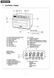
NE-3280 / NE-2180 / NE-2180C 1 CONTROL PANEL 4
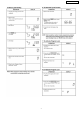
NE-3280 / NE-2180 / NE-2180C 2 OPERATION PROCEDURE 5
NE-3280 / NE-2180 / NE-2180C 6
NE-3280 / NE-2180 / NE-2180C 7
NE-3280 / NE-2180 / NE-2180C 8
NE-3280 / NE-2180 / NE-2180C 3 SCHEMATIC DIAGRAM NE-3280 (USA) 9
NE-3280 / NE-2180 / NE-2180C 4 WIRING DIAGRAM NE-3280 (USA) NOTE: When replacing, check the lead wire colour as shown.
NE-3280 / NE-2180 / NE-2180C 5 SCHEMATIC DIAGRAM NE-2180C (CANADA) 11
NE-3280 / NE-2180 / NE-2180C 6 WIRING DIAGRAM NE-2180C (CANADA) NOTE: When replacing, check the lead wire colour as shown.
NE-3280 / NE-2180 / NE-2180C 7 SCHEMATIC DIAGRAM NE-2180 (USA) 13
NE-3280 / NE-2180 / NE-2180C 8 WIRING DIAGRAM NE-2180 (USA) NOTE: When replacing, check the lead wire colour as shown.
NE-3280 / NE-2180 / NE-2180C 9 DESCRIPTION OF OPERATING SEQUENCE Variable power cooking control shown in table. The coil of power relays are energized intermittently by the digital programmer circuit, when the oven is set at any power selection except for High power position. The digital programmer circuit controls the ON-OFF time of the power relays contacts in order to vary the output power of the microwave oven.
NE-3280 / NE-2180 / NE-2180C 10 CAUTIONS TO BE OBSERVED WHEN TROUBLESHOOTING Unlike many other appliances, the microwave oven is highvoltage, high-current equipment. Though it is free from danger in ordinary use, extreme care should be taken during repair. 10.3. When parts must be replaced, remove the power plug from the outlet. CAUTION Servicemen should remove their watches whenever working close to or replacing the magnetron. 10.4. When the 15 Amp. (NE2180/NE-2180C) or 20 Amp.
NE-3280 / NE-2180 / NE-2180C 2. Make sure that all electrical connections are tight before inserting the plug into the wall outlet. 10.6. Confirm after repair 1. After repair or replacement of parts, make sure that the screws of the oven, etc. are neither loose nor missing. 3. Check for microwave energy leakage. (Refer to procedure for measuring microwave energy leakage.
NE-3280 / NE-2180 / NE-2180C NOTE: Do not use a soldering iron or desoldering tool of more than 30 watts on DPC contacts. 2. With all the terminal pins cleaned and separated from DPC contacts, remove the defective transformer/power relays and install new transformer/power relays making sure all terminal pins are inserted completely. Resolder all terminal contacts carefully. 11.4. Disassembly of door assembly 1. Detach the door spring ends from right and left door arms. 2.
NE-3280 / NE-2180 / NE-2180C 2. Remove 2 screws holding upper antenna assy by inserting screwdriver through the opening on the antenna as shown in figure. 11.6. Lower antenna (Right and Left) Lower antenna (Right and Left) 1. To remove the floor shelf, insert a screwdriver through the openings on the right and left sides of the oven cavity and carefully lift the floor shelf as shown in figure. 2.
NE-3280 / NE-2180 / NE-2180C Upper Antenna Motor Lower Antenna Motor PART NO.: ANE61446030AP (RATED: 120V) PART NO.: A6144-3280 (RATED: 120V) 11.9. Program, Beep and Program Lock switches board. (P.C.Board F assy) 1. Remove air filters. 2. Place the unit on its left side carefully. 3. Peel off panel B. 4. Remove 1 screw holding cover. (Figure) 5. Remove 2 screws holding switch assy. 6. Remove connector and remove 2 screws holding switch board. 11.10. Voltage selection (208V→ →230V) 1.
NE-3280 / NE-2180 / NE-2180C 12 COMPONENT TEST PROCEDURE check continuity. CAUTION 1. High voltage is present at the high voltage terminal of the high voltage transformer during any cook cycle. 2. Normal (cold) resistance readings should be as follows: · Secondary winding Approx. 40Ω — 100Ω 2. It is neither necessary nor advisable to attempt measurement of the high voltage. · Filament winding Approx. 0Ω 3.
NE-3280 / NE-2180 / NE-2180C 12.7. Membrane key board (Membrane switch assembly) Check continuity between switch terminals, by tapping an appropriate pad on the key board. The contacts assignment of the respective pads on the key board is as shown in digital programmer circuit. 12.8. Protector diode 1. Isolate the protector diode assembly from the circuit by disconnecting its leads. 2. With the ohmmeter set on the highest resistance scale, measure the resistance across the protector diode terminals.
NE-3280 / NE-2180 / NE-2180C 13 MEASUREMENTS AND ADJUSTMENTS 13.1. Adjustment of the secondary interlock switch (SAFETY SWITCH B) (Right and Left side) 1. Switch operation When the door is slightly opened, the secondary interlock switch opens the main circuit. The movement of the door from the closed position to the operation position (shown as liter) of the switch when it opens the main circuit, must maintain within following tolerances.
NE-3280 / NE-2180 / NE-2180C with the thermometer and note the temperature. (Record as T2) 13.3. Adjustment of the primary interlock switch (SAFETY SWITCH A) (Right and Left side) The normal temperature rise (T2 — T1) at High power position for each models is as shown in following table. Model NE-3280 NE-2180 NE-2180C 1. Switch operation When the door is slightly opened, the contacts of primary interlock switch opened to give digital programmer circuit the information that the door is opend.
NE-3280 / NE-2180 / NE-2180C · Glass thermometer 212°F or 100°C 14.4. At least once a year, have the radiation monitor checked for calibration by its manufacturer. · 600cc glass beaker 14.2. Procedure for measuring radiation leakage Note before measuring 1. Do not exceed meter full scale deflection Leakage monitor should initially be set to the highest scale. 2.
NE-3280 / NE-2180 / NE-2180C 15 TROUBLESHOOTING GUIDE CAUTION 1. Check grounding before checking for trouble. 2. Be careful of the high voltage circuit. 3. Discharge high voltage capacitor. 4. When checking the continuity of the switches or the high voltage transformer, disconnect one lead wire from these parts and then check continuity with the AC plug removed. To do otherwise may result in a false reading or damage to your meter.
NE-3280 / NE-2180 / NE-2180C DISPLAY F89 CONDITIONS Shorted contacts of RY9 POSSIBLE CAUSE 1. Relay failure RY-9 (D) TIMING OF FAILURE INDICATION It is appeared when failure occured. 2. Digital programmer circuit failure [TROUBLE] Oven does not operate at all or oven does not start cooking. NE-2180, NE-2180C DISPLAY F33 F34 CONDITIONS Open temperature sensor (exhaust) Short temperature sensor (exhaust) F44 POSSIBLE CAUSE 1. Temperature sensor failure 2. Digital programmer circuit failure 3.
NE-3280 / NE-2180 / NE-2180C 16 EXPODED VIEW AND PARTS LIST 28
NE-3280 / NE-2180 / NE-2180C 29
NE-3280 / NE-2180 / NE-2180C 17 PARTS LIST NOTE When ordering replacement part(s), please use part number(s) shown in this parts list. Do not use description of the part. Importan safety notice: Components identified by mark have special characteristics important for safety. When replacing any of these components, use only manufacturere’s specified parts. Ref. No. Part No.
NE-3280 / NE-2180 / NE-2180C Ref. No. Part No.
NE-3280 / NE-2180 / NE-2180C Ref. No. Part No.
NE-3280 / NE-2180 / NE-2180C Ref. No. Part No.
NE-3280 / NE-2180 / NE-2180C Ref. No. Part No.
NE-3280 / NE-2180 / NE-2180C Ref. No. Part No. D12 XYEANE4+C16T D12 XYEANE4+C16T D13 A30853030GP D14 ANE0245X00AP D15 ANE01728U0CP Part Name & Description SCREW SCREW DOOR C DHHS LABEL CAUTION LABEL Pcs/Set 4 4 1 1 1 Remarks 4X16 4X16 NE-3280,NE2180 NOTE: Please order DHHS label together. 19 ESCUTCHEON BASE ASSEMBLE Ref. No. Part No.
NE-3280 / NE-2180 / NE-2180C 20 PACKING AND ACCESSORIES Ref. No. Part No.
NE-3280 / NE-2180 / NE-2180C 21 WIRING MATERIAL 37
NE-3280 / NE-2180 / NE-2180C Ref. No. Part No.
NE-3280 / NE-2180 / NE-2180C Ref. No. Part No. W3 A03623560GP W4 A03633560GP W5 A604Q3570AP W6 A03653560GP W7 A03693560GP W8 A03703560GP W9 A03723A60BP W10 A604Q3590AP W11 A50966520UP W12 A606W3560GP W13 A606V3580GP W14 A606V3560GP Ref. No. Part No.
NE-3280 / NE-2180 / NE-2180C Ref. No. Part No.
NE-3280 / NE-2180 / NE-2180C 41
NE-3280 / NE-2180 / NE-2180C 23 DIGITAL PROGRAMMER CIRCUIT PARTS LIST 42
NE-3280 / NE-2180 / NE-2180C Ref. No. C10,12,13,15,16,17 ,19,22,26,29 C11 C14 C18 C20,C21,C23,C24,C2 7,C28 Part No. AECF50F104Z Description CERAMIC CAPACITOR Pcs/set 10 0.1MF/50V ECA1HM221B ECEA1CKA100B ECEA1HKA2R2B ECBT1E103ZF5 ELECTROLYTIC CAPACITOR,AL ELECTROLYTIC CAPACITOR,AL ELECTROLYTIC CAPACITOR,AL CERAMIC CAPACITOR 1 1 1 6 220MF/50V 10MF/16V 2.2MF/50V 0.