
user manual


CAUTION
1. High voltage is present at the high voltage terminal of the high
voltage transformer during any cook cycle.
2. It is neither necessary nor advisable to attempt measurement of
the high voltage.
3. Before touching any oven components, or wiring, always unplug
the oven from its power source and discharge the high voltage
capacitor.
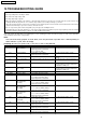
12.1. Primary Interlock Switch
(SAFETY SWITCH A),
Secondary Interlock Switch
(SAFETY SWITCH B) and
Power Relay
1. Unplug the power cable.
2. Unplug lead wire connectors to Power Relay (RY2-16) and
verify continuity of the power relay terminals.
3. Unplug lead wire connectors to Primary Interlock Switch
and Secondary Interlock Switch.
4. Test the continuity of switches with the door in both open
and closed positions with ohm meter (low scale). Normal
continuity readings should be as follows.
Door Opened Door Closed
Primary Interelock
Switch
Ω (open)
0Ω (close)
Secondary Interlock
Switch
Ω (open)
0Ω (close)
Power Relays
Ω (open)
0Ω (close)
12.2. Short/Monitor Switch (Both
Right and Left)
Door Opened Door Closed
NO Terminals
Ω (open)
0Ω (close)
NC Terminals 0Ω (close)
Ω (open)
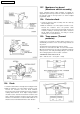
12.3. High voltage transformer
1. Remove connections from the transformer terminals and
check continuity.
2. Normal (cold) resistance readings should be as follows:
·
Secondary winding Approx. 40Ω — 100Ω
·
Filament winding Approx. 0Ω
·
Primary winding Approx. 0Ω —3Ω
12.4. High voltage capacitor
1. Check continuity of capacitor with meter on highest OHM
scale.
2. A normal capacitor will show continuity for a short time, and
then indicate 9MΩ once the capacitor is charged.
3. A shorted capacitor will show continuous continuity.
4. An open capacitor will show constant 9MΩ.
5. Resistance between each terminal and chassis should be
infinite.
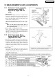
12.5. Magnetron
Continuity checks can only indicate an open filament or a
shorted magnetron. To diagnose for an openfilament or
shorted magnetron.
1. Isolate magnetron from the circuit by disconnecting the
leads.
2. A continuity check across magnetron filament terminals
should indicate one ohm or less.
3. A continuity check between each filament terminal and
magnetron case should read open.
12 COMPONENT TEST PROCEDURE
21
NE-3280 / NE-2180 / NE-2180C