
Two-Way Radio User Manual


2-67
1
Before Using the Products
2
Preparation
3
Connection
4
Setup
5
Adjustment
6
When in Trouble
7
Supplement
Caution
This driver (A to G-frame) is equipped with a dynamic brake for emergency stop.
Pay a special attention to the followings.
The H-frame driver does not incorporate the dynamic brake.
1. Dynamic brake is only for emergency stop.
Do not start/stop the motor by turning on/off the Servo-ON signal (SRV-ON).
Otherwise it may damage the dynamic brake circuit of the driver.
The Motor becomes a dynamo when driven externally and short circuit cur-
UHQWRFFXUUHGZKLOHG\QDPLFEUDNHLVDFWLYDWHGPD\FDXVHVPRNLQJRUÀUH
2.
Dynamic brake is a short-duration rating, and designed for only emergency stop. Allow ap-
prox. 10 minutes pause when the dynamic brake is activated during high-speed running.
(F-frame(200V), G-frame(200V/400V) built-in dynamic brake resistor is capable of
handling up to 3 continuous halts at the rated revolutions with max. permissible inertia.
When overheated under more critical operating conditions, the brake will blow out and
should be replaced with a new one.)
<RXFDQDFWLYDWHWKHG\QDPLFEUDNHLQWKHIROORZLQJFDVHV
1) When the main power is turned off
2) At Servo-OFF
3) When one of the protective function is activated.
4) When over-travel inhibit input (NOT, POT) of connector X4 is activated
In the above cases from 1) to 4), you can select either activation of the dynamic brake
or making the motor free-run during deceleration or after the stop, with parameter.
Note that when the control power is off, for A to F-frame driver, the dynamic brake will
be kept actived, and for G and H-frame driver, the dynamic brake will be kept released.
,IWKHEXLOWLQG\QDPLFEUDNHUHVLVWRURIWKH*IUDPHGULYHULVLQVXIÀFLHQWH[WHU-
nal dynamic brake resistors can be connected.
)RUWKH+IUDPHGULYHUH[WHUQDOG\QDPLFEUDNHUHVLVWRUVFDQEHFRQQHFWHG
Connections of the external dynamic brake resistors are the same as those of
the G-frame driver. (The DB3 and DB4 terminals are not provided.)
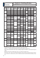
8VHWKHIROORZLQJUHVLVWRUVDVWKHH[WHUQDOG\QDPLFEUDNHUHVLVWRUV7REHSUH-
pared by user)
Driver
Resistance specifications per piece
Quantity of use
Frame Voltage Resistance Electric power
G, H 200V ї 400W 3 pcs.
G, H 400V ї 400W 3 pcs.
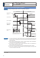
Dynamic Brake Characteristics (e.g. Motor MDME 15kW 200V)
0 500 1000 1500 2000
Motor speed (r/min)
Brake torque (N・m)
Resistor 1.2ї
Resistor 2.4ї
0
10
20
30
40
50
60
70
80
2
Preparation
12. Dynamic Brake
Outline
Related page
3´,QSXWVDQGRXWSXWVRQFRQQHFWRU;µ
3´'HWDLOVRI3DUDPHWHUµ
3´3URWHFWLYH)XQFWLRQµ