
Two-Way Radio User Manual


7-30
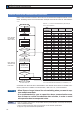
Interface of Communication Connector
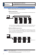
&RQQHFWLRQWRWKHKRVWZLWK56
&RQQHFWLRQWRWKHKRVWZLWK56
4. Communication
Specifications
* No connection to X5 when no
external scale is used.
Host controller
RS232
interface
SN751701
or equivalent
Motor
Relay
connector
Positioning
controller
TXD
RXD
GND
4
3
1
Servo driver
RXD
TXD
GND
6
RS485+
5
8
7
RS485ï
RS485+
RS485ï
X2
RS485 can be
connecter to either
terminal pair.
X4
X6
Detection
head
External scale unit
Relay
connector
X5
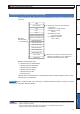
SN751701
or equivalent
Motor
Relay
connector
4
3
1
RXD
TXD
GND
6
RS485+
5
RS485ï
8
RS485+
7
RS485ï
X2
X4
X6
Detection
head
External scale unit
Relay
connector
X5
RS485 can be
connecter to either
terminal pair.
When longer wirings
are used and/or drivers
are connected to
different power
sources, interconnect
GND terminals of these
drivers to prevent
potential generation.
* No connection to X5 when no
external scale is used.
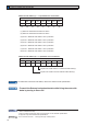
Motor
Relay
connector
X4
X6
Detection
head
External scale unit
Relay
connector
X5
RS485
interface
ADM485
or equivalent
RS485+
RS485–
GND
8
7
Servo driver
X2
RS485+
6
5
1
RS485–
GND
RS485+
RS485–
Host controller
Positioning
controller
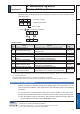
Communication Method
RS232 56
Full duplex, asynchronous Half duplex, asynchronous
Communication baud rate
2400, 4800, 9600, 19200, 38400, 57600, 115200bps 2400, 4800, 9600, 19200, 38400, 57600, 115200bps
Data 8 bit 8 bit
Parity none none
Start bit 1 bit 1 bit
Stop bit 1 bit 1 bit
Set up the RS232 communication baud rate with Pr5.29, and RS485 communication baud
rate with Pr5.30. The change of these parameters will be validated after the control power
entry. For details, refer to the following list of parameters related to communication.
Note
2QO\IRUSRVLWLRQFRQWUROW\SHLVQRWSURYLGHGZLWK;&RPPXQLFDWLRQFRQQHFWRUDQG;&RQ-
nector for External Scale).
2QO\IRUSRVLWLRQFRQWUROW\SHGRHVQRWVXSSRUWWKHELWDEVROXWHVSHFLÀFDWLRQ
,WVXSSRUWVRQO\ELWLQFUHPHQWDOVSHFLÀFDWLRQ