Matrix Switcher Operating Instructions Model No. WJ-SX150 OPERATE OPERAT E LED WIL IF COO LING FAN L BLINK MALFUN CTIONS Matrix Sw itcher WJ -SX 150 Before attempting to connect or operate this product, please read these instructions carefully and save this manual for future use.
ENGLISH VERSION Caution: Before attempting to connect or operate this product, please read the label on the bottom. CAUTION RISK OF ELECTRIC SHOCK DO NOT OPEN CAUTION: TO REDUCE THE RISK OF ELECTRIC SHOCK, DO NOT REMOVE COVER (OR BACK). NO USER-SERVICEABLE PARTS INSIDE. REFER SERVICING TO QUALIFIED SERVICE PERSONNEL.
IMPORTANT SAFETY INSTRUCTIONS 1) Read these instructions. 2) Keep these instructions. 3) Heed all warnings. 4) Follow all instructions. 5) Do not use this apparatus near water. 6) Clean only with dry cloth. 7) Do not block any ventilation openings. Install in accordance with the manufacturer's instructions. 8) Do not use near any heat sources such as radiators, heat registers, stoves, or other apparatus (including amplifiers) that produce heat.
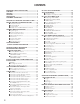
CONTENTS IIMPORTANT SAFETY INSTRUCTIONS ......................... 3 CONTENTS ....................................................................... 4 PREFACE .......................................................................... 6 FEATURES ....................................................................... 6 PRECAUTIONS ................................................................. 7 DOCUMENT CONVENTION ............................................. 7 FEATURES OF THE MATRIX SWITCHER SYSTEM ......
CAMERA FUNCTION CONTROL ....................................94 ■ Camera Setup ........................................................94 ■ Camera Function (Shortcut Function) ....................94 ■ Changing to Black and White Images ...................95 ■ Patrol Learn and Play ............................................95 ■ Camera Panning Function .....................................96 CAMERA SITE ACCESSORIES CONTROL ...................97 ■ Receiver Control .............................................
PREFACE Matrix Switcher WJ-SX150 is designed for a surveillance control system, which is composed of 16 cameras, 4 monitors and 4 system controllers. System controllers are used to operate the surveillance control system. In combination with Digital Disk Recorder WJ-HD500 Series, *WJ-HD100 Series or a time-lapse VCR, a surveillance system can be established in a local area. * To use WJ-HD100 Series or a time-lapse VCR, you need to install Multiplexer Board WJ-SXB151 inside the matrix switcher.
PRECAUTIONS • Refer all work related to the installation of this product to qualified service personnel or system installers. • Do not block the ventilation opening or slots on the cover. To prevent the appliance from overheating, place it at least 5 cm (2 inches) away from the wall. • Do not drop metallic parts through slots. This could permanently damage the appliance. Turn the power off immediately and contact qualified service personnel for service. • Do not attempt to disassemble the appliance.
FEATURES OF THE MATRIX SWITCHER SYSTEM 9
MATRIX SWITCHER SYSTEM DESCRIPTIONS Matrix Switcher System WJ-SX150 is a surveillance control system, which is composed of cameras, recorders, and this unit (the matrix switcher). This system has various functions for surveillance control. The following are the descriptions about the functions.
● Sequence Mode Monitor 1 Dwell time: 2 sec. Step 1 Monitor 1 Dwell time: 2 sec. Step 2 s Monitor 1 Dwell time: 2 sec. Step 3 s s More than one camera's images are sequentially displayed for a fixed time. The illustration shows an example of the sequential display of images through Camera 2, 4, and 6 on Monitor 1. Before use, the parameters* of the sequence need to be configured and uploaded to the unit. * Example: Camera selection, monitor selection, and dwell time (the time to display each image).
Signal type Function Control signal Controls camera functions (pan/tilt, zooming, focusing, lens iris, preset position) and camera site accessories. Status signal Shows camera status. Timing pulse (VD2) This signal is supplied to the unit to each camera. Each figure shows the picture status with or without the timing pulse. VD2 OFF s VD2 ON s s s ■ Example of a SYSTEM with Basic Functions The illustration in the next page shows the surveillance system in a parking lot as an example.
Monitor 2 displays Camera 6's image consistently in the spot mode. Operators will observe the parking lot by looking at these images on a monitor in a management office. Receiver Camera 1 Camera 5 Camera 4 Aux 1 Preset position 1 Preset position 2 Sensor Aux 2 Camera 6 Recorder Matrix switcher t t t Alarm Alarm 3 OPERATE OPERATE LED WILL BLINK IF COOLING FAN MALFUNCTIONS Matrix Switcher WJ-SX Sequence mode s Monitor 1 s s s Gate opens.
TERMINAL MODE DESCRIPTIONS ation conflict. In the terminal mode, each external device (such as a camera, monitor, system controller, or a recorder, etc.) has the name and number (Camera 1, etc.). When you control a device, you are to select the device number and execute the selection. For example, before controlling Camera 1, you will press the numeric button 1, and then press the CAM (SET) button. Each operator has a level and priority.
■ Monitor-related Functions The following functions related to monitors are configurable. 08/21/2001 6:50:08 PM Clock STILL* (Still spot** or still multiscreen display is activated.) * ”STILL” appears when a Multiplexer board is installed inside the matrix switcher. **Available only during playback Note: When pressing the associated numeric button (1 to 5) while holding down the OSD button, information is turned on or off.
In each step, the desired preset position of a camera can be called and displayed. Tour sequences are configurable in SETUP MENU and WJSX150 Administrator Console. Group Sequence Group sequence is a function to display up to 4 tour sequences in a group on up to 4 monitors. More than one sequences can be activated at one time by registering each tour sequence in a group. Up to 4 tour sequences can be registered in a group. Focus This setting adjusts the lens focus.
● External Equipment Control When the camera is connected via a receiver, the external equipment connected to the receiver can be controlled. ● Controllable Camera-related Functions The control is conducted while watching the camera images on the monitor. • Changing to black and white pictures • Camera function (Shortcut function) Note: The specified cameras can control each function. Confirm the functions of the connected cameras and external devices.
● Sequence Mode ● Video Loss History Table In the sequence mode, the unit displays the initial alarm image on the monitor until the dwell time ends, even when another alarm input is accepted. When the dwell time ends, the unit automatically replaces the alarm image with the next one. While the unit's power is ON, the video signal loss from a camera or a recorder can occur by cable disconnection, etc.
■ System Status Table ■ Extended Functions The current system status can be identified. The continuous display becomes possible by the OSD setting. If a recorder is connected to the matrix switcher, the following will be available. ● Recorder Connection SYSTEM STATUS MON 1 2 3 4 CAM 01 02 04 16 MODE T01 SPOT ALARM CAM KB K1 K2 K4 PC OPE 1 2 4 30 PRI 16 2 1 1 The time-lapse recording and playback of all the camera images connected to the unit are possible.
●Multiplexer Board Function To use WJ-HD 100 Series or a time-lapse VCR as a recorder, you need to install a multiplexer board inside the matrix switcher. With the multiplexer board installation, the following will be available. • Multiscreen display More than one camera images can be displayed in 4, 9, and 16 multiscreens. The sequence output is also available. As the sequence output, the following are configurable in WJ-SX150 Administrator Console. • The images are switched within 4 multiscreens.
• Motion Detector When the multiplexer board detects motions in the image, the multiplexer board sends an alarm signal to the unit. Then, the unit will send the alarm signal to the connected devices. The areas can be divided in four segments, and the detection is conducted in each segment. For example, this function can be applied to a time-lapse recording, which responds to the break-in at night. Notes: • The motion detector area needs to be configured in SETUP MENU in advance.
NOTIFICATION ABOUT PS·DATA CONTROLLER OPERATION In the factory default setting, you can control the unit, if you connect a PS·Data system controller to the DATA 4 port. For example, if you connect a PS·Data unit supporting network connections (refer to p. 43), remote-control of the unit and the PS·Data units will be available with a system controller or PC. When you use a PS·Data system controller, take notice the following: • The administer authorization and log-in/log-out procedure differs from the unit.
DETAILED PRODUCT DESCRIPTION 23
MAJOR OPERATING CONTROLS AND THEIR FUNCTIONS ■ WJ-SX150 Matrix Switcher ● Front View q OPERATE OPERATE LED WILL BLINK IF COOLING FAN MALFUNCTIONS Matrix Switcher WJ-SX w e RESET r UNIT 78 456 q Operation indicator (OPERATE) Lights up when the power of the unit is turned on. Note: The indicator will blink to indicate rising temperature in the matrix switcher. When the indicator blinks, turn the power off and refer servicing to qualified service personnel.
● Rear View u o !0 !1 i ALARM DATA HDR DATA 4 SERIAL DATA 3 DATA 2 DATA 1 TERM OFF ON PS•DATA 16 y IN t OUT 15 14 13 12 11 10 !2 !3!4 !5 !6 EXT IN (PLAY IN) CAMERA SW IN RS485(CAMERA) LINE 2 SELECT 4 RS485(CAMERA) 9 8 7 6 5 EXT OUT (REC OUT) 4 3 4 MONITOR OUT 3 2 !7 1 !8 SIGNAL GND POWER 2 1 AC IN 16 15 14 13 12 11 10 9 8 7 6 5 4 3 2 1 CAMERA !9 t Camera Output connectors (CAMERA OUT 1–16) The video signal connected to the CAMERA IN connector is supp
■ WV-CU360C System Controller (TERMINAL MODE) A template, on which “For Matrix Switcher (WJ-SX150)” is written, is provided with System Controller WV-CU360C. When using the template, place it on the surface of the controller. In these operating instructions, this template's illustrations are used for descriptions.
#0 Focus buttons (FOCUS NEAR/FAR) Adjust the lens focus of cameras equipped with the specified lens. Press the NEAR and FAR buttons simultaneously. The lens focus is adjusted automatically, if the specified auto focus camera is equipped. #1 Zoom buttons (ZOOM WIDE/TELE) Press these buttons to zoom the lenses equipped with the specified cameras. Press the WIDE and TELE buttons simultaneously during the recorder mode. The recording is started.
$4 Next button (NEXT) Moves a tour sequence one step forward from the step previously paused on the active monitor. Also selects a camera. If the active monitor is in the spot mode, press NEXT while holding down the CAM (SET) button, to replace the currently selected camera with the next higher-numbered camera. During the recorder mode, this button moves the playback image one step forward.
■ WV-CU360CJ System Controller (TERMINAL MODE) A template, on which “For Matrix Switcher (WJ-SX150)” is written, is provided with System Controller WV-CU360CJ. When using the template, place it on the surface of the controller.
^2 Joystick Use this joystick to manually operate cameras, camera site accessories and a recorder, or to move the cursor in SETUP MENU on the active monitor screen. }: Up {: Down [: Left, rewind*, backward field advance* ]: Right, fast-forward*, forward field advance* *Available after pressing the RECORDER button while connecting to a recorder. ^3 Top button Pressing this button will automatically set the lens focus of a specified camera.
SUSPEND: To suspend an activated alarm, press this button while holding down the SHIFT button. "ALM SUSPENDED" will appear on the monitor. To cancel the suspension, press this button while holding down the SHIFT button again. &5 Function 1 button (F1/CAM SETUP) Press this button while holding down the SHIFT button to open the camera's SETUP MENU on the active monitor. The function as the F1 button is reserved for future use.
● Rear View *8 78 CONTROLLER No. MODE DATA (3 *8 Controller Number switch (CONTROLLER No.) Selects a number for the system controller for identification in a system. Normally, set the switch to number 1. 456 78 23 901 *9 Mode Selection switches (MODE) The operation mode of the system controller is selected with these switches. When you use a terminal-mode system controller, set the switches to the positions shown in the figure.
INSTALLATIONS AND SYSTEM CONNECTIONS 33
INSTALLATIONS WARNING The installations described in the figures should be made by qualified service personnel or system installers. ■ Mounting into the Rack The matrix switcher can be mounted into the rack as described. 1. Remove the four rubber feet by unwinding the four screws on the bottom of the matrix switcher. Notes: • An optional cooling fan attached inside the unit is subject to wear. It needs to be replaced periodically. Keep the temperature in the rack below 45 °C (113 °F) at any time.
SYSTEM CONNECTION EXAMPLES ■ Basic System Connection This is an example of basic system connection.
Notes: • Before connecting a terminal-mode system controller to the DATA 4 port, configure the system through SETUP MENU or WJ-SX150 Administrator Console. • If an optional network board is installed inside the recorder and you are to control it from LAN (local area network) or the Internet, refer to a service manual procurable in your area.
CONNECTIONS ■ Connection with the Camera Sites Connect the data-multiplex type cameras (or camera site equipment) to the CAMERA IN connectors 1 to 16 on the matrix switcher's rear panel. Notes: • Make sure that the cable length is less than 900 m (3 000 ft) between the camera site and the unit when using RG-59/U, BELDEN 9259 or equivalent cables. • If you use locally procuring cables, it is important to use only a data-grade cable, which is suitable for RS-485 communication (shielded 2-wire twisted cable).
■ Connections for RS-485 Type Camera (A) (B) GND There are two options to connect the camera with the matrix switcher, depending on the distance between them. One is "Home Run" wiring and the other is daisy chain wiring. "Home Run" wiring has the transmission stability with less transmission loss, and daisy chain wiring has connection flexibility with less data ports occupied.
The switch on a daisychain-connected unit other than the extremities must be set to OFF. (A) (B) GND OFF ■ Connection with the Monitors The switch on the end unit should be set to ON. (A) (B) GND ON OFF Connect the monitors to the MONITOR OUT connectors at the unit's rear panel with the coaxial cable. The connectors MONITOR OUT 1 to 4 are associated to ON Martix Switcher 3 WV-CPR450 and others (For the termination switch positions, refer to the operating instruction of the corresponding unit.
■ Connection with the System Controllers ■ Connection with the Alarm Sensors Connect the system controller to the DATA 1 to 4 port at the unit's rear panel with the modular cable. Connect the sensor switches to the unit's alarm port, as shown in the example. Recover Input Alarm Sensor 1 13 DATA HDR DATA 4 DATA 3 DATA 2 DATA 1 LINE 2 SELECT 4 TERM OFF ON PS•DATA 1 RS485(CAMERA) ALARM RS485(CAMERA) 25 WJ-SX150 Pin No.
■ Connection with the Alarm Output Pins #10, 11, 23 and 24 (open collector) turns to 0 V while the alarm is activated. These terminals can drive external warning devices such as a buzzer or lamp of up to 100 mA, 16 V DC. If the rating exceeds 100 mA, 16 V DC use a relay as shown in Example 2. Alarm signals are output from the terminals until the reset.
Notes: • You cannot record the camera images in maximum recording rate through this connection. Refer to the next connection example in this page. • The recorder will not operate if its unit address is set to other than 1. ● To Record the Camera Images in Maximum Recording Rate The following is the description of the connection between a recorder and this unit for the maximum-rate recording. 1. Set the unit address of the recorder to 1. Then, set the recorder’s CAMERA GENLOCK to ON in its SETUP MENU.
● To Control a Recorder via the Network Monitor The following is the description of the connection between a recorder and this unit to control the recorder via the network. 1. Set the recorder's unit address to a number 5 or larger . (Refer to the recorder's operating instructions.) 2. Connect the unit’s CAM OUT 1 to 16 connectors to the recorder’s VIDEO IN 1 to 16 connectors with a coaxial cable.
■ Connection with Digital Disk Recorder WJ-HD100 Series 1. To record the camera images with Digital Disk Recorder WJ-HD100 Series, install an optional Multiplexer board in the matrix switcher. 2. Connect the matrix switcher’s EXT OUT (REC OUT) to the digital disk recorder’s VIDEO IN with a coaxial cable. 3. Connect the matrix switcher’s EXT IN (PLAY IN) to the digital disk recorder’s MONITOR OUT (PLAY) with a coaxial cable. 4.
■ Connection with the Time-lapse VCR (Panasonic Models) 1. Configure the parameters of the multiplexer functions in the Multiplexer Mode (refer to p. 82) window of WJ-SX150 Administrator Console. Note: When VCR is selected in 610 RECORDER CONTROL in SETUP MENU (refer to p. 60), parameter configuration in the Multiplexer Mode window is unavailable. 2. Select VCR for 610 RECORDER CONTROL in SETUP MENU. (Refer to p. 60.) 3. Conform the communication speed (COMM.
■ Cable Specifications AG6730, AG6740 RT850 WJ-SX150 T/L VCR WJ-SX150 1 2 3 4 5 6 7 8 1 2 3 4 5 6 7 8 9 1 2 3 4 5 6 7 8 9 20 22 Frame Frame RT850 1 2 3 4 5 6 7 8 9 Straight Cable Shield ■ Connection with the Time-lapse VCR (Non-Panasonic Models) 1. 2. 3. 4. To record the camera images through a time-lapse VCR, install an optional Multiplexer board in the matrix switcher. Select OFF for 610 RECORDER CONTROL in SETUP MENU.
■ Connection with the PC ■ Time Adjustment with an External Equipment 1. Conform the communication speed (SERIAL PORT SPEED) parameter in SETUP MENU to that of the PC. 2. Connect the matrix switcher's serial port to that of the PC with the 9-pin D-sub cable. D-sub9 or D-sub25 D-sub9 The specified external devices can output the time adjusting signal to the matrix switcher. This signal can adjust the time by up to ± 30 seconds every hour.
WJ-SX150 SETUP PROCEDURES 49
SETUP PROCEDURES ■ Setup Procedures This unit has two setting procedures. The one is SETUP MENU, which is the unit's on-screen display (OSD). The other is WJ-SX150 Administrator Console, which operates on the PC. Notes: • To use WJ-SX150 Administrator Console, you need to prepare a PC and a 9-pin D-sub cable.(Refer to p. 47.) • When changing the configuration of WJ-SX150 Administrator Console, configuration data getting and putting are necessary between the unit and PC to activate your configuration.
• It is also selectable whether to activate the recording and sequence/spot image monitoring when an alarm signal is input to the unit. Alarm recording without the sequence/spot image monitoring is also available. ● Operator Settings If you control this unit with a terminal-mode system controller, your operator information, controllable monitors and auto log-in/log-out will be registrable and configurable. • Operator registration: Up to 16 operators are available.
WJ-SX150 SETUP MENU (OSD) The WJ-SX150 SETUP MENU (SETUP MENU) enables function controls that are not available by direct operation. Note: Only one operator can enter SETUP MENU. 1. Confirm that the camera and peripherals are correctly and securely connected and that all components are turned on. Joystick to L(A): Moves the cursor to the left. Joystick to R (B): Moves the cursor to the right. PREV button: Selects the previous mode or parameter. NEXT button: Selects the next mode or parameter.
● How to Display To display this menu on the monitor, move the cursor to 100 TIME & DATE in SETUP MENU by moving the joystick to D or C. ● Parameters You can move the cursor to each parameter by moving the joystick to A or B. • Month Press the NEXT or PREV button to select the correct month. • Day Press the numeric buttons to enter it directly.
x.xx/x.xx WJ-SX150 SETUP MENU 100 TIME&DATE 200 D.S.T. 300 400 500 600 700 800 300 SEQUENCE TOUR NO. =1 Aug/21/2002 10:55 AM ON SEQUENCEO ALARMO CAMERA TITLEO RECORDERO SYSTEMO OPERATOR REGISTRATIONO 900 MULTIPLEXERO 1000 MUX CAMERA TITLEO STEP CAM 1 1 2 2 3 3 4 4 5 5 6 6 7 7 8 8 PRE DWELL -2S -2S -2S -2S -2S -2S -2S -2S STEP CAM 9 9 10 10 11 11 12 12 13 13 14 14 15 15 16 16 PRE DWELL -2S -2S -2S -2S -2S -2S -2S -2S 420 ALARM EVENT Outside the U. S.: · Aug/21/2002... 21/08/2002 · D. S. T....
• Year Press the numeric button to enter the correct year. ■ D. S. T. (Daylight Saving Time) WJ-SX150 SETUP MENU • TIME Press the numeric button to enter the correct time. • MINUTE Press the numeric button to enter the correct minute. • AM/PM Press the NEXT or PREV button to select the correct time. After the configuration, press the SETUP button while holding down the SHIFT button. The configuration will be updated when closing SETUP MENU.
TOUR NO: Press the NEXT or PREV button to select the tour number. Or press the numeric button(s) to enter a number. STEP: This stands for a tour sequence step. CAM: This stands for a camera number. CAM 0 to 16 is selectable. CAM 0 deactivates the sequence step. The factory default setting is assigned to each step in numerical order (STEP 1 = CAM 1, STEP 2 = CAM 2, STEP 3 = CAM 3, STEP = 4, CAM 4, STEP 5 = CAM 5…) PRE: This stands for a camera’s preset position number. 1 to 64 or "- -" is selectable.
• PRE: This item stands for the preset position number of a CAMnn. Enter the desired preset position number when selecting a combination camera. When selecting another type of camera, select --. • TOURnn (nn is a tour sequence number): Executes a tour sequence when an alarm input is accepted. The factory default setting is the same as the two illustrations above. Notes: • MODE and PRE cannot be selected by pressing the numeric buttons. Press the NEXT or PREV button for selection.
• MUX MOTION DET This menu appears only when the Multiplexer board is installed in the unit. This stands for that the unit’s motion detector is activated when a camera detects the brightness-level change and transmit an alarm signal. ON: The alarm-associated sequence/spot image is displayed on a monitor, and alarm recording will start (if a recorder is connected to the unit.) REC ONLY: Only alarm recording will start and monitors will keep displaying the current sequence/spot images.
Notes: • If you repeat Step 1 after setting 4 motion-detection areas, “NG” will blink at the center of the monitor for two seconds. • To reset a motion-detection area, move the “+” mark on the desired area. Then, press the CLEAR button. The area will be reset. • If an area overlaps another one, the newer area will be reset. ■ CAMERA TITLE 500 CAMERA TITLE CAM 1 2 3 4 5 6 7 8 1 of 2 TITLE 5. To configure the motion-detector areas of another camera channel, press the NEXT or PREV button.
• When moving the joystick to ▲ at the top of CAMERA TITLE 2 of 2, the monitor will display 1 of 2 (the previous page). • Original characters are configurable through WJSX150 Administrator Console, but they are not displayed correctly in SETUP MENU. They are displayed as ■. (Refer to p. 80 Edit Font window.) With the Multiplexer board VCR: Select this when a time-lapse VCR is connected to the unit. HD100: Select this when a WJ-HD100 Series recorder is connected to the unit.
CAM: This stands for the camera number. COMP: This stands for cable compensation. • DATA4/PSD PORT SELECT This stands for the operation mode: PS·Data or the terminal mode. Select the desired setting according to the cable length. S: Less than 400 m (1 300 ft) M: 400 m (1 300 ft) to 700 m (2 300 ft) L: 700 m (2 300 ft) to 900 m (3 000 ft) Refer to p. 37 for available cables. The factory default setting is S. VD2: To send the VD2 timing pulse with the camera output signal, select ON.
• CAMERA CLEANING ON: Activates the manual cleaning for the cameras. OFF: Deactivates the manual cleaning. When you set CAMERA CLEANING to ON and exit from the SETUP MENU, camera cleaning will start. The factory default setting is OFF. Notes: • When the camera cleaning is active, cleaning will begin from CAM 1 in numerical order. • Surveillance is impossible during the cleaning. • The cleaning cannot be stopped after it is started. • Refer to pp. 38 and 39 for details on RS-485 or PS·Data connections.
● Parameters Move the joystick to move the cursor. Press the NEXT or PREV button to select the desired parameters. • ALARM EXT: Select this to gen-lock the unit with the recorder when an alarm is input to the unit. 002,004 to 128 (field): Select one of these alarm recording rates if the asynchronous unit is connected to the unit. The factory default setting is EXT. • NORMAL EXT: Select this to gen-lock the unit during the normal operation.
WJ-SX150 ADMINISTRATOR CONSOLE ■ Description of WJ-SX150 Administrator Console WJ-SX150 Administrator Console is a utility software which can configure the system settings and control data of this surveillance system. WJ-SX150 Administrator Console can configure the following settings. ● RECORDER • Recorder (p. 66) ● MANAGEMENT • Put a File to SX150 (p. 67) • Get a Configuration Data from SX150 (p. 68) ● SETUP Sequence Settings • Tour Sequence (p. 68) • Group Sequence (p.
EXIT button Minimizing button →The selection will be memorized to WJ-SX150 Administrator Console while launching it. Note: To change the selection you have done in the "Startup Menu" window, restart the WJ-SX150 Administrator Console while holding down the SHIFT key on the PC keyboard. ● Startup/Termination 1. Select "Start" – "Program" – "Panasonic" – "WJ-SX150 Administrator Console x.xx*" or double-click the "WJSX150 Administrator Console x.x" icon on the desktop. * x.
RECORDER (Recorder Control): Recorder window (p. 66) MANAGEMENT (Put to SX150): Put a File to SX150 window (p. 67) (Get from SX150): Get a Configuration Data from SX150 window (p. 68) SEQUENCE (Tour Sequence): Tour Sequence window (p. 68) (Group Sequence): Group Sequence window (p. 69) SCHEDULE (Timer Event): Timer Event window (p. 70) (Camera Cleaning): Camera Cleaning window (p. 71) (Daylight Saving Time/Summer Time): Daylight Saving Time/Summer Time window (p.
Recorder Control: Click on the desired radio button to determine the recorder type. OFF: Select this when no recorder is connected to the unit. HD100: Select this when a WJ-HD100 Series recorder is connected to the unit. HD500: Select this when a WJ-HD500 Series recorder is connected to the unit. ■ Put a File to SX150 Pressing this button will start the putting of the configuration data from the PC to the unit. The factory default setting is HD500.
■ Get a Configuration Data from SX150 ■ Tour Sequence Pressing this button will start the getting of the configuration data from the unit to the PC. This window configures the parameters of tour sequences: the operating camera, dwell time*, preset position** in each step. Each sequence has up to 16 steps, and up to 16 sequences are configurable. The configuration of a tour sequence can be copied to another one.
(DELETE) button Deletes the configuration of all the steps of the selected tour sequence. (COPY) button Copies the configuration of all the steps of the selected tour sequence to the another tour. ■ Group Sequence This window configures the parameters of group sequences. Each group sequence has up to 4 tour sequences which are assigned to the monitors. (PASTE) button Pastes the cut or copied configuration to another tour sequence.
■ Timer Event This window configures the parameters of timer events: the schedule (daily, weekly or monthly) and action. Up to 30 events are configurable. tour sequence or spot mode is selectable. Spot Camera: Executes the spot mode according to the schedule in the Scheduled Mode group. When you have selected Spot Camera, select the number of monitor (Mon 1 to 4), camera (Cam 1 to 16) and preset position (Pre 1 to 64). (Save Exit) button Saves the configuration and closes the Timer Event window.
■ Camera Cleaning This window configures the parameters of camera cleaning function: the schedule (daily, weekly or monthly) and cameras to be cleaned. Notes: • When the camera cleaning is active, cleaning will begin from CAM 1 in numerical order. • Surveillance is impossible during the cleaning. • The cleaning cannot be stopped after it is started. ■ Daylight Saving Time/Summer Time This window configures the parameters of daylight saving time (summer time).
■ Alarm Mode This window configures the operation parameters when an alarm signal is input: an alarm mode, auto reset time and alarm input. (Save Exit) button: Saves the configuration and closes the Daylight Saving Time window. (Cancel Exit) button: Cancels the configuration and closes the Daylight Saving Time window. ● How to Display To display this window, click on the ton in the main window (p. 65). (Alarm Mode) but- ● Parameters • Alarm Mode Checking on the box of the desired alarm mode.
REC ONLY: Only an alarm recording will start and monitors will keep displaying the current sequence/spot images. Note: You cannot recover alarm-related operations from system controllers when REC ONLY is selected. OFF: An alarm input is accepted neither via the CAMERA IN connectors nor the RS-485 ports. ON: The alarm-associated sequence/spot image is displayed on a monitor, and alarm recording will start (if a recorder is connected to the unit.
• Alarm Reset Time Select the time to reset the alarm input. The selectable time: OFF (not resetting the alarm), 10, 20, 30, 40, 50, 60, 120 or 180 (seconds) The factory default setting is 30 sec. (Save Exit) button Saves the configuration and closes the Alarm Mode window. Notes: • If having selected a tour sequence for a monitor, another tour number or spot camera will not be available when selecting the monitor for another alarm event. That will result in an error.
■ Operator Registration This window configures the parameters of each operator: the ID, password, level, priority and camera access. Note: Before configuring this window, check on the restrict level of each operation in the Level Table window. • Camera Access Group This group configures the camera operation coverage of each operator. Click on each camera's checkboxes and determine the available operation.
■ Level Table ■ Monitor Selection This window configures the restrict level of each operation. The restrict level is classified in Level 1, 2, and 3. This window determines whether a system controller or PC can select a monitor. ● How to Display To display this window, click on the Selection) button in the main window (p. 65). (Monitor ● How to Display To display this window, click on the ton in the main window (p. 65).
■ Auto Login/Logout (Auto Log-in/Logout) This window configures the auto log-in/log-out parameter of each data port. An operator is selectable for auto log-in function. ■ Time & Date This window configures the unit's clock display pattern. The unit's clock time is also adjustable. This picture is the example for U. S. model. Out of the U. S., the display pattern is Date/Month/Year. ● How to Display The log-out time is selectable for auto log-out function.
● Clock ■ Cable Compensation/VD2/DATA This window configures the unit's clock. The pattern of the Time & Date box depends on the setting through the Time & Date window. This window configures the following parameters of each camera: the cable length for transmission loss compensation and whether to send the VD2 timing pulse or control data with the camera output signals. This picture is the example for U. S. model. • How to display To display this window, click on the the Time & Date window.
■ Camera Title ● Edit Camera Title This window configures the title for each camera. Up to 20 characters (camera title + alphanumeric characters) are available for the title. WJ-SX150 Administrator Console has the following built-in characters: ABCDEFGHIJKLMNOPQRSTUVWXYZabcdefghijklmnopqrs tuvwxyz0123456789!"#$%&'()*+,–./:; ,=/?•_ÄÜÖÆÑÂØäüöæñâøÁÇÉÌÒÙßàáâçèéêëìíîïòóôùúû In addition, symbols, special characters and original characters are editable in the bitmap font. 1.
● Edit Font Window The Window Soon after Opening Note: The new character has not been saved in the configuration data at this point. After closing the Edit Font window, be sure to return to the Camera Title window and click on the (Save Exit) button. • To Copy a Character 1. Click on the desired character in the User Font box. 2. Click on the Copy button. 3. Click on the blank in the User Font box to copy the character. 4. Click the Paste button.
■ Data Port This window configures the parameters of each data port (RS485, DATA 1 to 4 and DATA HDR port): the protocol, the baud rate (communication speed), and the connected cameras. Alarm Data: Select the desired time to accept an alarm input signal. OFF, 0, 1 or 5 sec is available. The factory default setting is 1 sec. Wait Time: Select the desired wait time to transmit an alarm output signal. OFF, 100msec, 200m sec, 400m sec or 1 sec is available. The factory default setting is OFF.
■ Multiplexer Mode ON: The drop-down menu becomes also active so that you can select the desired monitor among MON 1 to 4. For example, when you select MON 1, other operators, whose priority is lower than you, cannot view the monitor (secret view). OFF: Secret view function is unavailable. The factory default setting is OFF. ● How to Display Note: This window can be displayed only when “Yes” is selected in the Recorder window. (Refer to p. 66.
Alarm Group REC Mode: Select the desired setting by clicking on the radio button. EXT: Select this to gen-lock the unit during the alarm recording. INT: Select this if the asynchronous unit is connected to the unit. When it is activated, the drop-down menu becomes also active so that you can select the desired normal recording rate. 002, 004 to 128 (field) are selectable. (Save Exit) button Saves the configuration and closes the Multiplexer Mode window.
■ Select Setup Data File ● Multiplexer Title The setup file is selectable by pressing this button. For example, this function will be used when making a new setup file with the factory default setting or configuring an existing setup file. Refer to the operating instructions of Windows® for details of how to copy a data. ● How to Display To display this window, click on the in the main window (p. 65).
■ Account Manager This window configures the parameters of the operators who can control WJ-SX150 Administrator Console: the registration, edit and deletion of an operator. The window soon after opening (Add Account) button To register a new operator, click on this button. The Registration window will appear. (EDIT) button: To configure the operator information, click on this button. (DELETE) button To delete the operator selected in the Accounts group, click on this button.
■ Communication Port This window configures the PC's usable communication port number and its baud rate (communication speed). ● How to Display To display this window, click on the port) button in the main window (p. 65). (Communication ● Parameters • Parameter Group Com: Select the PC's communication port for the connection to the unit. Baud Rate: Select the desired baud rate (communication speed). 4800, 9600, 19200 or 38400 bps is selectable. The factory default setting is 38400 bps.
OPERATING PROCEDURES (TERMINAL MODE) 87
LOG-IN AND LOG-OUT Before starting the following procedures, all system components must be turned on. The following procedures are applicable when the system controller is connected to the unit. ■ Log-in This operation is skipped when the auto log-in is set to ON. (Refer to p. 89.) 1. Turn on the power switches of all system components. The OPERATE indicator will light up. 2. To turn on the power of the system controller, connect the AC adapter to the AC outlet.
■ Log-out ■ Auto Log-in This operation is skipped when the auto log-out is set to ON. This function is used when an operator leaves the controller or no longer requires access to the system. If the auto log-in is set to ON, any operator can login automatically. After the controller is turned on, "AUTO" appears on the LED display for approximately 2 seconds, then "READY" automatically appears. Auto log-in is configurable through WJ-SX150 Administrator Console. (Refer to p. 77 Auto Login/Logout.) 1.
MONITOR SELECTION AND CAMERA SELECTION After the log-in procedure, the following operations are available to control the system. The operation begins with selecting a monitor, then the selected camera appears the active monitor. ■ Monitor Selection 1. To select the desired monitor number (1 to 4), press the numeric button. 2. Press the MON (ESC) button to execute the selection.
■ Camera Selection 1. Select the desired monitor. (Refer to p. 90 Monitor Selection.) 2. Press the numeric buttons to select the desired camera number (1 to 16). 3. Press the CAM (SET) button. The selected camera's image will appear on the active monitor. The CAMERA indicator will light up and the selected camera number will appear on the LED display on the controller. Note: If you select a wrong number, press the CLEAR button to clear the input. 4.
CAMERA CONTROL Buttons and control for cameras or camera site accessories are located on the right side of the front panel of the system controller. Included are zoom control, focus control, iris control, preset and pan/tilt controls. Normally, combination cameras equipped with the specific feature or a WV-RC100 or WV-RC150 Receiver are required to utilize these functions. Note: Refer to the cameras' operating instructions whether to confirm that each function is available.
■ Program Preset Position ■ Call Preset Position 1. Select the desired monitor and camera. (Refer to p. 90 Monitor Selection and p. 91 Camera Selection.) 1. Select the desired monitor and camera. (Refer to p. 90 Monitor Selection and p. 91 Camera Selection.) 2. To move the camera to the position to be preset, move the joystick and press the lens control buttons. 2. To select the desired preset position number, press the numeric buttons. 3.
CAMERA FUNCTION CONTROL ■ Camera Function (Shortcut Function) ■ Camera Setup 1. Select the desired monitor and camera. (Refer to p. 90 Monitor Selection and p. 91 Camera Selection.) 2. Press the F1 button while holding down the SHIFT button. The CAM SETUP indicator on the controller will light up and the camera's SETUP MENU will appear on the active monitor. F1 ACK SUSPEND ALL RESET F2 GROUP SEQ TOUR SEQ REW/FF INDEX PREV NEXT 1. Select the desired monitor and camera. (Refer to p.
■ Changing to Black and White Images ■ Patrol Learn and Play This function gets the clear camera images on the monitor while shooting the objects under low light conditions. A routine of manual operations can be stored for a specific time and later reproduced repetitively. 1. Select the desired monitor and camera. (Refer to p. 90 Monitor Selection and p. 91 Camera Selection.) 1. Select the desired monitor and camera. (Refer to p. 90 Monitor Selection and p. 91 Camera Selection.) 2.
■ Camera Panning Function There are three panning modes available as follows: auto pan, sort mode and sequence mode. Refer to p. 16 Camera-related Functions for details on each mode. 1. Select the desired monitor and camera. (Refer to p. 90 Monitor Selection and p. 91 Camera Selection.) 2. Press the AUTO PAN button four times while holding down the SHIFT button. "PAN" will appear on the LED display of the controller as shown in the figure.
CAMERA SITE ACCESSORIES CONTROL ■ Receiver Control ● Auxiliary Control The following functions are available only when the receivers are included in the system and the specified camera housing is installed. ● Camera Housing Control Wiper Control 1. Select the desired monitor and camera. (Refer to p. 90 Monitor Selection and p. 91 Camera Selection.) 2. Press the CAM (SET) button while holding down the SHIFT button to turn on the housing wiper of the camera until buttons are released.
RUNNING SEQUENCE ■ Tour Sequence The following functions are available if a tour sequence has been previously configured through SETUP MENU or WJSX150 Administrator Console. Any tour sequence can be assigned to any monitors. 1. Select the desired monitor and camera. (Refer to p. 90 Monitor Selection and p. 91 Camera Selection.) 2. To select the desired tour sequence number, press the numeric buttons. 3. When you have selected a wrong number, press the CLEAR button to clear the numeric input. 4.
MONITOR DISPLAY CONTROL ■ On-screen Display (OSD) Control The procedure described below lets you determine the display parameters, such as camera title, clock and status, on and off on the active monitor screen. Before controlling each item, monitor selection is necessary. (Refer to p. 90 Monitor Selection.) ■ On-screen Display (OSD) Position Control The procedure described below lets you determine the display positions, such as camera title, clock and status, on the active monitor screen.
● Moving the Event Display MODE: Move the joystick while holding down the OSD, SHIFT and 3 buttons. (3) will move to the desired direction. ● Moving the Monitor Status* Move the joystick while holding down the OSD, SHIFT and 4 buttons. (4) will move to the desired direction. * Monitor number, controller number and monitor mode ● Moving All the Items Move the joystick while holding down the OSD, SHIFT and 5 buttons. (1), (2), (3), and (4) will move to the desired direction.
■ Alarm History Table ■ Video Loss History Table There are 100 alarm records stored in chronological order in 10 pages of tables. There are 100 video loss detection records stored in chronological order in 10 pages of table. 1. Select the desired monitor. (Refer to p. 90 Monitor Selection.) 1. Select the desired monitor. (Refer to p. 90 Monitor Selection.) 2. Press the button 7 while holding down the OSD button.
ALARM CONTROL ■ Alarm Mode ■ Operating during an Alarm Mode When alarm (sensor) is accepted, the matrix switcher's operation mode changes to the alarm mode. Then, the system operates as follows: • The camera image (alarm image) appears on the monitor. In the factory default setting, the alarm inputs 1 to 16 are associated with the same-numbered camera input connectors. All the video output signals are sent to Monitor 1.
■ Resetting the Alarm Inputs ● Alarm All Reset RESET There are two alarm reset functions: • Alarm reset (resetting the alarm inputs according to the input order) • Alarm all reset (resetting all the alarm inputs) ALL RESET TOUR SEQ T&D CAM ID EVENT STILL AUX1 OFF AUX1 ON NEXT MON STATUS ALL EL-ZOOM AUX2 OFF AUX2 ON ALM H VLD H SYS S SEQUENCE DEF OFF RESET PAUSE ALL RESET TOUR SEQ T&D CAM ID EVENT STILL AUX1 OFF AUX1 ON PAUSE MON (ESC) MON LOCK SHIFT DEF ON CAM (SET) MULTI S
MULTIPLEXER OPERATIONS Multiplexer board WJ-SXB151 is an optional board. It enables multiscreen display, electronic zooming, still picture and multiscreen sequence. It also enables the operation of Digital Disk Recorder WJHD100 Series or time-lapse VCR, when connected to them. Note: Before the use, it is necessary to install the Multiplexer board in the matrix switcher and configure the system through SETUP MENU and WJSX150 Administrator Console. [Refer to p. 34 Installing the Multiplexer Board, p.
● Electronic Zooming (EL-ZOOM) Playback spot pictures can be electrically zoomed. 1. Select the desired monitor. (Refer to p. 90 Monitor Selection and p. 91 Camera Selection.) 2. Press the RECORDER button. (Refer to p. 116 Recorder Mode.) The system will enter the recorder mode. 3. Press the PLAY button. (Refer to p. 117 Normal Playback.) The system will enter the playback mode. 4. Select a camera channel by pressing a numeric button and then pressing the CAM (SET) button.
OPERATING PROCEDURES (PS·DATA) 107
WHEN USING A PS·DATA SYSTEM CONTROLLER This manual describes the operating procedures which are specifically related to WJ-SX150. For the basic operating procedures such as log-in/log-out, camera selection, and camera control, etc., refer to the system controller's operating instructions. The following are different from the terminal mode when you use the system controller via the PS·Data protocol.
MONITOR CONTROL Refer to the system controller’s operating instructions before you login the system. After the log-in procedure, the following operations are available to control the system. The operation begins with selecting a monitor, then the selected camera appears the active monitor. ■ Priority Lock You can apply or release priority lock by entering the function code. Monitor display is the same as those of terminal mode. (Refer to p. xx for the illustrations.) 1. Select the desired monitor.
RUNNING SEQUENCE ■ Tour Sequence ■ Group Sequence The following functions are available if a tour sequence has been previously configured through SETUP MENU or WJSX150 Administrator Console. Any tour sequence can be assigned to any monitors. 1. Select the desired monitor. (Refer to p. 109 Monitor Selection.) The following function is available only if a group sequence has been previously established in WJ-SX150 Administrator Console. The group sequence has ID numbers.
MONITOR DISPLAY CONTROL The procedure described below lets you determine on-screen display (OSD) items, such as camera title, clock and status, on and off on the active monitor screen. Before controlling each item, monitor selection is necessary. (Refer to p. 109 Monitor Selection.) 1. Press the SHIFT button, and then press the numeric buttons corresponding to the function code. (Refer to the table.) 2. Press the FUNCTION button. The function will be executed.
ALARM CONTROL ■ Alarm Mode ■ Resetting All the Alarm Inputs When alarm (sensor) is accepted, the matrix switcher's operation mode changes into the alarm mode. Then, the system operates as follows: • The camera image (alarm image) appears on the monitor. In the factory default setting, the alarm inputs 1 to 16 are associated with the same-numbered camera input connectors. All the video output signals are sent to Monitor 1.
MULTIPLEXER OPERATIONS (PS · Data) This section will describe what you should take notice when using a PS·Data system controller. The same descriptions as the system controller’s operating instructions are not mentioned here. Refer to them. ■ Controlling the Unit with a PS·Data System Controller 1. Before operating the recorder, it is necessary to enter the recorder mode. (Refer to p. 124 or p. 125.) 2. Enter the desired function code (refer to the diagram) and press the FUNCTION button.
EXPANDED FUNCTION 115
WJ-HD500 SERIES CONTROL (TERMINAL MODE) Matrix switcher can control Digital Disk Recorder WJHD500 Series. The following is the procedure of WJ-HD500 Series SETUP MENU. NEXT button: Increments a parameter. PREV button: Decrements a parameter. MON (ESC) button: Returns to SETUP MENU or the previous menu. Notes: • The following operating procedures are for the terminal mode. If you are using a PS·Data system controller, refer to p. 124.
• The indicator beside the RECORDER button will light up, and the images from the recorder are displayed on the active monitor in multiscreen segments. • The CAMERA indicator will go out and the monitor number with "-H00" will appear on the LED display. ● Normal Playback 1. Enter the recorder mode (Refer to p. 116 Recorder Mode.) 2. To start the playback, press the PLAY button. The system will enter the playback mode. Then, the most recent recorded image will be played back.
● Manual Recording ● Electronic Zooming (EL-ZOOM) 1. Enter the recorder mode (Refer to p. 116 Recorder Mode.) Playback images can be electrically zoomed besides a camera's optical zooming. 2. To start recording, press the WIDE and TELE buttons simultaneously. The digital disk recorder will start recording. 1. Enter the recorder mode (Refer to p. 116 Recorder Mode.) 2. Press the PLAY button. 3. To stop the recording, press the STOP button while holding down the SHIFT button. 3.
● Multiscreen Sequence Digital disk recorder starts a sequence according to the setting of WJ-HD500 Series. 1. Enter the recorder mode (Refer to p. 116 Recorder Mode.) 2. Press the button 7 while holding down the SHIFT button. GROUP SEQ TOUR SEQ REW/FF PREV NEXT STEP PAUSE PLAY PAUSE T&D CAM ID EVENT AUX1 ON STILL AUX1 OFF MON STATUS ALL EL-ZOOM AUX2 OFF AUX2 ON ALM H VLD H SYS S SEQUENCE DEF OFF MON (ESC) OSD SHIFT MON LOCK DEF ON CAM (SET) MULTI SCREEN SEL WIPER 3.
WJ-HD100 SERIES CONTROL (TERMINAL MODE) Digital Disk Recorder WJ-HD100 Series are operable with the system controller, while connecting to the matrix switcher. Note: Before the use, it is necessary to install the multiplexer board in the matrix switcher, connect the matrix switcher to the digital disk recorder, and configure the system through WJ-SX150 Administrator Console, OSD SETUP MENU, and WJ-HD100 Series SETUP MENU. [Refer to p. 34 Installing the Multiplexer Board, p.
• ALARM RECALL table The recorder’s alarm history will be displayed on the ALARM RECALL table. Move the cursor with the joystick to the desired alarm number, and then press the PLAY button. The associated image will be played back. NO 99 98 97 96 95 94 93 92 91 90 ALARM RECALL 1 OF DATE TIME JUN 9.00 00:00:00 JUN 1.00 02:34:56 JUN 1.00 01:10:01 MAY31.00 23:34:45 MAY30.00 02:00:20 MAY14.00 05:30:31 MAY 7.00 23:00:59 MAY 6.00 22:05:50 APR14.00 23:00:59 APR14.
TIME-LAPSE VCR CONTROL [PANASONIC MODELS] (TERMINAL MODE) A time-lapse VCR (Panasonic Models) is operable with the system controller, while connecting to the matrix switcher. Note: Before the use, it is necessary to install the Multiplexer board in the matrix switcher, connect the matrix switcher to the time-lapse VCR, and configure the system through WJ-SX150 Administrator Console, OSD SETUP MENU, and time-lapse VCR's SETUP MENU. [Refer to p. 34 Installing the Multiplexer Board, p.
TIME-LAPSE VCR CONTROL [NON-PANASONIC MODELS] (TERMINAL MODE) A time-lapse VCR is operable with the system controller, while connecting to the matrix switcher. Notes: • Before the use, it is necessary to install the Multiplexer board in the matrix switcher, connect the matrix switcher to the digital disk recorder, and configure the system through WJ-SX150 Administrator Console, OSD SETUP MENU, and time-lapse VCR's SETUP MENU. [Refer to p. 34 Installing the Multiplexer Board, p.
WJ-HD500 SERIES CONTROL (PS·DATA) This section will describe what you should take notice when using a PS·Data system controller. The same descriptions as the system controller's operating instructions are not mentioned here. Refer to them. Refer the descriptions of terminal mode for illustrations. ■ Controlling the Recorder with a PS·Data System Controller ● Recorder Mode Before operating the recorder, it is necessary to enter the recorder mode. 1. Select the desired monitor. (Refer to p.
WJ-HD100 SERIES CONTROL (PS·DATA) This section will describe what you should take notice when using a PS·Data system controller. The same descriptions as the system controller's operating instructions are not mentioned here. Refer to them. Refer the descriptions of terminal mode for illustrations. ■ Controlling the Recorder with a PS·Data System Controller ● Recorder Mode Before operating the recorder, it is necessary to enter the recorder mode. 1. Select the desired monitor. (Refer to p.
TIME-LAPSE VCR CONTROL (PS·DATA) This section will describe what you should take notice when using a PS·Data system controller. The same descriptions as those of digital disk recorders are not mentioned here. Refer to p.xx for details. Notes: • Before the use, it is necessary to install the Multiplexer board in the matrix switcher, connect the matrix switcher to the time-lapse VCR, and configure the system through WJ-SX150 Administrator Console, OSD SETUP MENU, and time-lapse VCR's SETUP MENU. [Refer to p.
MONITOR DISPLAY WHEN A VIDEO LOSS OCCURS ■ Video Loss Display • When video loss of CAMERA IN nn (nn is a number) is detected, " LOSS CH nn" will blink on the monitor. • When more than one LOSS CH have occurred, "LOSS CH nn*" will appear on the monitor. LOSS CH01 LOSS CH01* • When the input loss is recovered, "LOSS CH nn" will disappear from the monitor. • When you press the RESET button while pressing the "OSD"button, "LOSS CH nn" will disappear from the monitor.
TROUBLESHOOTING Check to see the following before request for repair. If a trouble cannot be removed even after checking and trying remedy, contact your dealer. Problem 128 Check item Remedy Matrix switcher does not power up. The power cord may be disconnected either from the unit's power socket or the AC outlet. Connect the power cord between the unit's power socket and the AC outlet. System controller(s) do (does) not log in. The unit’s power cord may be disconnected from the AC outlet.
Problem The camera image is dim. The camera is not operable. Check item Dust may be sticking on the camera lens. Remove the dust from the camera lens. The camera’s lens focus may not be proper. Press the FOCUS NEAR/ FAR buttons to adjust the lens focus. If the camera supports auto focus, press these buttons simultaneously. The lens focus can be adjusted automatically. The camera’s cable compensation setting may not be proper. Open 710 COMPENSATION/VD2/DATA (refer to p.
Problem The alarm mode is not activated. Check item The alarm mode is set to OFF. Remedy Set the alarm mode to SEQUENCE or HOLD in SETUP MENU or WJ-SX150 Administrator Console. SETUP MENU: Refer to p. 52. Adminstrator Console: Refer to p. 64. The port for an alarm input is set to OFF. Set the alarm port to ON in SETUP MENU or WJ-SX150 Administrator Console. SETUP MENU: Refer to p. 52 Administrator Console: Refer to p. 64. ACK or RESET is not activated.
APPENDIX 131
COMMUNICATION PROTOCOL The following pages detail the elements for communication between the unit and the PC. When operating the PC, make sure to conform the serial port's communication speed to that of the unit. The unit's communication speed is configurable by changing COM. SPEED in SETUP MENU.
■ Command Table Basic Operation Item Transmission Command (ASCII) Log-in Response (ASCII) Parameter (ASCII) CMD:Wnnnnn-ppppp ANS:WOK (When OK) ANS:WNG (When NG) nnnnn= Operator number ppppp= Password Log-out CMD:H00LG ANS:H00LG Monitor Selection CMD:HmmMS ANS:HmmMS mm=Monitor No. Camera Selection CMD:HmmCScc CMD:HmmCS+1 CMD:HmmCS-1 ANS:HmmCScc ANS:HmmCS+1 ANS:HmmCS-1 mm=Monitor No. cc=Camera No. +1=To the next camera (Next) -1=To the previous camera (Prev) mm=Monitor No.
Alarm Control Item Transmission Command (ASCII) Response (ASCII) Parameter (ASCII) Alarm input OAIcc No response cc=Alarm No. Alarm ACK (Each monitor) CMD:HmmAK ANS:HmmAK Alarm reset (Each monitor) CMD:HmmAR ANS:HmmAR Alarm all reset CMD:H00AR ANS:H00AR Alarm suspension MAD MADn Transmission command toggles alarm suspension ON or OFF. n=0 OFF n=1 ON Item Transmission Command (ASCII) Response (ASCII) Parameter (ASCII) Display SETUP MENU CMD:HmmSS ANS:HmmSS mm=Monitor No.
Camera Control 135 Item Transmission Command (ASCII) Response (ASCII) Parameter (ASCII) PAN/TILT CMD:CmmPTccxxyy — mm=Monitor No. cc=Camera No. • Panning speed xx=00 STOP xx=01 to 40(HEX) + direction panning (Max is 40 and min is 01) xx=81 to C0(HEX) - direction panning (Max is C0 and min is 81) • Tilting speed yy=00 STOP yy=01 to 40(HEX) + direction tilting (Max is 40 and min is 01) yy=81 to C0(HEX) - direction tilting (Max is C0 and min is 81) Zoom CMD:CmmZMccn — mm=Monitor No. cc=Camera No.
Item Transmission Command (ASCII) Response (ASCII) Parameter (ASCII) Camera's SETUP MENU CMD:CmmCMccn — mm=Monitor No. cc=Camera No. n=0 OFF n=1 ON The following commands are available in SETUP MENU: CMD:AmmJL (Move the cursor leftward) CMD:AmmJR (Move the cursor rightward) CMD:AmmJU (Move the cursor upward) CMD:AmmJD (Move the cursor downward) CMD:AmmST (SET) CMD:AmmES (ESC) CMD:AmmIN (RESET) CMD:AmmDE (ALL RESET) 136 Call Preset Position CMD:CmmPMccnn — mm=Monitor No. cc=Camera No.
Recorder Control Item Transmission Command (ASCII) Response (ASCII) Parameter (ASCII) Recorder button CMD:HmmRS ANS:HmmRS Playback images of HD500 Series appear on the monitor. (Recorder mode) To cancel the recorder mode, enter the STOP command, then Camera Selection command. (Refer to p. 107). Multiscreen segment switching CMD:RmmML ANS:RmmML mm=Monitor No. Electronic Zoom CMD:RmmZM ANS:RmmZMn Transmission command toggles zoom. mm=Monitor No.
Item Transmission Command (ASCII) Response (ASCII) Parameter (ASCII) Still display CMD:RmmSTcc ANS:RmmSTccn Available only with the Multiplexer Transmission command toggles still display ON or OFF. mm=Monitor No. cc=Camera No. (cc=00 when toggling multiscreen still ON or OFF) n=0 OFF n=1 ON FF CMD:RmmFF ANS:RmmFF mm=Monitor No. REW CMD:RmmRW ANS:RmmRW mm=Monitor No. Forward field advance CMD:RmmFA ANS:RmmFA mm=Monitor No. Backward field advance CMD:RmmRA ANS:RmmRA mm=Monitor No.
Inquiry Item Transmission Command (ASCII) Response (ASCII) Parameter (ASCII) Model No QID qid:WJ-SX150 Matrix switcher's model No. Software version QRV qrv:*.** qrv:*.**/*.** *.**=Matrix switcher's software version *.**/*.**: Matrix switcher’s software version/Multiplexer board’s version Alarm history QAD qad:nnn:YYYYMMDD hhmmss:cc:ee:s nnn=alarm-event total number (000 to 100) *=Event of alarm n (n is a number).
Miscellaneous Control 140 Item Transmission Command (ASCII) Alarm display – Response (ASCII) Parameter (ASCII) ALM:cc:a:yyyymmdd:hhmm a=Event ss:b 0=ALARM 1=ACK 2=RESET yyyy=Year mm=Month dd=Day hh=Hour ss=Second b=Daylight saving time (summer time) 0=OFF 1=ON
■ Error Code List ● Matrix switcher and external devices Error code(ASCII) Error type Meaning ER000 No error There is no error. ER001 No associated command There is no associated command. ER002 Parameter invalid The parameter's number, digit and range are invalid. ER003 Receiver buffer's overflow The receiver buffer has reached overflow capacity.
WORKSHEETS Gathering information for the initial configuration and recording on the following worksheets are recommended. Then, if settings need to be modified or updated later because of a change in surveillance needs or changes made in the system's components, those worksheets can be used to track revisions to your system. You should keep all revised worksheets. Be sure to date them, in preparation for new entry or troubleshooting.
■ Checklist It is recommended that the worksheets be completed in the following sequence: Date completed: ___/ ___/ ___ ● Recorder Built in multiplexer board Recorder Control Unit Address EXT IN Yes/No OFF/HD100/HD200/HD500/VCR Genlock off/on ● Tour Sequence 143 Step 1 2 3 4 5 6 7 8 9 10 11 12 13 14 15 16 Camera Preset position Dwell time Tour __ / 16 Remark Step 1 2 3 4 5 6 7 8 9 10 11 12 13 14 15 16 Camera Preset position Dwell time Tour __ / 16 Remark
Step 1 2 3 4 5 6 7 8 9 10 11 12 13 14 15 16 Camera Preset position Dwell time Tour __ / 16 Remark Monitor 2 Monitor 3 Monitor 4 ● Group Sequence Group 1 2 3 4 144 Monitor 1
● Timer Event Schdule Mode Daily Weekly Action Monthly Tour Sequence Spot Camera Every Every Hour Sunday Monday Tuesday Wednesday Thursday Friday Saturday Every Day# Monitor# Camera# Minute Tour# Preset Position# ● Camera Auto Cleaning Daily Weekly Schdule Mode Every Every Monthly Auto Cleaning Cam #1 Camera Cam #2 Cam #3 Cam #4 Every Cam #5 Cam #6 Cam #7 Cam #8 Hour Sunday Monday Tuesday Wednesday Thursday Friday Saturday Day# Minute Cam #9 Cam #10 Cam #11 Cam #12 ● Daylight Saving Time Sta
● Alarm Mode Alarm Mode OFF Sequence Mode Hold Mode Auto Reset Time Dwell sec. Alarm Input Camera Site Alarm Alarm Port Serial Port Mux Motion Det OFF / ON / REC only OFF / ON / REC only OFF / ON / REC only OFF / ON / REC only sec. ● Alarm Event ALM# 1 2 Monitor# Camera# / Tour sequence# 3 4 5 6 7 8 9 10 11 12 13 14 15 16 ● Alarm Port Alarm # 1 2 3 4 5 6 7 8 9 10 11 12 13 14 15 16 146 Alarm Port N.O./N.C./Time N.O./N.C./Time N.O./N.C./Time N.O./N.C./Time N.O./N.C./Time N.O./N.C./Time N.O./N.C.
● Operator Registration Operator# Timer 1 2 3 4 5 6 7 8 9 10 11 12 13 14 15 16 ID — Password Level Priority — — 1 1 Camera Access 1 2 3 4 5 6 7 8 9 10 11 12 13 14 15 16 — — — — — — — — — — — — — — — — Camera Access 1: View & Control 2: View Only 3: Prohibited ● Level Table Control SX150 Setup Camera Setup Alarm History Display Video Loss History Display System Status Display Single Alarm Reset All Alarm Reset Alarm Suspend Camera View Call Sequence Program Preset Position OSD Control Camera Contr
● Auto Log-in/Log-out Auto Log-in Auto Log-out DATA 1 DATA 2 DATA 3 DATA 4 DATA 1 DATA 2 DATA 3 DATA 4 Minute(s) ● Cable Compensation/VD2 Camera # Cam 1 Cam 2 Cam 3 Cam 4 Cam 5 Cam 6 Cam 7 Cam 8 Cam 9 Cam 10 Cam 11 Cam 12 Cam 13 Cam 14 Cam 15 Cam 16 Cable Compensation S/M/L S/M/L S/M/L S/M/L S/M/L S/M/L S/M/L S/M/L S/M/L S/M/L S/M/L S/M/L S/M/L S/M/L S/M/L S/M/L VD2 ON / OFF ON / OFF ON / OFF ON / OFF ON / OFF ON / OFF ON / OFF ON / OFF ON / OFF ON / OFF ON / OFF ON / OFF ON / OFF ON / OFF ON / OFF ON
● Data Port RS485 Port RS485 DATA 1 DATA 2 DATA 3 DATA 4 Protocol 485 CAM 485 CAM/CU360C 485 CAM/CU360C 485 CAM/CU360C CU360C/PS•Data Baud Rate bps bps bps bps bps RS485 Camera Daisy 1 2 3 4 PS•Data mode (for DATA 4) sec. Logout Time sec.
REC Out (Alarm) REC MODE EXT INT OFF / ALM-PRI / ALM-ONLY / GROUP Dynamic REC GROUP Cam Cam ALM 1 ALM 2 ALM 3 ALM 4 ALM 5 ALM 6 ALM 7 ALM 8 ALM 9 ALM 10 ALM 11 ALM 12 ALM 13 ALM 14 ALM 15 ALM 16 System Camera SW Loss Dummy Black Multiplexer Board Camera Title Cam1 Cam2 Cam3 Cam4 Cam5 Cam6 Cam7 Cam8 Cam9 Cam10 Cam11 Cam12 Cam13 Cam14 Cam15 Cam16 150 Cam Cam Fields
SPECIFICATIONS Power Source: Power Consumption: Camera Input (1 to 16): Camera Output (1 to 16): Monitor Output (1 to 4): External Input: External Output: RS-485 (Camera) Port: Data Port: Alarm Port: Serial Port: Camera Switching Input: Ambient Operating Temperature: Ambient Operating Humidity: Dimensions: Weight: 120 V AC, 60 Hz 60 W 1.0 V[p-p]/75 Ω composite video signal 0.5 V[p-p]/75 Ω data signal and 2.5 V[p-p]/75 Ω vertical timing pulse multiplexed 1.0 V[p-p]/75 Ω composite video signal 1.
Panasonic Digital Communications & Security Company Unit Company of Matsushita Electric Corporation of America Security Systems www.panasonic.com/cctv Executive Office: One Panasonic Way 3E-7, Secaucus, New Jersey 07094 Zone Office Eastern: One Panasonic Way, Secaucus, NJ 07094 (201) 348-7303 Central: 1707 N.Randal Road, Elgin, IL 60123 (847) 468-5205 Western: 6550 Katella Ave., Cypress, CA 90630 (714) 373-7840 2002 © Matsushita Communication Industrial Co., Ltd. All rights reserved.