
Datasheet

FIBER
SENSORS
LASER
SENSORS
PHOTO-
ELECTRIC
SENSORS
MICRO
PHOTO-
ELECTRIC
SENSORS
AREA
SENSORS
SAFETY
COMPONENTS
PRESSURE
SENSORS
INDUCTIVE
PROXIMITY
SENSORS
PARTICULAR
USE
SENSORS
SENSOR
OPTIONS
WIRE-
SAVING
SYSTEMS
MEASURE-
MENT
SENSORS
STATIC
CONTROL
DEVICES
LASER
MARKERS
Selection
Guide
PM-24
PM-64
PM-44/54
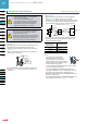
U-shaped
Convergent
Reflective
PM2
PM-24
421
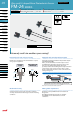
Ultra-small U-shaped Micro Photoelectric Sensor PM-24 SERIES
MICRO
PHOTO-
ELECTRIC
SENSORS
U-shaped
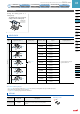
SPECIFICATIONS
Type
Ultra-small
With exible cable
Model No.
NPN output PM-□24 PM-□24-R
Item PNP output PM-□24P
–
Sensing range 5 mm 0.197 in (xed)
Minimum sensing object 0.8 × 1.8 mm 0.031 × 0.071 in opaque object
Hysteresis 0.05 mm 0.002 in or less
Repeatability 0.03 mm 0.001 in or less
Supply voltage 5 to 24 V DC ± 10 % Ripple P-P 10 % or less
Current consumption 15 mA or less
Output
<NPN output type>
NPN open-collector transistor
Maximum sink current: 50 mA
Applied voltage: 30 V DC or less (between output and 0 V)
Residual voltage: 0.7 V or less (at 50 mA sink current)
0.4 V or less (at 16 mA sink current)
•
•
•
<PNP output type>
PNP open-collector transistor
Maximum source current: 50 mA
Applied voltage: 30 V DC or less (between output and + V)
Residual voltage: 0.7 V or less (at 50 mA source current)
0.4 V or less (at 16 mA source current)
•
•
•
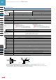
Utilization category DC-12 or DC-13
Output operation Incorporated with 2 outputs: Light-ON / Dark-ON
Response time
Under light received condition: 20 µs or less
Under light interrupted condition: 100 µs or less
(Response frequency: 1 kHz or more) (Note 2)
Operation indicator Vermilion LED (lights up under light received condition)
Environmental resistance
Pollution degree 3 (Industrial environment)
Ambient temperature (Note 3, 4)
–25 to +55 °C –13 to +131 °F (No dew condensation or icing allowed), Storage: –30 to +80 °C –22 to +176 °F
Ambient humidity 35 to 85 % RH, Storage: 35 to 85 % RH
Ambient illuminance Fluorescent light: 1,000 ℓx at the light-receiving face
EMC EN 60947-5-2
Voltage withstandability 1,000 V AC for one min. between all supply terminals connected together and enclosure
Insulation resistance 50 MΩ, or more, with 250 V DC megger between all supply terminals connected together and enclosure
Vibration resistance 10 to 2,000 Hz frequency, 1.5 mm 0.059 in amplitude in X, Y and Z directions for two hours each
Shock resistance 15,000 m/s
2
acceleration (1,500 G approx.) in X, Y and Z directions for three times each
Emitting element Infrared LED (Peak emission wavelength: 940 nm 0.037 mil, non-modulated)
Material Enclosure: PBT, Slit cover: Polycarbonate
Cable 0.09 mm
2
4-core cabtyre cable [PM-□24-R: 0.1 mm
2
exible, oil and heat resistant cabtyre cable (Note 5)], 1 m 3.281 ft long
Cable extension Extension up to total 100 m 328.084 ft is possible with 0.3 mm
2
, or more, cable.
Weight Net weight: 10 g approx.
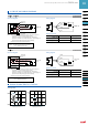
Notes: 1) Where measurement conditions have not been specied precisely, the conditions used were an ambient temperature of +23 °C +73.4 °F.
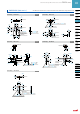
2) The response frequency is the value when the disc, given in the gure below, is rotated.
3)
In case the ultra-small type PM-□24(-R) is used at an ambient temperature of +50 °C +122 °F, or more, make sure to mount it on a metal body.
4) Take care that the exibility of the PM-□24-R cable is lost if the ambient temperature in –10 °C +14 °F or less.
5) The cable of PM-□24-R is a exible cable usable on a moving base. When the sensor is mounted on a moving base, x the sensor cable joint so that
stress is not applied to it. (Models other than the PM-□24-R cannot be used on a moving base.)
Disc
Disc
1.8 mm 0.071 in
1.6 mm 0.063 in
t = 0.2 mm 0.008 in
1.6 mm 0.063 in