Digital Device Display Operating Instructions Models No. PT-43LCX64/PT-50LCX64/PT-60LCX64 (USA) For assistance, please call : 1-888-VIEW PTV(843-9788) or, contact us via the web at: http://www.panasonic.com/contactinfo (Puerto Rico) For assistance, please call : 787-750-4300 or visit us at www.panasonicpr.com ATSC CERTIFIED * DIGITAL TELEVISION Three Important Reasons to Register Your Product Immediately! 1 Protect Your New Investment...
IMPORTANT SAFETY INSTRUCTIONS CAUTION RISK OF ELECTRIC SHOCK DO NOT OPEN WARNING: To reduce the risk of electric shock, do not remove cover or back. No user-serviceable parts inside. Refer servicing to qualified service personnel. This symbol warns the user that uninsulated voltage within the unit may have sufficient magnitude to cause electric shock. Therefore, it is dangerous to make any kind of contact with any inside part of this unit.
IMPORTANT SAFETY INSTRUCTIONS (CONTINUED) AS WITH ANY SMALL OBJECT, SD CARDS CAN BE SWALLOWED BY YOUNG CHILDREN. DO NOT ALLOW CHILDREN TO HANDLE THE SD CARD. CAUTION (1) This Device Display is intended to be used with the following TV stand: model TY-43LC14C for the PT 43LCX64, TY-50LC14C for the PT-50LCX64, and TY60LC14C for the PT-60LCX64. Use with other stands may result in the Device Display becoming unstable, possibly causing injury.
Dear Panasonic Customer Welcome to the Panasonic family of customers. We hope that you will have many years of enjoyment from your new Device Display. To obtain maximum benefit from your set, please read these Instructions before making any adjustments, and retain them for future reference. Retain your purchase receipt also, and record the serial number of your set in the space provided on the rear cover of these instructions. Visit our Panasonic Web Site for USA : www.panasonic.
Table of Contents Information Other Information ! Replacing the lamp unit .................................................................................... 91 Remote Control Quick Reference Guide (Operating peripheral equipment) ........... 92 Troubleshooting ................................................................................................ 99 Specifications .................................................................................................. 100 Warning Indicators .........
Before Using Receiver Location This Device Display is intended to be used with an optional stand or entertainment center. Consult your dealer for available options. Locate for comfortable viewing. Avoid placing where sunlight or other bright light (including reflections) will fall on the screen. Use of some types of fluorescent lighting can reduce Remote Control transmitter range. Adequate ventilation is essential to prevent internal component failure. Keep away from areas of excessive heat or moisture.
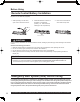
Before Using 1. Remote Control 2. Batteries 2 “AA” 3. RGB Cable (2 m) (EUR7627Z10) (LSJA0239-1 or LSJA0443) Getting Started Accessories Viewing position To optimize your viewing comfort, please follow the viewing guidelines shown in the diagrams below. If viewing for an extended period of time, sit as far back from the screen as possible. 70º 70º At least 1.6 m (PT-43LCX64) / 1.8 m (PT-50LCX64) /2.2 m (PT-60LCX64). 30º 30º At least 1.6 m (PT-43LCX64) / 1.8 m (PT-50LCX64) /2.
Before Using Remote Control Battery Installation Requires two AA batteries (supplied). 1. While pressing in on the catch, open cover in direction of arrow. 2. Install the batteries as shown in the battery compartment. (Polarity + or - must match the markings in the compartment). 3. Press cover in direction of arrow until it snaps shut. Two AA size CAUTION Incorrect battery installation can cause the batteries to leak, leading to personal injury and/or damage to the remote control.
Before Using CC (Closed Captioning) EAS (Emergency Alert System) OSD (On-Screen Display) MSO (Multiple system owner/operator) Dolby Digital This is a method of coding digital signals developed by Dolby Laboratories. Apart from stereo (2-channel) audio, these signals can also be multichannel audio. A large amount of audio information can be recorded on one disc using this method. Film and video DVD-Videos are recorded using either film or video.
Location of Controls Illuminated Remote Control POWER SAP 1 LIGHT 3 4 5 DBS RCVR CBL TV/VIDEO AS PEC T BBE CH VOL 22 VOL OK MENU 20 21 R E 19 AUX A - ANTENNA - B LL 7 8 DVD A EC 6 VCR MU T 2 TV 18 EXIT CH 23 9 24 10 1 2 3 4 5 6 7 8 R-TUNE 0 11 12 13 14 15 9 PROG 25 PIP MIN REW PLAY PIP MAX FF PAUSE STOP REC FREEZE TV/VCR PIP CH DVD/VCR CH SEARCH OPEN/CLOSE 26 27 PIP SPLIT MOVE SWAP 28 29 30 16 31 17 32 Note: This section describes TV mod
Location of Controls 2 3 4 5 6 7 8 9 10 11 12 13 14 15 16 17 Remote Keys POWER TV VCR, DVD, AUX, CBL, RCVR, DBS TV/VIDEO SD ASPECT MUTE VOL ◄► OK MENU Number R-TUNE PIP MIN REW PLAY PAUSE FREEZE TV/VCR PIP SPLIT 18 SAP 19 20 21 22 23 24 25 LIGHT ANTENNA A/B BBE RECALL EXIT CH ▲▼ PROG PIP MAX 26 FF 27 REC 28 STOP 29 SEARCH OPEN/CLOSE PIP CH ▲▼ 30 DVD/VCR CH 31 SWAP 32 MOVE DESCRIPTION Press to turn ON and OFF. Sets the remote to communicate with television.
Location of Controls Controls and Terminals on the Device Display Model PT-50LCX64 unit shown < FRONT > POWER button/ POWER indicator (P. 26) Volume up(+) / down(–) buttons (P. 34) Channel up / down buttons (P. 34) TV/VIDEO button (P. 34) A A Using your finger, slide Slot Cover in direction of arrow to open. Open LAMP indicator This indicator lights up when there is a malfunction with the lamp unit. (PP.
Location of Controls < REAR > Getting Started Model PT-50LCX64 unit shown < SIDE > Vent Vent DCM INTERFACE (POD INTERFACE) (p. 16) SERVICE ONLY Card slot used by a certified service technician only. Do not insert any memory card into this slot. DIGITAL AUDIO OUT terminal (P. 21) Antenna A, B terminal (PP. 14-16) RGB Input 2 terminal (P. 22) HDMI input terminal (PP. 24-25) RGB Input 1 terminal (P. 22) Input 3 terminals (P. 17) Input 1, 2 terminals (P. 17) Component signal input 1-3 terminals (P.
Installation Notes on connections • Turn off the power supply for all components before making any connections. • If the cables necessary for connecting a component to the system are not included with the component or available as an option, you may need to fashion a cable to suit the component concerned. • Read the instruction manual for each system component carefully before connecting it. • If there is a lot of jitter in the video signal input from the video source, the picture on the screen may flicker.
Installation For proper reception of digital and analog VHF/UHF channels, an external antenna is required. For best reception, an outdoor antenna is recommended. Connect home antenna to either ANT (A) or ANT (B) connection on back of the unit. Select Antenna mode for Cable/Antenna, Cable only, Antenna only or in Input Setup under Program Channel in Setup menu.
Installation Digital Cable Module Connection This module allows you to tune digital and high definition cable channels through the cable antenna. Consult your Cable company on the availability of this module (also called Point of Deployment (POD) module). 1 2 Connect the Cable antenna to ANT A/Cable In input on the back of the unit. Insert the DCM (Digital Cable Module) (upper side facing left) into the DCM INTERFACE (POD INTERFACE) slot on the back of the unit.
Installation Connects VCRs and other peripheral equipment (S-VHS VCR) Getting Started How to connect the “1, 2, 3” Input Terminals S-VIDEO AUDIO Similar connections are available at the INPUT 1, 2, 3 input terminals. (P. 13) (VHS VCR) VIDEO AUDIO Similar connections are available at the INPUT 1, 2, 3 input terminals. Notes: • Input 3 is located on the side of the unit. • Select the desired VIDEO input position by pressing the TV/VIDEO button. (P.
Installation How to connect the COMPONENT VIDEO Input Terminals Because each Y, PB, and PR signal is input independently, the Component signal allows for more accurate color reproduction. The Component signal output terminal indication will differ according to the output device ( Y, PB, PR). Please read the operating instructions included with the output device. DVD Player COMPONENT VIDEO AUDIO Notes: • Similar connections are available at the COMPONENT VIDEO INPUT 1-3 Terminals.
Installation You can connect a VCR to the AV OUT terminal to record the program you are viewing on-screen. An external monitor can also be connected to the AV OUT terminals. Connect the VCR as shown below. Recording Equipment (S-VHS /VHS VCR) Getting Started How to connect the AV OUT Terminals S-VIDEO Or VIDEO AUDIO Notes: • This unit contains Video and Audio Outputs for the purpose of recording television programming to VCR. Due to license restrictions, if a device (STB, DVD, etc.
Installation How to connect the Amplifier Analog Audio Out To listen to the audio through a separate stereo system, connect an external audio amplifier to AUDIO OUT on back of unit. Stereo System (A Stereo Amplifier and Speakers) AUDIO Note: AUDIO OUT terminals cannot be connected directly to external speakers. Audio Adjustments • Select Speakers Off in Audio menu under Other Adjust menu. • Set amplifier volume to the preferred level.
Installation Use the diagram below to connect the Digital Audio Output of your Device Display to a Dolby Digital decoder. Dolby Digital 5.1 channel surround sound delivers digital-quality sound.
Installation How to connect the RGB IN Terminals Connecting a PC to RGB IN COMPUTER RGB OUT AUDIO OUT Connect a cable which matches the audio output terminal on the computer. PC audio cable (M3 stereo mini pin) Conversion adapter (If necessary) RGB cable (D-SUB 15P) RGB IN Terminal (D-SUB 15P) Pin Layouts 11 12 13 14 15 6 7 1 8 2 9 10 3 4 Connection port view 5 Pin No. 1 2 3 4 5 6 7 8 Signal name R G B NC NC Ground for R Ground for G Ground for B Pin No.
Installation The table below lists the different types of RGB signals that can be input. If a signal which differs greatly from any of the types listed below is input, the picture image may not be displayed correctly, or a black background may be displayed. At this time,“ signal” will flash in the on-screen display for about 5 seconds. DTV Format Signals Personal Computer Signals Signal data Information menu display Mode type No. of dots (H X V) VGA400 (70 Hz) 640 X 400 31.47 70.
Installation How to connect the HDMI input terminal About HDMI HDMI is the first all digital consumer electronics A/V interface that supports several uncompressed standard, enhanced and high definition video format as well as all existing multi-channel audio formats. One jack supports both video and audio information. The HDMI/HDCP1 input can be connected to an EIA/CEA 861/861B2 compliant consumer electronic device, such as a set top box or DVD player equipped with a HDMI output connection.
Installation 1 Connect the HDMI output from the set top box or a DVD player to the HDMI input on the back of the unit. 2 Press TV/VIDEO on the Remote Control to select HDMI input. • If you cannot display the picture because your Digital Set Top Box does not have a Digital Out terminal setting, use the Component Video Input (or the S-Video Input or Video Input). In this case, the picture will be displayed as an analog signal.
Power ON / OFF Turning the Power ON and OFF Always be sure to follow the procedure given below to turn the Device Display power ON and OFF. • The lamp cooling fan will continue to operate for approximately 1 minute after the power is turned off. At the same time, the POWER indicator will blink Red. Do not disconnect the power cord from the outlet and do not open the circuit breaker (unless necessary) while the cooling fan is still operating.
Power ON / OFF First Time Setup For your convenience, First Time Set up menu will be displayed on screen when the set is turned on for the first time. If needed, follow the menus and procedures displayed on-screen for setting up the features. Input Setup POWER SAP LIGHT TV VCR DVD DBS RCVR CBL AS PE C T R VOL LL CH VOL OK MENU EXIT CH F i r s t T i m e I n p u t S e t u p A u t o BBE A EC MU T No video will be displayed in this setup mode.
Basic Menu Navigation POWER SAP MENU 1 Pressing displays the Main Menu screen. LIGHT TV VCR DVD DBS RCVR CBL TV/VIDEO AS MENU PE C T BBE R E A EC CH VOL LL MU T AUX A - ANTENNA - B EXIT CH 1 2 3 4 5 6 7 8 R-TUNE Press Pressing MENU again displays previous level menu. to select the desired icon.
Basic Menu Navigation Continued from page 28. Press CH VOL VOL OK Continued from left column. to adjust or set desired menu item. Press to select desired sub-menu items. CH VOL OK VOL CH CH Color +32 SELECT h o i D o D D er Adjust lor Temp deo NR Y/C lor Matrix I/P 1 EXIT Normal Off On SD Off On Note: For Other Adjust sub-menu. Press to select Other Adjust. CH VOL Press VOL OK to select desired sub-menu items.
Tuning channels Automatic channel setting Automatically searches and adds receivable channels to memory. Press MENU to display the Main Menu screen. POWER SAP 1 Press to select Setup icon. CH LIGHT TV VCR DVD DBS RCVR CBL TV/VIDEO AUX PE C T R A EC LL CH VOL OK MENU Press to display the options in the Setup menu. BBE E VOL VOL OK CH A - ANTENNA - B AS MU T VOL EXIT CH 2 CH VOL VOL OK Press to select Program CH icon.
Tuning channels 5 CH VOL OK VOL CH Press to start Auto Scan. Notes: • If Cable Only, Antenna Only or Antenna/Cable is selected and DCM (Digital Cable Module) is not in, the Auto Scan will perform Scan All. • If Cable Only is selected and DCM is in, Auto scan will be skipped. • If Cable/Antenna is selected and DCM is in, Antenna (B) Analog & Digital Auto scan will be performed. 1 2 Select Auto Scan and press OK to enter the sub menu. Press to select Auto Scan item.
Tuning channels Manual channel setting Use this procedure when changing setting of receiving channels or changing the channel display. To add or delete channels from either channel list (A/B) manually. Press MENU to display the Main Menu screen. POWER SAP LIGHT TV VCR DVD DBS RCVR CBL TV/VIDEO 1 VOL AUX Press to select Setup icon. CH VOL OK A - ANTENNA - B CH PE C T R E LL CH VOL VOL OK MENU Press to display the options in the Setup menu.
Tuning channels 6 To add channel Press to select Channel Add. CH VOL OK VOL P r o g r a m I n p u t A u t o C h a n n e l S e t u p S c a n M a n u a l P r o g r a m S i g n a l M e t e r RF Input Channel Add Channel Del Antenna (A) A:9 A:3 SELECT CHANGE to MENU return OK EXIT Press OK to add L a n g u a g e CH VOL OK Basic Operation Press to select CH. CH VOL CH Press to add channels to memory. To delete channel Press to select Channel Del.
Device display operation Operation can be done from the Device Display. POWER button/ POWER indicator Volume up(+) / down(–) buttons Channel up / down buttons TV/VIDEO button Remote Control Sensor POWER SAP Press to operate the Device Display with the Remote Control.
Device display operation Channel and Program Tuning Channel and Program tuning in digital television differs from conventional television. With DTV, many programs can exist within a single 6 MHz channel. These channels behave as sub-channels within a single channel. When tuning to a digital channel, the Device Display will also tune to a program and will indicate the channel and program in the on-screen Channel Banner display.
Device display operation Rapid Tuning Switches between the current and last channel or program. POWER SAP R-TUNE Photo Viewer or input modes. LIGHT TV VCR DVD DBS RCVR CBL TV/VIDEO BBE R A EC CH LL MU T PE C T E VOL VOL OK MENU CH EXIT 1 2 3 4 5 6 7 8 R-TUNE 36 AUX A - ANTENNA - B AS A - ANTENNA - B A/B button switches between the two RF antenna inputs, if connected. The last tuned channel in memory of the respective RF input is displayed.
Device display operation Changing the input signal The input source for picture signals can be changed by pressing TV/VIDEO, SD on the Remote Control or TV/VIDEO on the unit. Remote Control The input mode changes each time this button is pressed. TV *1 If SKIP is set as the Input Label setting of Channel Caption, the mode will not be changed. (See page 71.
Device display operation Unit Status display POWER Press the RECALL, Channel UP/DOWN or TV/VIDEO button, except when the MENU screen is displayed, to display current unit status information.
Device display operation Add FAV / Del FAV feature This feature lets you add channels to or delete channels from the Favorite channel list. Tune to the desired channel to be added or deleted. 2 To add a favorite channel Press RECALL while viewing an unregistered channel to display Add FAV in the CH Banner. A:135-99998 ABC 480i FULL VIVID 480i FULL VIVID Basic Operation 1 Add FAV Press OK to add the channel.
ASPECT Controls The color monitor will allow you to enjoy viewing the picture at its maximum size, including wide screen cinema format picture. The aspect mode changes each time ASPECT is pressed.
ASPECT Controls Mode Picture Explanation 4 4:3 4:3 3 JUST 9 JUST mode will display a 4:3 picture at maximum size but with aspect correction applied to the center of the screen so that elongation is only apparent at the left and right edges of the screen. The size of the picture will depend on the original signal. 16 ZOOM ZOOM 9 ZOOM mode magnifies the central section of the picture. 9 FULL will display the picture at its maximum size but with sight elongation.
Mute / Freeze / SAP Sound mute Useful when answering the phone or receiving unexpected visitors POWER SAP LIGHT TV VCR DVD DBS RCVR CBL TV/VIDEO AUX A - ANTENNA - B AS PE C T BBE R E A EC CH VOL LL MU T Press this button to mute the sound. Press again to reactivate sound. Sound is also reactivated when power is turned off or volume level is changed.
Mute / Freeze / SAP In analog mode, SAP Press SAP button to select the desired audio mode as described below. (Arrow shows selection.) • Each press of SAP button will change the audio mode as shown below. • “SAP” is selected with first press of SAP button. Example: Press SAP STEREO SAP MONO Press SAP STEREO SAP MONO Press SAP Receivable Broadcast Types The following are possible broadcast types with their accompanying on-screen displays.
Picture in Picture (PIP) Screen This unit includes a two-tuner Picture In Picture (PIP) feature. This allows you to watch two (2) live broadcasts at the same time with or without an external video source, such as a VCR, cable box, etc.
Picture in Picture (PIP) Screen Changing the channel of the PIP screen PIP CH DVD/VCR CH Press to select the desired channel. Example: During Main screen NORMAL Swapping Main and PIP screens SWAP Press to swap. Example: During Main screen NORMAL A:5 A:5 A:5 A:3 Basic Operation A:6 A:3 Move PIP screen You can move the PIP screen to four positions. Selecting the screen size for PIP screen MOVE You can choose PIP screen size of 3 magnifications. PIP MAX FF Press to large PIP screen size.
Split screen Splitting the screen POWER SAP SPLIT Press to split. (The previously selected screen appears on the left.) LIGHT TV VCR DVD DBS RCVR CBL TV/VIDEO AS PEC T BBE R E LL CH VOL Left screen (Main picture) VOL OK MENU CH EXIT 1 2 3 4 5 6 7 8 R-TUNE PIP MIN REW 9 0 PIP MAX FF PAUSE STOP REC FREEZE TV/VCR PIP CH DVD/VCR CH SEARCH OPEN/CLOSE SPLIT Right screen (Sub picture) Returning to one screen SPLIT Press to return.
Split screen Changing the channel of the right screen PIP CH DVD/VCR CH Press to select the desired channel. Swapping left and right screens SWAP Example: During SPLIT SCREEN NORMAL Example: During SPLIT SCREEN NORMAL A:3 A:5 A:6 A:5 A:3 Basic Operation A:5 Example: During SPLIT SCREEN NOR MAL (RGB input) Select desired input mode of the Right screen TV/VIDEO Press to swap. A:5 RGB1 Press to select the desired input mode.
Searching for the desired channel (Channel search) Channel search displays each channel, in order, as a paused image. Channels are displayed from the left top to the right bottom in order. When it reaches the right bottom, the next channel is displayed at the left top, overwriting the previously displayed channel. SEARCH OPEN/CLOSE POWER SAP When SEARCH/OPEN/CLOSE is pressed during single screen.
Favorite Channel Feature Allows you to create a Favorite channel list from Antenna (A) or Antenna (B). Press MENU to display the Main Menu screen. POWER SAP LIGHT TV VCR DVD DBS RCVR CBL 1 VOL TV/VIDEO Press to display the options in the Channel menu. R LL CH VOL OK MENU CH BBE E VOL EXIT CH 2 1 2 3 4 5 6 7 8 9 VOL CH Press to display the Favorite menu. PIP MAX FF PAUSE STOP REC FREEZE TV/VCR PIP CH DVD/VCR CH SEARCH OPEN/CLOSE MOVE 3 Press to select each item.
Picture Adjustments Press MENU to display the Main Menu screen. POWER SAP LIGHT TV VCR DVD DBS RCVR CBL 1 VOL TV/VIDEO Press to display the Picture screen. R LL CH VOL OK MENU CH BBE E VOL VOL A EC MU T PE C T OK AUX A - ANTENNA - B AS Press to select Picture icon. CH EXIT CH 2 Press to select each item.
Picture Adjustments ■ Color: ■ Tint: ■ Brightness: ■ Picture: ■ Sharpness: ■ Contrast: ■ R Level: ■ G Level: ■ B Level: CH VOL OK VOL CH 4 EXIT Adjust to desired level while viewing picture through the menu overlay. Press MENU or wait a few seconds to return to the previous menu screen. Press ◄ button. Press ► button. Press ◄ button. Press ► button. Contrast Press ◄ button. G Level B Level Press ► button. Press ◄ button. Press ► button. Press ◄ button. Press ► button. Press ◄ button.
Adjusting screen position and size POWER SAP 1 Press to select the screen mode. LIGHT TV VCR DVD DBS RCVR CBL TV/VIDEO AS PEC T BBE R E A EC CH VOL Press MENU to display the Main Menu screen. Press to select Setup icon.
Adjusting screen position and size Adjustment Button Adjustment Details item H Position Press ► button. The image moves to the right. Note Press ◄ button. The image moves to the left. V Position Press ► button. The image moves up. Press ◄ button. The image moves down. H Width Press OK button. If noise appears on the ends of the image in Shrink, switch to Enlarge. Only JUST mode (Shrink) (Enlarge) If noise appears on the ends of the image in Widen, switch to Narrow.
Audio Adjustments Press MENU to display the Main Menu screen. POWER SAP LIGHT TV VCR DVD DBS RCVR CBL TV/VIDEO PE C T VOL AUX VOL CH Press to display Audio menu. R A EC LL CH VOL OK MENU OK BBE E VOL Press to select Audio icon. CH A - ANTENNA - B AS MU T 1 EXIT CH SELECT 2 CH VOL OK VOL Normal is displayed at default. CH 1 2 3 4 5 6 7 8 R-TUNE 3 Press to select each item.
Audio Adjustments Other Adjust While in the Audio menu screen, select Other Adjust and press OK to display the Other Adjust sub-menu. ■ Speaker: This feature is used to turn TV speakers On or Off. • On - TV speakers operate normally. • Off - TV speakers off. ■ Surround: Enhances audio response when listening to stereo. ■ Audio Select: Perform input switching of analog audio input and digital audio input when using the HDMI terminal.
Lock Feature This Device Display incorporates V-CHIP technology to block the viewing of movies and television programs according to the rating category. There are four (4) Content Advisory Categories: MPAA (Motion Picture Association of America), TV Parental Guidelines Ratings, Canadian English Language Ratings and Canadian French Language Ratings. These categories are used as guidelines for blocking the programs. The default mode for the Lock category is the Unlocked state.
Lock Feature Lock Set Press MENU to display the Main Menu screen. 1 Press to select Lock icon. CH VOL OK VOL CH Press to display the options in the Lock menu. 2 1 2 3 4 5 6 7 8 9 Press number keys to enter your secret code. P a s s w o r d E n t e r P a s s w o r d ____ to MENU return EXIT 0 3 Press to select the Lock Set icon. CH VOL OK VOL CH 4 ■ Mode: To prevent video games, VCR tapes and all channels and video modes from being viewed.
Lock Feature Channel Lock POWER SAP LIGHT TV VCR DVD DBS RCVR CBL TV/VIDEO A - ANTENNA - B AS PE C T BBE R E A EC CH 1 VOL VOL Press to select Lock icon. CH LL MU T AUX This option lets you block out up to four (4) channels from each RF input (Antenna (A) and (B)) regardless of the program rating. Password is required to view these blocked channels. Press MENU to display the Main Menu screen. OK VOL VOL OK CH MENU EXIT CH Press to display the options in the Lock menu.
Lock Feature Block Program This feature allows you block movies and television programs based on the MPAA, U.S. TV Ratings system, Canadian English Language Ratings and Canadian French Language Ratings. ■ MPAA: The MPAA uses standard movie ratings to block unwanted movies from being displayed. Press MENU to display the Main Menu screen. 1 Press to select Lock icon. CH VOL OK VOL CH Press to display the options in the Lock menu. 2 Press number keys to enter your secret code.
Lock Feature Block Program (Continued). POWER SAP LIGHT TV VCR DVD DBS RCVR CBL TV/VIDEO AS PE C T BBE R E A EC CH VOL VOL OK MENU number keys to enter your secret code. 1 Press In Lock menu, select Block Program and press OK to display the Block Program menu. LL MU T AUX A - ANTENNA - B U.S. TV Rating The TV Parental Guidelines has 7 levels of age-based ratings that can be selected.
Lock Feature Block Program (Continued). POWER SAP LIGHT TV VCR DVD DBS RCVR CBL TV/VIDEO CT BBE number keys to enter your secret code. 1 Press In Lock menu, select Block Program and press OK to display the Block Program menu. R E A EC CH VOL LL MU T AUX A - ANTENNA - B PE AS Canadian English Language Ratings The V-CHIP used in this TV model allows you to block various types of movies and television programs based on the two rating systems used in Canada.
Lock Feature Block Program (Continued). POWER SAP LIGHT TV VCR DVD DBS RCVR CBL TV/VIDEO PE C T BBE LL CH VOL VOL OK MENU number keys to enter your secret code. 1 Press In Lock menu, select Block Program and press OK to display the Block Program menu. R E A EC MU T AUX A - ANTENNA - B AS Canadian French Language Ratings The V-CHIP used in this TV model also lets you block or unblock Canadian French programs according to various ratings categories. 2 VOL EXIT CH Press to select C.
Lock Feature How long? This feature allows you lock the television input sources for a specific period of time. Available selections are: 12 hours, 24 hours, 48 hours or Always. Press MENU to display the Main Menu screen. 1 Press to select Lock icon. CH VOL OK VOL CH Press to display the options in the Lock menu. 2 3 Press number keys to enter your secret code. Press to select the How Long? icon. CH VOL OK VOL CH Press to display the How Long? menu. 4 Press to select Time.
Lock Feature Blocking Messages Various Blocking messages are displayed on-screen depending upon the type of blocking you have selected in the Lock menu. When Game Lock or Channel Lock is selected: Following message is displayed if you attempt to tune to channels or select video. Channel Locked. Press OK to enter password for temporary unlock. When the rating level is exceeded Following message is displayed if the program you are viewing exceeds the set rating level.
Lock Feature US MOVIES RATINGS: NR G Not Rated by MPAA. GENERAL AUDIENCES. All ages admitted. PARENTAL GUIDANCE SUGGESTED. Some material may not be suitable for children. PARENTS STRONGLY CAUTIONED. Some PG-13 material may be inappropriate for children under 13. RESTRICTED. Under 17 requires R accompanying parent or adult guardian. PG NC-17 NO ONE 17 AND UNDER ADMITTED. X ADULTS ONLY.
Closed Caption Feature The Device Display includes a built-in decoder capable of visually displaying the audio portion of broadcasts which feature Closed Captioning (CC). You can set your preferences for both digital and analog Closed Captioning. POWER SAP LIGHT TV VCR DVD DBS RCVR CBL TV/VIDEO A - ANTENNA - B AS PE C T LL Press to display the options in the Setup menu. EXIT CH 1 2 3 4 5 6 7 8 Press to select Closed Caption icon.
Closed Caption Feature Analog This option lets you choose the closed caption service you desire. 1 2 In Closed Caption menu, select Analog. C l o s e d CH VOL VOL OK CH Press to select the desired setting: CC1, CC2, CC3, CC4, T1, T2, T3 or T4.
Closed Caption Feature Continued from page 67. Size: Automatic Normal Large Small Automatic None Raised Drop Shadow Uniform Depressed POWER SAP LIGHT TV VCR DVD DBS RCVR CBL TV/VIDEO A - ANTENNA - B AS PE C T BBE R E A EC CH VOL LL MU T Style: AUX VOL OK MENU EXIT CH Colors: closed captioning sub-menu, select Colors and press 1 InOKdigital to display the colors sub-menu. Press to select 2 each item. CH 1 2 3 4 5 6 7 8 9 R-TUNE CH Press to select desired setting.
Channel Caption Feature To enter preset and manual labels for desired stations. Also, to enter input labels for video inputs. ■ Preset Labels: To enter channel numbers for popular TV stations. POWER SAP LIGHT TV VCR DVD DBS RCVR CBL TV/VIDEO Press MENU to display the Main Menu screen. 1 AUX VOL A - ANTENNA - B Press to select Channel icon. CH OK VOL CH CT Press to display the options in the Channel menu.
Channel Caption Feature (Continued) ■ Manual Labels: To enter numbers and captions manually. POWER SAP LIGHT TV VCR DVD DBS RCVR CBL TV/VIDEO AS PE C T VOL Press to enter Manual Labels listed. LL EXIT CH C a p t i o n s M a n u a l I n p u t 1 2 3 4 5 6 7 8 9 3 PROG 0 PIP MIN REW PLAY PIP MAX FF PAUSE STOP REC FREEZE TV/VCR PIP CH DVD/VCR CH SEARCH OPEN/CLOSE SPLIT VOL CH P r e s e t PIP OK VOL OK R-TUNE Press to select Manual Labels.
Channel Caption Feature (Continued) 7 Repeat 4, 5, and 6 until all captions are added. Up to (7) characters per channel. 8 Use the remote number keys to select desired channel. 9 EXIT Note: To delete the Channel Caption, highlight the first character and press CH ▲ or CH ▼ until no character is displayed. Move to the next character and repeat the process. After all characters have been deleted, press OK to enter the choice. Press to exit menu.
Color Temp Feature To increase or decrease Warm (red) and Cool (blue) colors to suit personal preferences. Press MENU to display the Main Menu screen. POWER SAP LIGHT TV VCR DVD DBS RCVR CBL TV/VIDEO PE C T VOL CH Press to display Picture menu. A EC LL VOL OK EXIT CH SELECT 2 1 2 3 4 5 6 7 8 9 PLAY PIP MAX FF PAUSE STOP REC FREEZE TV/VCR PIP CH DVD/VCR CH SEARCH OPEN/CLOSE SPLIT OK VOL CH Press to display the Other Adjust sub-menu.
Video NR (Noise Reduction) Feature In the event of weak signal conditions, the Video NR circuitry reduces noise in the luminance channel. It is important to note that Video NR should remain Off for maximum picture detail when receiving a strong signal or viewing high-quality video. Press MENU to display the Main Menu screen. POWER SAP LIGHT TV VCR DVD DBS RCVR CBL 1 VOL TV/VIDEO LL VOL OK EXIT CH 1 2 4 5 7 8 R-TUNE 2 Press to select Other Adjust.
3D Y/C Feature Accurate separation of the picture’s brightness and color signals allows you to enjoy a beautiful picture. Press MENU to display the Main Menu screen. POWER SAP LIGHT TV VCR DVD DBS RCVR CBL TV/VIDEO VOL AUX PE C T CH A EC Press to display Picture menu. LL VOL OK EXIT CH 2 1 2 3 4 5 6 7 8 R-TUNE VOL OK VOL CH 9 0 PLAY PIP MAX FF PAUSE STOP REC FREEZE TV/VCR PIP CH DVD/VCR CH SEARCH OPEN/CLOSE SPLIT Press to select Other Adjust.
Setting when 480p signals are input through COMPONENT VIDEO INPUT Adjust 480p signals to achieve a natural color from digital equipment connected to COMPONENT VIDEO INPUT (Y, PB, PR input terminals). Press MENU to display the Main Menu screen. POWER SAP LIGHT TV VCR DVD DBS RCVR CBL TV/VIDEO 1 AUX Press to select Picture icon. CH VOL A - ANTENNA - B OK VOL CH CT BBE R E A EC CH VOL VOL OK MENU EXIT CH 1 2 3 4 5 6 7 8 9 R-TUNE Press to select Other Adjust.
3D I/P Feature Film media (taken at 24 frames per second) is faithfully reproduced on the Device Display. Press MENU to display the Main Menu screen. POWER SAP LIGHT TV VCR DVD DBS RCVR CBL TV/VIDEO 1 AUX VOL A - ANTENNA - B Press to select Picture icon. CH OK VOL CH CT BBE R E A EC CH VOL VOL OK MENU EXIT CH 1 2 3 4 5 6 7 8 R-TUNE Press to select Other Adjust.
Automatically changing screen size If the received signal contains screen size specifications in RF, VIDEO INPUT (1–3) or COMPONENT VIDEO INPUT (1–3), the screen size is automatically changed. Press MENU to display the Main Menu screen. POWER SAP LIGHT TV VCR DVD DBS RCVR CBL TV/VIDEO PE C T CH A EC LL 1 2 3 4 5 6 7 8 9 Press to display Picture menu. 2 Press to select Other Adjust.
RGB IN Input Feature Set the signal to be input to the Device Display’s RGB IN terminal. Most analog RGB IN signals are selected automatically. When RGB input signal is VGA 60Hz from PC or 480p from other equipment, you must manually switch to the desired input. Press MENU to display the Main Menu screen. POWER SAP LIGHT TV VCR DVD DBS RCVR CBL TV/VIDEO 1 PE C T VOL R A EC Press to display Picture menu. LL CH VOL OK MENU OK CH BBE E VOL Press to select Picture icon.
Sleep Timer Feature The Device Display can be set to shut itself off at a preselected time. Press MENU to display the Main Menu screen. POWER SAP LIGHT TV VCR DVD DBS RCVR CBL TV/VIDEO PE C T VOL CH A EC LL 1 2 3 4 5 6 7 8 9 2 OK CH VOL OK CH PROG 0 PLAY PIP MAX FF PAUSE STOP REC FREEZE TV/VCR PIP CH DVD/VCR CH SEARCH OPEN/CLOSE MOVE MENU VOL Press repeatedly to select the desired time.
Information You can display the input signal type. Display items differ depending on the input signal. Press MENU to display the Main Menu screen. POWER SAP LIGHT TV VCR DVD DBS RCVR CBL TV/VIDEO CT VOL AUX CH Press to display the options in the Setup menu. A EC LL CH VOL OK MENU EXIT CH 2 1 2 3 4 5 6 7 8 R-TUNE VOL Press to display the Other Adjustment menu. 9 PROG 0 PLAY STOP PIP CH DVD/VCR CH SPLIT OK CH PIP MAX FF 3 MOVE REC Press to select Information.
Demo Mode Feature Function demonstrations of this unit are displayed in Demo Mode. Press MENU to display the Main Menu screen. POWER SAP LIGHT TV VCR DVD DBS RCVR CBL TV/VIDEO VOL AUX PE C T CH Press to display the options in the Setup menu. A EC LL VOL OK EXIT CH 2 CH VOL 1 2 3 4 5 6 7 8 R-TUNE 0 PIP MAX FF PAUSE STOP REC CH Press to display the Other Adjustment menu. MOVE 3 SEARCH OPEN/CLOSE Press to select Demo Mode.
Signal Meter Feature Displays the signal strength of the ATSC digital channel in either Antenna (A) or Antenna (B). Press MENU to display the Main Menu screen. POWER SAP LIGHT TV VCR DVD DBS RCVR CBL TV/VIDEO PE C T VOL CH Press to display the options in the Setup menu. R A EC LL CH VOL OK 2 CH VOL MENU VOL OK AUX BBE E VOL Press to select Setup icon. CH A - ANTENNA - B AS MU T 1 VOL OK Press to select Program CH icon.
Switching languages for display The language of the projection display is set to English as the factory setting. To select one of 3 different languages for on-screen displays, follow the instructions below. Press MENU to display the Main Menu screen. POWER SAP LIGHT TV VCR DVD DBS RCVR CBL TV/VIDEO PE C T VOL OK AUX CH Press to display the options in the Setup menu. R A EC LL CH VOL OK MENU VOL BBE E VOL Press to select Setup icon.
Cable Module Info This menu is used to provide information when a DCM (Digital Cable Module) is inserted into the DCM INTERFACE (POD INTERFACE) slot in the back of the projection television. If no DCM is present and you try to access the Cable Module Info, the message“ Cable Module not present” will be displayed on screen. To receive the features offered by your cable company, you may have to subscribe to those services. Press MENU to display the Main Menu screen.
About Screen The About screen displays assorted information about the Device Display. Please have this information when calling Customer Care Center. Press MENU to display the Main Menu screen. POWER SAP LIGHT TV VCR DVD DBS RCVR CBL TV/VIDEO 1 AUX Press to select About icon. CH VOL OK VOL A - ANTENNA - B CH BBE R E A EC CH VOL VOL OK MENU Press to display About menu.
Photo Viewer (SD Card/PC Card) Still image data (JPEG) made with a digital camera, digital video camera, or PC can be played back using an SD Card/PC Card. WARNING As with any small object, SD cards can be swallowed by young children. Do not allow children to handle the SD card. Displayable Image Formats: Baseline JPEG (80 x 60 ~ 5 120 x 3 840 pixels) Notes: • Some parts of an image may not be displayed or the image may be displayed on a smaller scale depending on the size of the image.
Photo Viewer (SD Card/PC Card) Compatible Card Insert the Card. SD Card slot SD Card Multi Media Card Front Card Slot (P. 12) PC Card slot Compact Flash* Smart Media* Memory Stick* xD Picture Card* • The media* listed in the right column above can be read via the PC Card in the PC Card adaptor. • Hard disk PC Cards, Flash ATA Cards, and other recorded media cannot be used. • Place the selected media onto the PC Card and then insert into the PC Card Slot.
Photo Viewer (SD Card/PC Card) MENU Area Operation POWER SAP 1 CH LIGHT TV VCR DVD DBS RCVR CBL TV/VIDEO OK VOL PE C T R A EC VOL VOL OK MENU SD/PC When both an SD Card and PC Card are inserted, the ◄► buttons can be used to select a card in the index area. 1 2 3 4 5 6 Index Area Operation 7 8 9 2 R-TUNE PROG 0 PLAY PIP MAX FF PAUSE STOP REC FREEZE TV/VCR PIP CH DVD/VCR CH SEARCH OPEN/CLOSE SPLIT Press to select icon.
Photo Viewer (SD Card/PC Card) Single Play Mode POWER SAP LIGHT TV VCR DVD DBS RCVR CBL TV/VIDEO AS PE C T BBE R E A EC CH VOL CH EXIT 1 2 3 4 5 6 7 8 R-TUNE 0 PLAY PIP MAX FF PAUSE STOP REC FREEZE TV/VCR PIP CH DVD/VCR CH SEARCH OPEN/CLOSE 1/6 SINGLE VIEW SCREEN MOVE Press ► : The next image is displayed. Press ◄ : The previous image is displayed. Press ▼ : Each press rotates image 90°.
Photo Viewer (SD Card/PC Card) Continued from page 89. Slide Show Mode Information Screen Display 1 Press OK: INFORMATION SCREEN is displayed. (Rotation angle is maintained.) Information Screen FILE DATE -MENUPAGE: START SINGLE SPEED :FAST SLIDE TRANSITION:NORMAL SD/PC P2000006 07/31/2003 Pressing EXIT returns to SINGLE VIEW SCREEN. Note: If a file name exceeds 8 characters, a file name different from the original is displayed.
Replacing the lamp unit The lamp unit is sold separately. To purchase a replacement, call the Panasonic accessory department, toll free at: 1-800-332-5368. Lamp unit Part No. : TY-LA1000 Lamp unit replacement period The Lamp is a consumable item and it’s life varies based on individual usage. Panasonic warranties the original Lamp for a period of 1 year from the date of purchase. THE LAMP NEEDS TO BE REPLACED, AND THE LAMP HOUR METER NEEDS TO BE RESET.
Remote Control Quick Reference Guide (Operating peripheral equipment) Programming The Remote The Universal Remote Control can be programmed to operate many manufacturers’ components, using the component function buttons for VCR, DVD, DBS, RCVR or AUX. Follow the procedures for programming your Remote Control with or without a code for the component. POWER SAP LIGHT TV VCR DVD DBS RCVR CBL TV/VIDEO 1 Confirm that the external component is plugged and operating. Turn the component off.
Remote Control Quick Reference Guide (Operating peripheral equipment) Programming Without A Code This procedure searches all codes and is called the “sequence method.” POWER SAP LIGHT TV VCR DVD DBS RCVR CBL TV/VIDEO POWER 1 Confirm that the external component is plugged in and on. Turn the component off. A - ANTENNA - B AS PE C T R LL CH Press OK and POWER together, for at least 5 seconds.
Remote Control Quick Reference Guide (Operating peripheral equipment) Infrared Codes Index The Remote Control is capable of operating many brands of peripheral equipment. Refer to page 92 and 93 for programming procedures. Notes: • The Remote Control memory is limited and therefore some models may not operate. The Remote Control is not designed to control all features available in all models. • After entering the proper infrared code, press the desired Mode Selection button on the Remote Control.
Remote Control Quick Reference Guide (Operating peripheral equipment) CABLE CONVERTER BOX AND DVD, CD PLAYERS Infrared Codes Index CBL CBL DVD DVD Codes For Cable Box Brand Code Codes For Cable Box (Contd.
Remote Control Quick Reference Guide (Operating peripheral equipment) CASSETTE PLAYERS, PERSONAL VIDEO RECORDERS, RECEIVERS, AMPLIFIERS, and DBS Infrared Codes Index AUX AUX Codes For Cassette Decks Brand Code Codes For Cassette Decks (Contd.
Remote Control Quick Reference Guide (Operating peripheral equipment) Operating Components with Remote Control Note: Refer to pages 10-11 for programming Remote Control procedure. Operating a DBS Program the Remote Control to use with DBS. Operating a VCR Program the Remote Control to use with VCR. TO DO THIS... PRESS TO DO THIS...
Remote Control Quick Reference Guide (Operating peripheral equipment) Operating Components with Remote Control Operating a Cassette Deck To operate a cassette deck, the Remote Control must be in AUX mode and be programmed with the appropriate code for your equipment. TO DO THIS... PRESS Operating a Receiver Program the remote to operate audio receiver. TO DO THIS...
Troubleshooting Before you call for service, determine the symptoms and make a few simple checks as shown below. Symptoms Power does not turn ON. No picture even if the power is turned ON. LAMP indicator blinks red. The POWER indicator flashes orange twice every 5 seconds. The TEMP indicator flashes 2 or 4 times every 5 seconds. The power turns OFF. The TEMP indicator flashes 5 times every 5 seconds. Power turns off while another indicator is flashing.
Specifications PT-43LCX64 Power Source AC 120 V, 60 Hz Power Consumption Power ON: Power OFF: LCD panels PT-50LCX64 PT-60LCX64 Approx. 240 W (When audio is at maximum) Approx. 20 W (When cooling fan is stopped) 0.9″ Poly silicon TFT LCD 0.
Warning Indicators This unit has indicators (lights on the front) to let you know the unit’s internal condition. (See page 12) Depending on the condition, the Lamp, Power, or Temp indicator will flash to alert you. In this case, turn unit off and follow the measures below. Indicator Temp Indicator Lamp Indicator Problem Possible Solution Flashes red 1 or 3 times every Power shuts off. 5 seconds. Symptom Malfunction Contact a service center. Flashes red 2 or 4 times every Power shuts off. 5 seconds.
Cleaning To ensure continued excellent performance by this product, periodic cleaning is recommended. The unit contains many plastic parts. For this reason DO NOT use benzine, thinner or other chemicals to clean the unit. Dust will accumulate on the picture screen. Please wipe with a soft cloth from time to time. If you use a chemically treated cloth, please be careful to follow the instructions that come with the cloth. DO NOT bring into contact with insecticide or other volatile substances.
Limited Warranty PANASONIC CONSUMER ELECTRONICS COMPANY, DIVISION OF MATSUSHITA ELECTRIC CORPORATION OF AMERICA One Panasonic Way Secaucus, New Jersey 07094 PANASONIC SALES COMPANY, DIVISION OF MATSUSHITA ELECTRIC OF PUERTO RICO, INC., Ave. 65 de Infantería, Km. 9.
This product utilizes the following so called “open source” software: (1) the software which is licensed under the GNU GENERAL PUBLIC LICENSE, (2) the software which is licensed under the GNU LESSER GENERAL PUBLIC LICENSE, and (3) software developed by the third parties and available under certain terms and conditions. For the software categorized as (1) and (2), please refer to the terms and conditions of the following GNU GENERAL PUBLIC LICENSE and GNU LESSER GENERAL PUBLIC LICENSE respectively.
These requirements apply to the modified work as a whole. If identifiable sections of that work are not derived from the Program, and can be reasonably considered independent and separate works in themselves, then this License, and its terms, do not apply to those sections when you distribute them as separate works.
10. If you wish to incorporate parts of the Program into other free programs whose distribution conditions are different, write to the author to ask for permission. For software which is copyrighted by the Free Software Foundation, write to the Free Software Foundation; we sometimes make exceptions for this. Our decision will be guided by the two goals of preserving the free status of all derivatives of our free software and of promoting the sharing and reuse of software generally. NO WARRANTY 11.
GNU LESSER GENERAL PUBLIC LICENSE Version 2.1, February 1999 Copyright (C) 1991, 1999 Free Software Foundation, Inc. 59 Temple Place, Suite 330, Boston, MA 02111-1307 USA Everyone is permitted to copy and distribute verbatim copies of this license document, but changing it is not allowed. [This is the fi rst released version of the Lesser GPL. It also counts as the successor of the GNU Library Public License, version 2, hence the version number 2.1.
TERMS AND CONDITIONS FOR COPYING, DISTRIBUTION AND MODIFICATION function or table used by this function must be optional: if the application does not supply it, the square root function must still compute square roots.) 0. This License Agreement applies to any software library or other program which contains a notice placed by the copyright holder or other authorized party saying it may be distributed under the terms of this Lesser General Public License (also called “this License”).
derivative work of the Library even though the source code is not. Whether this is true is especially significant if the work can be linked without the Library, or if the work is itself a library. The threshold for this to be true is not precisely defined by law. It may happen that this requirement contradicts the license restrictions of other proprietary libraries that do not normally accompany the operating system.
system and a licensee cannot impose that choice. This section is intended to make thoroughly clear what is believed to be a consequence of the rest of this License. SUSTAINED BY YOU OR THIRD PARTIES OR A FAILURE OF THE LIBRARY TO OPERATE WITH ANY OTHER SOFTWARE), EVEN IF SUCH HOLDER OR OTHER PARTY HAS BEEN ADVISED OF THE POSSIBILITY OF SUCH DAMAGES. 12.
END OF TERMS AND CONDITIONS How to Apply These Terms to Your New Libraries If you develop a new library, and you want it to be of the greatest possible use to the public, we recommend making it free software that everyone can redistribute and change. You can do so by permitting redistribution under these terms (or, alternatively, under the terms of the ordinary General Public License). To apply these terms, attach the following notices to the library.
Index 1080i.................................................................................18, 23 480i ..................................................................................18, 23 480p .................................................................................18, 23 720p .................................................................................18, 23 A Antenna A, B terminal ............................................................13 ASPECT button ...............................