
Brochure


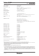

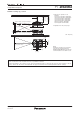


Standard setting-up position
Upper edge of projected image
432
(18)
ø60.5
(2-3/8)
298
(11-23/32)
*
1
*
2
Lower edge of projected image
Projected image
L
L
L
419–539
(16-1/2–
21-7/32)
*
2
560–680
(22-1/16–
26-25/32)
157
(6-3/16)
314
(12-3/8)
157
(6-3/16)
87.5
(3-7/16)
175
(6-7/8)
87.5
(3-7/16)
Projected image
HH
unit : mm (inch)
*1 When the lens protrudes to the
maximum.
212 mm (8-11/32) with the ET-D75LE6
125 mm (4-29/32) with the ET-D75LE10
121 mm (4-3/4) with the ET-D75LE20
121 mm (4-3/4) with the ET-D75LE30
124 mm (4-7/8) with the ET-D75LE40
254 mm (10) with the ET-D75LE8
203 mm (8) with the ET-D75LE50
*2 Adjustable in 40 mm (1-9/16) steps.
Caution:
• All construction work should be done by a qualied technician.
•When mounting to the ceiling, use the special mounting bracket. To prevent the projector from swaying or drop-
ping, attach the wire that is included with the projector between the mounting bracket and the ceiling.
NOTE:
Illustrations show the projector installed
using optional ceiling mount bracket
ET-PKD520H/ET-PKD520B and an optional
lens.This illustration is not drawn to scale.
PT-DS20K2
3-Chip DLP™ Projector
As of August 2015 6/13
SFD15M027