Functional Instructions DLP™Based Projector Commercial Use Model No. PT-DZ6710 PT-DZ6700 PT-DW6300 PT-D6000 The information of these instructions are shared use with multiple models of DZ6710 series, DZ6700 series, DW6300 series and D6000 series.
Contents Getting Started Getting Started Setting up.....................................................................3 Screen size and throw distance........................................ 3 Geometric adjustment ...................................................... 8 Front leg adjusters and throwing angle ............................ 9 Connections ..............................................................10 Before connection to the projector..................................
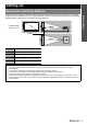
Setting up When planning the projector and screen geometry, refer to the figures below and the information on the following pages for reference. After the projector is roughly positioned, picture size and vertical picture positioning can be finely adjusted with the powered zoom lens and lens shifting mechanism.
Setting up J Projection distance by projection lens Q PT-DZ6710E/PT-DZ6700E Getting Started 16:10 (Unit: m) Lens type Standard zoom lens Lens names Through ratio SD 50'' 60'' 70'' 80'' 90'' 100'' 120'' 150'' 200'' 250'' 300 350'' 400'' 500'' 600'' SH 1.8 - 2.4:1 SW 0.673 2'2'' 0.808 2'7'' 0.942 3'1'' 1.077 3'6'' 1.212 3'11'' 1.346 4'4'' 1.615 5'3'' 2.019 6'7'' 2.692 8'9'' 3.365 11' 4.039 13'3'' 4.712 15'5'' 5.385 17'8'' 6.731 22'1'' 8.077 26'5'' 1.077 3'6'' 1.292 4'2'' 1.508 4'11'' 1.723 5'7'' 1.
Setting up Q PT-DW6300E 16:10 (Unit: m) SD 50'' 60'' 70'' 80'' 90'' 100'' 120'' 150'' 200'' 250'' 300'' 350'' 400'' 500'' 600'' Optional lens Lens names Standard zoom lens ET-DLE055 ET-DLE150 ET-DLE250 ET-DLE350 ET-DLE450 Through ratio 1.8 - 2.4:1 0.8:1 1.4 - 2.0:1 2.4 - 3.8:1 3.8 - 5.7:1 5.6 - 9.0:1 SH 0.673 2'2'' 0.808 2'7'' 0.942 3'1'' 1.077 3'6'' 1.212 3'11'' 1.346 4'4'' 1.615 5'3'' 2.019 6'7'' 2.692 8'9'' 3.365 11' 4.039 13'3'' 4.712 15'5'' 5.385 17'8'' 6.731 22'1'' 8.077 26'5'' SW 1.
Setting up Q PT-D6000E 16:10 (Unit: m) Lens type Getting Started SD 50'' 60'' 70'' 80'' 90'' 100'' 120'' 150'' 200'' 250'' 300 350'' 400'' 500'' 600'' Optional lens Lens names Standard zoom lens ET-DLE055 ET-DLE150 ET-DLE250 ET-DLE350 ET-DLE450 Through ratio 1.8 - 2.4:1 0.8:1 1.3 - 2.0:1 2.4 - 3.7:1 3.7 - 5.6:1 5.5 - 8.9:1 SH 0.762 2'6'' 0.914 2'11'' 1.067 3'6'' 1.219 3'11'' 1.372 4'6'' 1.524 5' 1.829 6' 2.286 7'6'' 3.048 10' 3.81 12'6'' 4.572 15' 5.334 17'6'' 6.096 20' 7.62 25' 9.
Setting up J Calculation formulas for projection distance by lens types Type Through ratio Aspect ratio Projection distance formula 16:10 Standard zoom lens 1.8 - 2.4:1 16:9 ET-DLE055 Fixed-focus lens ET-DLE150 Wide-angle zoom lens 0.8:1 16:10 16:9 16:10 1.3 - 1.8:1 16:9 16:10 ET-DLE250 Intermediate-focus zoom lens 2.4 - 4.0:1 16:9 16:10 ET-DLE350 Long-focus zoom lens 3.8 - 6.0:1 16:9 16:10 ET-DLE450 Ultra-long-focus zoom lens 5.8 - 8.
Setting up Geometric adjustment Getting Started VERTICAL KEYSTONE HORIZONTAL KEYSTONE (Side view) (Top view) Screen Screen (Top view) Screen HORIZONTAL ARC (Side view) Screen VERTICAL ARC (Side view) L2: Projection distance R2: Radius of the circle Arc Keystone and arc Keystone correction correction correction Screen (Top view) Screen L3: Projection distance R3: Radius of the circle Standard ET-DLE055 ET-DLE150 ET-DLE250 ET-DLE350 ET-DLE450 VERTICAL KEYSTONE Correction angle α (
Setting up Front leg adjusters and throwing angle STANDBY(RED)/ ON(GREEN) LAMP TEMP FILTER Getting Started You can screw up/down the front leg adjusters to control the angle of the projector for adjusting the throwing angle. NOTE: • Heated air comes out of the air exhaust port. Do not touch the air exhaust port directly.
Connections Before connection to the projector Getting Started Read and follow the operating and connecting instructions of each peripheral device. The peripheral devices must be turned off. Use cables that match each peripheral device to be connected. If the input signal is affected by signal jitter, the projected image may have poor image quality and timebase correction is effective. Confirm the type of video signals.
Connections Connecting example: Computers Computers Projector 1 Getting Started Control Projector 2 Control NOTE: • For the specifications of the RGB signals that can be applied from the computer, see the data sheet of the operating instructions that is provided with the projector. • If your computer has the resume feature (last memory), the computer may not function properly until the resume capability is disabled.
Menu Navigation Main menu and Sub-menu The menu options are structured and categorised. You can navigate through the menu with F G I H buttons. See “Menu Navigation” on page 12. The underlined items are factory default settings. Some default settings vary by the selected input signal. Sub-menu items vary according to the selected input signal. Some settings are adjustable without any signals.
Menu Navigation INSTALLATION COLOR MATCHING OFF 7 COLORS page 25 3 COLORS MEASURED COLOR CORRECTION OFF page 25 NORMAL page 25 HIGH SCREEN SETTING page 25 SCREEN FORMAT 16:10 16:9 4:3 ON page 25 OFF AUTO SETUP DEFAULT USER page 26 page 26 EDID1 EDID2(PC) DVI SIGNAL LEVEL 0-255:PC 16-235 SDI IN page 26 64-940 4-1019 ON-SCREEN DISPLAY page 26 OSD POSITION 1 4 7 2 5 8 3 6 9 2 5 3 6 OFF INPUT GUIDE ON OFF WARNING MESSAGE ON OFF BACK COLOR BLACK LOGO1 page 27 BLUE LOGO2 START
Menu Navigation SECURITY NETWORK SECURITY PASSWORD OFF page 35 ON SECURITY PASSWORD CHANGE page 35 page 35 DISPLAY SETTING OFF LOGO1 TEXT LOGO2 TEXT CHANGE MENU LOCK OFF page 35 page 36 ON MENU LOCK PASSWORD CONTROL DEVICE SETUP CONTROL PANEL ENABLE DISABLE REMOTE CONTROLLER ENABLE Settings ENGLISH - 14 DISABLE page 36 page 36 NETWORK SETUP page 37 HOST NAME DHCP IP ADDRESS SUBNET MASK DEFAULT GATEWAY STORE NETWORK CONTROL page 37 WEB CONTROL PJLink CONTROL COMMAND CONTROL COMMAND PORT
Menu Navigation Navigating through the menu J Displaying the main menu Press the MENU button to display the main menu. J Operating procedure 1. Press F G to scroll to the required main menu item and press the ENTER button to select. The selected item is highlighted in orange and the submenu is displayed. See “Main menu and Sub-menu” on page 12.
PICTURE menu Remote control COLOR You can adjust the colour saturation of the projected image. Call up the bar scale by pressing I, H or the ENTER button, and press I H to adjust the value. See “Navigating through the menu” on page 15. See “Main menu and Sub-menu” on page 12. PICTURE MODE Depending on the projection environment, you can use these preset parameter settings to optimise image projection. Press I H to cycle through the options.
PICTURE menu You can adjust the brightness of white area of the image. Call up the bar scale by pressing I, H or the ENTER button, and press I H to adjust the value. I H Setting range: 0 to +10 You can keep the projected image bright and vivid even in welllit rooms where the ambient light sources cannot be controlled, such as when a door opens or when window coverings fail to block out sunlight. Press I H to cycle through the options.
POSITION menu Remote control Q S1 AUTO Detects signals which contain S1 signal in input signal, and automatically switch the aspect ratio between 4:3 and 16:9. Effective with S-VIDEO signals. Q VID AUTO(PRI.) See “Navigating through the menu” on page 15. See “Main menu and Sub-menu” on page 12. Detects signals which contain video ID or S1 signal in input signal, and automatically switch the aspect ratio between 4:3 and 16:9. Detects video ID on a priority basis. Effective with S-VIDEO and NTSC signals.
POSITION menu J Menu items displaying pattern depends on signals Signals from RGB 1 IN/RGB 2 IN/DVI-D IN and SDI (PT-DZ6710E only) DEFAULT H THROUGH H 16:9 H 4:3 H H-FIT H V-FIT H HV-FIT H DEFAULT Signals from S-VIDEO IN VID AUTO H S1 AUTO H VID AUTO(PRI.
POSITION menu Q GEOMETRY:KEYSTONE Select KEYSTONE and press the ENTER button to display the options. VERTICAL KEYSTONE Q GEOMETRY:CURVED Select CURVED and press the ENTER button to display the options. LENS THROW RATIO Press I H to adjust throw ratio of the attached lens.
POSITION menu KEYSTONE (PT-DZ6700E/PT-DW6300E/PT-D6000E only) If the projector is aligned non-perpendicularly to the screen, or if the projection screen has an angled surface, you can correct keystone. VERTICAL KEYSTONE VERTICAL SUB KEYSTONE NOTE: Settings LINEARITY • When KEYSTONE setting is set, displayed menu or startup logo might be projected outside of the actual image area. • You can correct the distortion ± 30 degrees from the plane.
ADVANCED MENU Remote control See “Navigating through the menu” on page 15. See “Main menu and Sub-menu” on page 12. DIGITAL CINEMA REALITY You can improve the vertical resolution for PAL (or SECAM) 576i, NTSC 480i, 1080/50i or 1080/60i signals. Press I H to cycle through the options. AUTO OFF 25p FIXED 30p FIXED Detects PAL (or SECAM) 576i, 1080/50i, NTSC 480i and 1080/60i input signals and change the setting properly.
ADVANCED MENU EDGE BLENDING The built-in edge blending feature allows multiple projector images to be seamlessly overlapped by adding a brightness ramp. Press F G to select the required option. OFF Deactive ON Adds a brightness ramp to the overlapped area and adjustable the overlapping position manually. Q Adjusting with colour markers You can adjust with colour markers, which indicate the overlapping area. 1. Press G several times until MARKER is displayed. 2.
ADVANCED MENU Q Adjusting brightness around borderline of the image area You can adjust brightness around borderline of the image area to minimise the difference between the overlapping area and the image. Select BRIGHT ADJUST and press the ENTER button. Press F G to select a colour, and I H to change the value. BRIGHT INSIDE BRIGHT OUTSIDE OUTSIDE AREA INTERLOCKED: ON Adjust WHITE only. INTERLOCKED: OFF Adjust RED, GREEN and BLUE individually. Setting range: 0 to +255 INTERLOCKED: ON Adjust WHITE only.
DISPLAY OPTION menu Remote control COLOR CORRECTION You can adjust 6 colours and register the result for each of 4 types of signals, VIDEO, S-VIDEO, RGB and YPBPR/YCBCR. OFF COLOR MATCHING When multiple projectors are used simultaneously, you can adjust the difference of the colours. Press I H to cycle through the options. OFF 3 COLORS 7 COLORS MEASURED Deactive. Adjusting RGB gain of RED, GREEN and BLUE, and also GAIN of WHITE. Press I H to change the value and switch ON/ OFF the AUTO TEST PATTERN.
DISPLAY OPTION menu AUTO SETUP You can change the AUTO SETUP feature for specific signals. Press I H to cycle through the options and press the ENTER button to perform the AUTO SETUP. DEFAULT WIDE USER ON-SCREEN DISPLAY J OSD POSITION You can change the displaying position of the main menu. Press I H to cycle through the options.
DISPLAY OPTION menu BACK COLOR You can choose a blank screen colour for when the projector is idle. Press I H to select the required option. BLACK BLUE Displays black pattern. Displays solid blue. LOGO1 Displays user defined image. LOGO2 Displays PANASONIC logo. NOTE: • Special software is required to define the LOGO1 image. Contact to an Authorised Service Centre. STARTUP LOGO You can switch the logo on/off that is displayed when starting up the projector. Press I H to select the required option.
PROJECTOR SETUP menu Remote control HIGH ALTITUDE MODE If you use the projector at high elevation, the HIGH ALTITUDE MODE setting needs to be ON to set the fan speed high. Press I H to select the required option. See “Navigating through the menu” on page 15. See “Main menu and Sub-menu” on page 12. PROJECTOR ID The projector has an ID number setting function that helps the user to control multiple projectors either simultaneously or separately with a single remote control.
PROJECTOR SETUP menu LAMP SELECT You can select a lamp lighting pattern for using environment. Press I H to cycle through options, and the ENTER button. DUAL LAMP POWER The luminance of the projection lamp can be changed depending on user’s needs or the viewing conditions. All lamps will light. SINGLE Selects a lamp with shorter duration of use. LAMP1 Selects the Lamp unit 1. LAMP2 Selects the Lamp unit 2. HIGH Set when high brightness is necessary.
PROJECTOR SETUP menu STATUS FILTER COUNTER RESET You can see the status of the projector about the following items. Items Description INPUT Displays the input selection state. NAME Displays the input signal name. SIGNAL FREQUENCY Displays the frequency of the input signal. PROJECTOR RUNTIME Displays the projector runtime. LAMP1 Displays the lighting time of LAMP1. LAMP2 Displays the lighting time of LAMP2. INTAKE AIR TEMP. Displays the intake air temperature of the projector.
PROJECTOR SETUP menu You can set the time zone and correct the time and date of internal clock. TIME ZONE Select the current located time zone. ADJUST CLOCK Adjust YEAR, MONTH, DAY, HOUR and MINUTE by pressing I H, then select APPLY and press the ENTER button. SAVE ALL USERS DATA You can save various setting values as a backup to the internal memory of the projector. 1. Press the ENTER button. INITIALIZE You can reset the settings to the factory defaults by the selected mode. 1.
TEST PATTERN Remote control See “Navigating through the menu” on page 15. See “Main menu and Sub-menu” on page 12. TEST PATTERN You can use 7 test patterns to adjust the signal image. 1. Display an input signal image. 2. Press the MENU button to display the main menu. 3. Select TEST PATTERN menu. 4. Press I H to select the required test pattern. Press the ON SCREEN button to clear the screen if necessary.
SIGNAL LIST Remote control Q Displaying the signal list and the status 1. Select SIGNAL LIST in the main menu. 2. Press the ENTER button. Display the REGISTERED SIGNAL LIST. 3. Select the required signal data. 4. Press the ENTER button. Displays the REGISTERED SIGNAL STATUS. J SIGNAL LIST and SUB MEMORY LIST You can register a input signal as a SIGNAL LIST data, and several sets of adjusted settings for the signal as SUB MEMORY LIST data.
SIGNAL LIST J Managing the sub memory list You can restore the sub memory data when using signals from the same input source. Sub memory data contains the setting information of screen and image adjustments, such as BRIGHTNESS, CONTRAST or ASPECT. Q Registering the current settings to the list 1. Press I or H while the menu is cleared from the screen after adjustment. The signal must be registered before creating a sub memory data of the signal.
SECURITY menu See “Navigating through the menu” on page 15. See “Main menu and Sub-menu” on page 12. J Entering the SECURITY menu Every time when you apply to the SECURITY menu, you will be asked to perform the password operation. When you apply to the SECURITY menu before you change the password to your original, perform to input the following factory default password operation. Press F H G I F H G I and the ENTER button.
SECURITY menu MENU LOCK You can lock the MENU button function and the password will be asked to display the menu every time. OFF Deactivate the MENU LOCK system. ON Activate the MENU LOCK system. NOTE: • The factory default password is “AAAA”. • The factory default password is valid until you change the password in MENU LOCK PASSWORD menu. • When the projector is initialised, the password will be changed to the factory default setting, "AAAA".
NETWORK menu Remote control NETWORK CONTROL You can switch on/off the projector network controlling method. 1. Select the required item to change. 2. Press the ENTER button. 3. Use I H to change the settings. 4. Select STORE and press the ENTER button. NETWORK SETUP Make the initial network settings before using the network connection. 1. Select the required item to change. 2. Press the ENTER button. 3. Use F G I H to change the settings. 4. Select STORE and press the ENTER button.
Technical Information Network connection You can control the projector from a computer with web browser, for adjusting the menu settings, displaying status of the projector and transmission of E-mail messages if there is a problem with the projector. Computer LAN cable (straight) Projector LAN switch LAN cable (straight) NOTE: • A LAN cable is required to use the network function. A cross cable is required when connecting directly to a computer.
Technical Information Accessing with the web browser J Projector Control Window 1. Activate the web browser of the computer. 2. Enter the IP ADDRESS set by the projector into the URL input field of the web browser. J Change password Q Administrator mode 1. Select Administrator to change and click NEXT. See “NETWORK STATUS” on page 37. 3. Enter your user name and password.
Technical Information J Projector Control User account New setting User name Enter new user name. Password Enter new password. Password(Retype) Q Basic control Click the Basic control tab on the top. Enter the new password again. Indicates projecting status. Even when the screen is cleared by pressing the ON SCREEN button of the remote control, the information will be displayed. 3. Click OK. Q User mode Adjustable items A user can change password only.
Technical Information Remote control buttons*1 Web browser buttons Q Ping test Click the Ping test tag on the top. FUNCTION (Assignable functions in SUB MEMORY/SYSTEM the menu) DAYLIGHT VIEW/FREEZE/ See “FUNCTION BUTTON” on SIDE BY SIDE page 30. *1. See the operation instruction booklet that is provided with the projector. J Detailed set up Q Network config Click the Network config tag on the top. When all options are filled, click NEXT. The confirmation screen will be displayed.
Technical Information Q E-mail set up Items Click the E-mail set up tag on the top. When all options are filled, click Submit. Items Description E-MAIL ADDRESS 1/E-MAIL ADDRESS 2 Register the recipient E-mail address. E-MAIL ADDRESS 1/ Available to register up to 2 E-mail E-MAIL ADDRESS 2 address. Select NORMAL version or SIMPLE MAIL CONTENTS version of the contents. ERROR Sends E-mail when detects an error. LAMP1 RUNTIME Sends E-mail when lamp runtime of the lamp1 reaches the set time.
Technical Information J STATUS Parameter Q Projector status MAIN CPU BUS Trouble has occurred in the microcomputer circuitry. Consult your dealer. FAN Trouble has occurred in the fan or its drive circuit. Consult your dealer. INPUT AIR TEMPERATURE The input air temperature is too high. It may be that the projector is being used in an operating environment where the temperature is high such as near a heating appliance. OPTICS MODULE TEMPERATURE The temperature inside the projector is high.
Technical Information PJLinkTMprotocol The network function of the projector supports PJLink™ class 1, and the PJLink™ protocol can be used to perform projector setting and projector status query operations from a computer.
Technical Information Serial terminal The serial connector which is on the connector panel of the projector conforms to the RS-232C interface specification, so that the projector can be controlled by a personal computer which is connected to this connecter.
Technical Information J Basic format STX A D I 1 I 2 (2 bytes) ; C1 C2 C3 : Semicolon Colon (1byte) (1byte) P1 P2 - Pn 2 ID characters Parameter (2 bytes) (undefined length) Start ZZ, 01 to 64 and 0A to 0Z (1 byte) ID designate 3 command characters ETX End (3 bytes) (1 byte) NOTE: • No command can be sent or received for 10 to 60 seconds after the lamp starts lighting. Try sending any command after that period has elapsed.
Technical Information REMOTE 2 IN terminal Using the REMOTE 2 IN terminal provided on the connection terminals of the main unit, it is possible to operate the projector from a control panel etc. furnished in a distant location where infrared remote control signal cannot be received. Remote terminal External control Remote terminal/External control Standby ON LAMP Projector set up in a meeting room Control panel located in a different room J Pin assignments and control Pin No.
Technical Information SIDE BY SIDE function signal combination table Q Side by Side function signal combination table Main image RGB1 Still Sub image RGB2 Movie Still Movie DVI-D VIDEO S-VIDEO Still Movie SDI*1 Still N/A N/A OK OK OK OK OK OK OK Movie N/A N/A OK N/A N/A N/A OK N/A N/A Still OK OK N/A N/A OK OK OK OK OK Movie OK N/A N/A N/A N/A N/A OK N/A N/A VIDEO OK N/A OK N/A N/A N/A OK N/A N/A S-VIDEO OK N/A OK N/A N/A N/A OK N/A N/A
Technical Information Trademark acknowledgements Appendix VGA and XGA are trademarks of International Business Machines Corporation. S-VGA is a registered trademark of the Video Electronics Standards Association. The font used in the on-screen displays is a Ricoh bitmap font, which is manufactured and sold by Ricoh Company, Ltd. All other trademarks are the property of the various trademark owners.
Index A L ADVANCED MENU ........................................................ 22 AI .................................................................................... 17 ASPECT ......................................................................... 18 AUTO SETUP ................................................................ 26 AUTO SIGNAL ............................................................... 25 B LAMP POWER ................................................................
Index Serial Basic format ............................................................... 46 Cable specifications .................................................... 46 Communication settings ............................................... 45 Control commands ...................................................... 46 Pin assignments ......................................................... 45 Serial terminal ................................................................. 45 SERVICE PASSWORD .............
Printed in Japan S0209-1039B