Operating Instructions Functional Manual DLPTM Projector Commercial Use Model No. PT-DW740E PT-DW740EL PT-DX810E PT-DX810EL Thank you for purchasing this Panasonic product. ■■ This manual is common to all the models regardless of suffixes of the Model No.
Read this first! Read this first! WARNING: THIS APPARATUS MUST BE EARTHED. WARNING: To prevent damage which may result in fire or shock hazard, do not expose this appliance to rain or moisture. Machine Noise Information Ordinance 3. GSGV, January 18, 1991: The sound pressure level at the operator position is equal or less than 70 dB (A) according to ISO 7779. WARNING: 1. Remove the plug from the mains socket when this unit is not in use for a prolonged period of time. 2.
Be sure to read “Read this first!” Read this first! IMPORTANT: THE MOULDED PLUG (U.K. only) FOR YOUR SAFETY, PLEASE READ THE FOLLOWING TEXT CAREFULLY. This appliance is supplied with a moulded three pin mains plug for your safety and convenience. A 13 amp fuse is fitted in this plug. Should the fuse need to be replaced, please ensure that the replacement fuse has a rating of 13 amps and that it is approved by ASTA or BSI to BS1362. or the BSI mark on the body of the fuse.
Read this first! WARNING: POWER The wall outlet or the circuit breaker shall be installed near the equipment and shall be easily accessible when problems occur. If the following problems occur, cut off the power supply immediately. Continued use of the projector in these conditions will result in fire or electric shock. zz If foreign objects or water get inside the projector, cut off the power supply. zz If the projector is dropped or the cabinet is broken, cut off the power supply.
Read this first! WARNING: Do not cover the air intake/exhaust ports or place anything within 500 mm (20") of them. Doing so will cause the projector to overheat, which can cause fire or damage to the projector. zz Do not place the projector in narrow, badly ventilated places. zz Do not place the projector on cloth or papers, as these materials could be drawn into the air inlet port. Do not place your hands or other objects close to the air exhaust port.
Read this first! WARNING: ACCESSORIES Do not use or handle the batteries improperly, and refer to the following. Failure to observe this will cause burns, batteries to leak, overheat, explode or catch fire. zz Use AAA/R03 batteries. zz Do not use unspecified batteries. zz Do not use chargeable batteries. zz Do not disassemble dry cell batteries. zz Do not heat the batteries or place them into water or fire.
Read this first! CAUTION: ON USE/INSTALLATION Do not place heavy objects on top of the projector. Failure to observe this will cause the projector to become unbalanced and fall, which could result in damage or injury. The projector will be damaged or deformed. Do not put your weight on this projector. You could fall or the projector could break, and injury will result. zz Be especially careful not to let young children stand or sit on the projector. Do not place the projector in extremely hot locations.
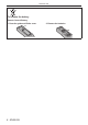
Read this first! To remove the battery Remote Control Battery 1. Press the guide and lift the cover. (i) 8 - ENGLISH (ii) 2. Remove the batteries.
rrTrademarks • Microsoft®, Windows®, Windows Vista®, and Internet Explorer® are the registered trademarks or trademarks of Microsoft Corporation in the United States and/or other countries. • Mac, Mac OS, Mac OSX, and Safari are the trademarks of Apple Inc. registered in the United States and other countries. • PJLinkTM is a trademark or pending trademark in Japan, the United States, and other countries and regions.
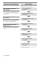
Features of the Projector Quick Steps For details, see the corresponding pages. High luminance & High color reproducibility ▶▶The unique optical and lamp drive systems achieve a high luminance and high color reproducibility. Easy setup and improved serviceability ▶▶Extensive lineup of optional lenses allow more flexible setup of the projector. Improved cost performance in maintenance fee ▶▶The long life filter reduces maintenance costs. 1. Set up the projector. (x page 26) c 2.
Contents Contents Read this first!.............................................2 Chapter 1 Preparation Precautions for use.................................................. 14 Cautions when transporting................................... 14 Cautions when installing........................................ 14 Security................................................................. 15 Disposal................................................................. 16 Cautions on use...............................
Contents [DISPLAY OPTION] menu......................................... 68 [COLOR MATCHING]............................................ 68 [COLOR CORRECTION]...................................... 69 [CONTRAST MODE]............................................. 69 [SCREEN SETTING]............................................. 69 [AUTO SIGNAL].................................................... 70 [AUTO SETUP]..................................................... 70 [RGB IN]......................................
Chapter 1 Preparation This chapter describes things you need to know or check before using the projector.
Chapter 1 Preparation — Precautions for use Precautions for use Cautions when transporting ffThe projection lens is susceptible to effects from vibration or impact. Make sure to remove the projection lens when transporting. Also, use a protection cover or the like to prevent dust from affecting the projection lens or the set. ffWhen transporting the projector, hold it securely by its bottom and avoid excessive vibration and impacts. They may damage the internal parts and result in malfunctions.
Chapter 1 Preparation — Precautions for use ffUse the adjustable feet only for the floor standing installation and for adjusting the angle. Using it for other purposes may damage the set. Screw holes for ceiling mount (M6) Adjustable feet Fig. 1 The positions of screw holes for ceiling mount and adjustable feet ffDo not stack projectors on top of each other. ffDo not use the projector tilted at an angle that exceeds ± 15° from the horizontal plane.
Chapter 1 Preparation — Precautions for use Disposal To dispose of the product, ask your local authorities or dealer for correct methods of disposal. The lamp contains mercury. When disposing of used lamp units, contact your local authorities or dealer for correct methods of disposal. Cautions on use rrTo get a good picture quality In order to view a beautiful image in higher contrast, prepare an appropriate environment.
Chapter 1 Preparation — Precautions for use Accessories Make sure that the following accessories are provided with your projector. Numbers enclosed in < > show the number of accessories.
Chapter 1 Preparation — Precautions for use Optional accessories Optional accessories (product name) Model No.
Chapter 1 Preparation — Start-up display Start-up display The initial setting screen is displayed when the projector is switched on for the first time after purchase as well as when [INITIALIZE] – [ALL USER DATA] (x page 84) is executed. Set them in accordance with circumstances. In other occasions, you can change the settings by menu operations. Note ff When the projector is used for the first time, you may be required to adjust the focus, zoom, and shift to display the menu screen clearly.
Chapter 1 Preparation — About your projector About your projector Remote control Front Top 1 16 2 3 4 5 11 6 12 7 8 Bottom 13 14 17 9 10 1 15 Power standby button Sets the projector to the state where the projector is switched off (standby mode) when the switch on the projector is set to and in projection mode. 2 Power on button Starts projection when the switch on the projector is set to and the power is switched off (standby mode).
Chapter 1 Preparation — About your projector Projector body Front 1 2 3 Side 4 5 13 14 13 Front 6 7 8 15 16 17 6 Rear Front 9 10 11 12 Bottom 13 19 13 18 13 8 Projection lens (for models with attached lenses only) 9 Air exhaust port 10 Lamp unit cover (x page 114) 11 Control panel (x page 22) 12 Remote control signal receiver (rear) 13 Air intake port 14 Connecting terminals (x page 22) 15 switch Turns on/off the main power.
Chapter 1 Preparation — About your projector rrControl panel 9 1 2 10 3 4 11 5 6 7 8 12 13 14 9 1 Power standby button Sets the projector to the standby mode when the switch on the projector is set to . 2 Power on button Starts projection when the switch on the projector is set to when the power is switched off (standby mode). 3
Chapter 1 Preparation — Using the remote control Using the remote control Inserting and removing the batteries 1) Open the cover. (i) 2) Insert the batteries and close the cover (insert the m side first). (ii) ffWhen removing the batteries, perform the steps in reverse order.
Chapter 1 Preparation — Using the remote control Connecting to the projector with a cable When you use the system with multiple projectors, configure the units as in the following figure. Use a commercial M3 stereo mini jack cable and connect the other devices to the / terminals of the projector. The remote control is effective even in places where an obstacle stands in the light path or where devices are susceptible to outside light.
Chapter 2 Getting Started This chapter describes about things you need to do before using the projector such as the setup and connections.
Chapter 2 Getting Started — Setting up Setting up Projection method You can use the projector with any of the following four projection methods. Select the appropriate method depending on the environment.
Chapter 2 Getting Started — Setting up Screen size and throw distance Refer to the following figures and table describing projection distances to install the projector. Image size and image position can be adjusted in accordance with the screen size and screen position.
Chapter 2 Getting Started — Setting up Projection distance per projection lens For PT-DW740E rrWhen the screen aspect is 16:10 (unit: m) (The dimensions of the following table contain slight error.) Optional lens Lens type Standard zoom lens Fixedfocus lens Projection lens Model No. ― ET-DLE055 Throw ratio*1 1.8 – 2.5:1 0.8:1 Projection screen size Ultra-short focus zoom lens Short focus zoom Medium focus zoom lens lens ET-DLE080/ ET-DLE085 ET-DLE150 ET-DLE250 0.8 – 1.0:1 1.4 – 2.0:1 2.
Chapter 2 Getting Started — Setting up rrWhen the screen aspect is 16:9 (unit: m) (The dimensions of the following table contain slight error.) Optional lens Lens type Standard zoom lens Fixedfocus lens Projection lens Model No. ― ET-DLE055 1.8 – 2.5:1 0.8:1 Throw ratio *1 Projection screen size Ultra-short focus zoom lens Short focus zoom Medium focus zoom lens lens ET-DLE080/ ET-DLE085 ET-DLE150 ET-DLE250 0.8 – 1.0:1 1.4 – 2.0:1 2.4 – 3.
Chapter 2 Getting Started — Setting up rrWhen the screen aspect is 4:3 (unit: m) (The dimensions of the following table contain slight error.) Optional lens Lens type Standard zoom lens Fixedfocus lens Projection lens Model No. ― ET-DLE055 2.2 – 3.0:1 1.0:1 Throw ratio *1 Projection screen size Ultra-short focus zoom lens Short focus zoom Medium focus zoom lens lens ET-DLE080/ ET-DLE085 ET-DLE150 ET-DLE250 1.0 – 1.2:1 1.6 – 2.4:1 2.9 – 4.
Chapter 2 Getting Started — Setting up For PT-DX810E rrWhen the screen aspect is 4:3 (unit: m) (The dimensions of the following table contain slight error.) Optional lens Lens type Standard zoom lens Fixedfocus lens Projection lens Model No. ― ET-DLE055 Throw ratio*1 1.8 – 2.5:1 0.8:1 Projection screen size Ultra-short focus zoom lens Short focus zoom Medium focus zoom lens lens ET-DLE080/ ET-DLE085 ET-DLE150 ET-DLE250 0.8 – 1.0:1 1.3 – 2.0:1 2.4 – 3.
Chapter 2 Getting Started — Setting up rrWhen the screen aspect is 16:9 (unit: m) (The dimensions of the following table contain slight error.) Optional lens Lens type Standard zoom lens Fixedfocus lens Projection lens Model No. ― ET-DLE055 1.8 – 2.5:1 0.8:1 Throw ratio *1 Projection screen size Ultra-short focus zoom lens Short focus zoom Medium focus zoom lens lens ET-DLE080/ ET-DLE085 ET-DLE150 ET-DLE250 0.8 – 1.0:1 1.3 – 2.0:1 2.4 – 3.
Chapter 2 Getting Started — Setting up Projection distance formulas by projection lens To use a screen size not listed in this manual, check the screen size SD and use the following formula to calculate projection distance. The unit of the calculation result is m. For PT-DW740E Lens type Projection lens Model No.
Chapter 2 Getting Started — Setting up Lens type Ultra-short focus zoom lens Projection lens Model No. Aspect ratio 4:3 ET-DLE080/ET-DLE085 16:9 4:3 Short focus zoom lens ET-DLE150 16:9 4:3 Medium focus zoom lens ET-DLE250 16:9 4:3 Long focus zoom lens ET-DLE350 16:9 4:3 Ultra-long focus zoom lens ET-DLE450 16:9 Projection distance (L) formula Min. (LW) L = 0.6693 x SD (m) – 0.0471 Max. (LT) L = 0.8307 x SD (m) – 0.0442 Min. (LW) L = 0.7323 x SD (m) – 0.0471 Max. (LT) L = 0.
Chapter 2 Getting Started — Removing/attaching the projection lens Removing/attaching the projection lens Attach and remove the projection lens in the same way as a standard zoom lens and optional accessories. Move the projection lens to the home position before replacing or removing the lens (x page 46). Attention ffReplace the projection lens after turning off the power of the projector. ffDo not touch the lens signal receiver. Dust or dirt may cause defective contact.
Chapter 2 Getting Started — Removing/attaching the projection lens 3) Attach the projection lens cover aligning the marking (groove *1) with the tip of the arrow on the projector (*2), and secure the projection lens cover by turning it until groove *1 aligns with the *3 P marking. (i) Projection lens cover *3 *2 (ii) *1 Attention ffTurn the projection lens counterclockwise to confirm that it does not come out.
Chapter 2 Getting Started — Connections Connections Before connecting to the projector ffBefore connecting, carefully read the operating instructions for the external device to be connected. ffTurn off the power of all devices before connecting cables. ffAcquire any connection cable necessary to connect the external device to the system that is either not supplied with the device or not available as an option.
Chapter 2 Getting Started — Connections Connecting example: AV equipment DVD player with attached HDMI terminal (HDCP) VCR (with built-in TBC) or Blu-ray disc player Attention ffAlways use one of the following when connecting a VCR. ggA VCR with built-in time base corrector (TBC) ggA time base corrector (TBC) between the projector and the VCR ffIf nonstandard burst signals are connected, the image may be distorted. In such case, connect the time base corrector (TBC) between the projector and the VCR.
Chapter 2 Getting Started — Connections ffThe terminal of the projector can be connected to an external device with a DVI-D terminal by using an HDMI/DVI conversion cable, but some devices may not project the image properly or function properly. ffThe terminal supports single link only. ffFor signals that the projector can project, refer to “List of compatible signals” (x page 125).
Chapter 3 Basic Operation This chapter describes basic operations to start with.
Chapter 3 Basic Operation — Switching on/off the projector Switching on/off the projector Connecting the power cord Make sure that the supplied power cord cover is securely fixed to the projector to prevent removal of the power cord. Confirm that the switch is on the side before connecting the power cord. For details of power cord handling, refer to “Read this first!” (x pages 2 to 8).
Chapter 3 Basic Operation — Switching on/off the projector Power indicator Displays the status of the power. Check the status of the power indicator before operating the projector. Power indicator Indicator status Status No illumination or flashing The main power is switched off. Red Lit The power is switched off. (Standby mode.) Projection will start if the power on button is pressed.
Chapter 3 Basic Operation — Switching on/off the projector or higher, turn off the main power, and then turn on the power again. ffIf [PROJECTOR SETUP] → [STANDBY MODE] (x page 78) is set to [ECO] on the menu, there may be a 10 second display lag when the power is turned on compared to when the setting is [NORMAL].
Chapter 3 Basic Operation — Switching on/off the projector 3) Wait until the power indicator of the projector lights in red (and the fan stops) for approximately 170 seconds. 4) Press the side of the switch to turn off the power. Note ffDo not turn on the power and project images immediately after turning the projector off. Turning on the power while the lamp is still hot may shorten the lamp life.
Chapter 3 Basic Operation — Projecting Projecting Check the projection lens attachment (x page 35), external device connection (x page 37) and power cord connection (x page 41), and then switch on the power (x page 42) to start projecting. Select the video for projection, and adjust appearance of the projected image. Selecting the input signal Select an input signal. 1) Press the input selection (, , ,
Chapter 3 Basic Operation — Projecting Moving the lens to the home position Perform the following procedure to move the lens to the home position. 1) Press the button on the control panel or the button on the remote control for at least three seconds. 2) While the [HOME POSITION] menu is displayed (for approximately five seconds), press the button.
Chapter 3 Basic Operation — Remote control operation Remote control operation Using the shutter function If the projector is not used for a certain period of time during the meeting intermission, for example, it is possible to turn off the image temporarily. button 1) Press the button. ffThe image disappears. ffThis operation can be also performed using the button on the control panel. 2) Press the button again. ffThe image is displayed.
Chapter 3 Basic Operation — Remote control operation Switching the input The input for projection can be switched. button 1) Press the input selection (, , ,
Chapter 3 Basic Operation — Remote control operation 1) Press the button. ff[COMPLETE] is displayed when it has completed without any problem. ffThis operation can be also performed using the button on the control panel. Note ffThe CLOCK PHASE may shift even if it has completed without any incident. In such cases, adjust with the [POSITION] menu → [CLOCK PHASE] (x page 62).
Chapter 4 Settings This chapter describes the settings and adjustments you can make using the on-screen menu.
Chapter 4 Settings — Menu navigation Menu navigation The on-screen menu (Menu) is used to perform various settings and adjustments of the projector. Navigating through the menu Operating procedure button 1) Press the
Chapter 4 Settings — Menu navigation 1) Press the button on the remote control. &2175$67 $'-867 Note ffYou cannot reset all the settings to the factory default at once. ffTo reset all the settings adjusted in the sub-menu item to the factory default at a time, perform initialization from the [PROJECTOR SETUP] menu → [INITIALIZE] (x page 84). ffSome menu items cannot be reset by pressing the button. Adjust each item manually.
Chapter 4 Settings — Menu navigation Sub-menu item Factory default Page [OFF] 57 [SHARPNESS] [6] 58 [NOISE REDUCTION] [1] 58 [SYSTEM DAYLIGHT VIEW] * [AI] * [ON] [SYSTEM SELECTOR] 58 [YPBPR] 59 Factory default Page ― 60 * * Depends on the signal input. Note ffThe factory default settings may vary depending on the picture mode. [POSITION] Sub-menu item [SHIFT] [ASPECT] [DEFAULT] 60 ― 61 [16] 62 ― 63 * [ZOOM] [CLOCK PHASE] [KEYSTONE] * Depends on the signal input.
Chapter 4 Settings — Menu navigation [PROJECTOR SETUP] Sub-menu item [PROJECTOR ID] Factory default Page [ALL] 75 [PROJECTION METHOD] [FRONT/FLOOR] 75 [COOLING CONDITION] [FLOOR SETTING] 76 [HIGH ALTITUDE MODE] [OFF] 76 [DUAL] 76 [LAMP RELAY] [OFF] 77 [LAMP POWER] [NORMAL] 77 [STANDBY MODE] [NORMAL] 78 [OFF] 78 [LAST USED] 79 ― 80 [DEFAULT] 81 [LAMP SELECT] [SCHEDULE] [STARTUP INPUT SELECT] [RS-232C] [REMOTE2 MODE] [STATUS] ― 81 [DISABLE] 82 [FUNCTION BUTTON] ― 82
Chapter 4 Settings — [PICTURE] menu [PICTURE] menu Select [PICTURE] from the main menu, and select the item from the sub-menu. Refer to “Navigating through the menu” (x page 51) for the operation of the menu screen. ffAfter selecting the item, press asqw to adjust. [PICTURE MODE] You can switch to the desired picture mode suitable for the image source and the environment in which the projector is used. 1) Press as to select [PICTURE MODE]. 3) Press qw to switch [PICTURE MODE].
Chapter 4 Settings — [PICTURE] menu 3) Press qw to adjust the level. rrOperations and adjustment range Operation Adjustment Press w. Increases the brightness of the dark (black) parts of the screen. Press q. Reduces the brightness of the dark (black) parts of the screen. Range -31 - +31 [COLOR] You can adjust the color saturation of the projected image. 1) Press as to select [COLOR]. 2) Press qw or the button. ffThe [COLOR] individual adjustment screen is displayed.
Chapter 4 Settings — [PICTURE] menu 6) Press the button. 8) Press the button. ffThe [WHITE BALANCE] screen is displayed. ffThe [WHITE BALANCE HIGH] screen or the [WHITE BALANCE LOW] screen is displayed. 7) Press as to select [WHITE BALANCE HIGH] 9) Press as to select [RED], [GREEN], or [BLUE]. or [WHITE BALANCE LOW]. 10) Press qw to adjust the level. rrAdjustment details Item Operation [RED] [GREEN] [BLUE] Press w. Adjustment Range Deepens red. Press q. Weakens red. Press w.
Chapter 4 Settings — [PICTURE] menu 2) Press qw or the button. 3) Press qw to switch [SYSTEM DAYLIGHT VIEW]. ffThe [SYSTEM DAYLIGHT VIEW] individual adjustment screen is displayed. ffThe setting will change among [OFF], [1], [2] and [3] each time you press the button. rr[SYSTEM DAYLIGHT VIEW] [OFF] No correction. [1] Corrects the image to weaken vividness. [2] Corrects the image to medium vividness. [3] Corrects the image to high vividness.
Chapter 4 Settings — [PICTURE] menu [SYSTEM SELECTOR] The projector will automatically detect the input signal, but you can set the system method manually when an unstable signal is input. Set the system method matching the input signal. 1) Press as to select [SYSTEM SELECTOR]. 3) Press as to select a system format. 2) Press the button. 4) Press the button.
Chapter 4 Settings — [POSITION] menu [POSITION] menu Select [POSITION] from the main menu, and select the item from the sub-menu. Refer to “Navigating through the menu” (x page 51) for the operation of the menu screen. ffAfter selecting the item, press asqw to adjust. [SHIFT] You can move the image position vertically or horizontally if the image position projected on the screen is shifted even when the relative position of the projector and the screen is installed correctly.
Chapter 4 Settings — [POSITION] menu rr[ASPECT] [DEFAULT] Pictures are displayed without changing the aspect ratio of the input signals. [VID AUTO] The projector identifies the video ID (VID) embedded in the image signals and displays the image by automatically switching the screen sizes between 4:3 and 16:9. This function is effective for VIDEO/S-VIDEO (NTSC) signals.
Chapter 4 Settings — [POSITION] menu Note ffWhen [ASPECT] is set to [THROUGH], [ZOOM] is not displayed. When [ASPECT] is set to [DEFAULT] 1) Press as to select [ZOOM]. 5) Press as to select [INTERLOCKED]. 2) Press the button. 6) Press qw to switch [INTERLOCKED]. ffThe [ZOOM] screen is displayed. 7) Press as to select [VERTICAL] or 3) Press as to select [MODE]. [HORIZONTAL]. ffSelect [BOTH] when [ON] is selected. 4) Press qw to switch [MODE]. 8) Press qw to adjust.
Chapter 4 Settings — [POSITION] menu [KEYSTONE] You can correct the trapezoidal distortion that occurs when the projector is installed tilted or when the screen is tilted. 1) Press as to select [KEYSTONE]. 3) Press as to select the item to adjust. 2) Press the button. 4) Press qw to adjust. ffThe [KEYSTONE] screen is displayed. rrAdjustment details [KEYSTONE] [SUB KEYSTONE] [LINEARITY] Note ffThe menu or logo may run off the screen when various adjustments are performed with [KEYSTONE].
Chapter 4 Settings — [ADVANCED MENU] menu [ADVANCED MENU] menu Select [ADVANCED MENU] from the main menu, and select the item from the sub-menu. Refer to “Navigating through the menu” (x page 51) for the operation of the menu screen. ffAfter selecting the item, press asqw to adjust.
Chapter 4 Settings — [ADVANCED MENU] menu Blanking correction Left side of the screen Right side of the screen Item Operation Adjustment Press w. The blanking zone moves to the right. Press q. The blanking zone moves to the left. Range [LEFT] Press q. The blanking zone moves to the right. Press w. The blanking zone moves to the left.
Chapter 4 Settings — [ADVANCED MENU] menu 7) Press qw to switch [ON]. ffA marker for image position adjustment is displayed. 8) Press as to select [START] or [WIDTH], then press qw to adjust starting point and correction width. ffThe green line is the starting point of edge blending adjusted with [START]. The red line is the ending point of edge blending adjusted with [WIDTH]. The position where the red and green lines overlap for the sets to join will be the optimal point.
Chapter 4 Settings — [DISPLAY LANGUAGE] menu [DISPLAY LANGUAGE] menu Select [DISPLAY LANGUAGE] from the main menu, and display the sub-menu. Refer to “Navigating through the menu” (x page 51) for the operation of the menu screen. ffPress as to select a language, and press the button to set. Changing the display language You can select the language of the on-screen display. DISPLAY LANGUAGE ● 日本語 ffVarious menus, settings, adjustment screens, control button names, etc.
Chapter 4 Settings — [DISPLAY OPTION] menu [DISPLAY OPTION] menu Select [DISPLAY OPTION] from the main menu, and select the item from the sub-menu. Refer to “Navigating through the menu” (x page 51) for the operation of the menu screen. ffAfter selecting the item, press asqw to set. [COLOR MATCHING] You can correct the color difference between the sets when multiple sets are to be used simultaneously. To adjust the color matching as desired 1) Press as to select [COLOR MATCHING].
Chapter 4 Settings — [DISPLAY OPTION] menu 5) Press the button. 9) Press as to select [TARGET DATA]. ffThe [MEASURED DATA] screen is displayed. 10) Press the button. 6) Measure the current luminance (Y) and the ffThe [TARGET DATA] screen is displayed. chromaticity coordinates (x, y) using the colorimeter. 11) Press as to select a color, and press qw to 7) Press as to select a color, then press qw to adjust the value. input coordinates for desired colors.
Chapter 4 Settings — [DISPLAY OPTION] menu [AUTO SIGNAL] Set automatic execution of auto setup. The screen display position or signal level can be adjusted automatically without pressing the button on the remote control on each occasion if you input unregistered signals frequently at meetings, etc. 1) Press as to select [AUTO SIGNAL]. 2) Press qw to switch [AUTO SIGNAL]. ffThe setting will change between [OFF] and [ON] each time you press the button.
Chapter 4 Settings — [DISPLAY OPTION] menu 6) Press qw to switch [DVI SIGNAL LEVEL]. ffThe setting will change between [0-255:PC] and [16-235] each time you press the button. rr[DVI EDID] [EDID3] Switch between fine settings for a moving image and for a still image. [EDID1] Select mainly when an external device that outputs movie-type image signals (such as a blu-ray disk player) is connected to the terminal.
Chapter 4 Settings — [DISPLAY OPTION] menu rr[ON-SCREEN DISPLAY] [OSD POSITION] [OSD DESIGN] [OSD MEMORY] [INPUT GUIDE] [WARNING MESSAGE] [2] Set the position of the menu screen (OSD) to the center left of the screen. [3] Set the position of the menu screen (OSD) to the bottom left of the screen. [4] Set the position of the menu screen (OSD) to the top center of the screen. [5] Set the position of the menu screen (OSD) to the center of the screen.
Chapter 4 Settings — [DISPLAY OPTION] menu Note ffThe startup logo will disappear in approximately 15 seconds. ffTo create the image for [USER LOGO], “Logo Transfer Software” included in the supplied CD-ROM is required. [SHUTTER SETTING] Set the opening and closing status of the shutter for when projection begins by switching on the projector, and for when the projector is switched off. To set [STARTUP] 1) Press as to select [SHUTTER SETTING]. 3) Press as to select [STARTUP].
Chapter 4 Settings — [DISPLAY OPTION] menu rrSetting the two window display [VIDEO] [S-VIDEO] Displays images of [VIDEO] input on the right screen (Input B). Displays images of [S-VIDEO] input on the right screen (Input B). [RGB1] Displays images of [RGB1] input on the right screen (Input B). [RGB2] Displays images of [RGB2] input on the right screen (Input B). [DVI-D] Displays images of [DVI-D] input on the right screen (Input B).
Chapter 4 Settings — [PROJECTOR SETUP] menu [PROJECTOR SETUP] menu Select [PROJECTOR SETUP] from the main menu, and select the item from the sub-menu. Refer to “Navigating through the menu” (x page 51) for the operation of the menu screen. ffAfter selecting the item, press asqw to set. [PROJECTOR ID] The projector has an ID number setting function that can be used when multiple projectors are used side by side to enable simultaneous control or individual control via one remote control.
Chapter 4 Settings — [PROJECTOR SETUP] menu [COOLING CONDITION] Change the fan control depending on the direction of projection. Set [COOLING CONDITION] correctly in accordance with the direction of projection referring to the following figure. It may shorten the life of the lamp if used in incorrect setting. [VERTICAL UP SETTING] [FLOOR SETTING] 30° 30° [CEILING SETTING] 30° 30° [VERTICAL DOWN SETTING] :Projection direction 1) Press as to select [COOLING CONDITION]. 2) Press the button.
Chapter 4 Settings — [PROJECTOR SETUP] menu operating time of either of them exceeds 2000 hours (when [LAMP POWER] is set to [NORMAL]), only the other lamp will light. However, if both lamps do not light, or the cumulative operating time of both of them exceeds 2000 hours (when [LAMP POWER] is set to [NORMAL]), the projector will go into standby. ffThe font colors of the items indicate the status.
Chapter 4 Settings — [PROJECTOR SETUP] menu Note ffWhen [ECO] is set, the power consumption and operation sound can be reduced while the lamp life can be increased. [STANDBY MODE] Set the power consumption during the standby. 1) Press as to select [STANDBY MODE]. 2) Press qw to switch [STANDBY MODE]. ffThe setting will change between [NORMAL] and [ECO] each time you press the button. rr[STANDBY MODE] [NORMAL] [ECO] Normally use this setting.
Chapter 4 Settings — [PROJECTOR SETUP] menu 9) Press qw to switch [COMMAND]. 11) Press as to select a command. ffThe setting will change among [POWER ON], [STANDBY], [SHUTTER]*1, [INPUT]*1, [LAMP SELECT]*1, [LAMP POWER]*1 and [SIDE BY SIDE]*1*2 each time you press the button. *1 The details set in step 11) are displayed. *2 Only for PT-DW740E 10) Press the button.
Chapter 4 [S-VIDEO] Settings — [PROJECTOR SETUP] menu Sets the input to be projected when the projector is switched on to S-VIDEO. [DVI-D] Sets the input to be projected when the projector is switched on to DVI-D. [HDMI] Sets the input to be projected when the projector is switched on to HDMI. [RS-232C] Set the communication conditions of the / terminal. To set the communication condition of the terminal 1) Press as to select [RS-232C].
Chapter 4 Settings — [PROJECTOR SETUP] menu 6) Press qw to switch [GROUP]. 8) Press qw to switch [RESPONSE(ID GROUP)]. ffThe setting will change among [A] to [Z] each time you press the button. ffThe setting will change between [ON] and [OFF] each time you press the button. 7) Press as to select [RESPONSE(ID GROUP)]. rr[RESPONSE(ID ALL)] [ON] Returns the response when the ID setting is ALL. [OFF] Does not return the response when the ID setting is ALL.
Chapter 4 Settings — [PROJECTOR SETUP] menu [LAMP1 SERIAL NUMBER] Displays the serial number of the lamp 1. [LAMP2 SERIAL NUMBER] Displays the serial number of the lamp 2. [MAIN VERSION] Displays the main version of the firmware of the projector. [SUB VERSION] Displays the sub version of the firmware of the projector. [NETWORK VERSION] [POWER ON TIMES] [ON COUNT] Displays the network version of the projector. Displays the number of times the power is turned on.
Chapter 4 [SYSTEM DAYLIGHT VIEW] [FREEZE] [SIDE BY SIDE]* [ASPECT] Settings — [PROJECTOR SETUP] menu Switches the [SYSTEM DAYLIGHT VIEW] setting. (x page 57) Temporarily freezes video to be a still image. (x page 73) Switches to the two window display. (x page 73) Switches the aspect setting. (x page 60) * Only for PT-DW740E [DATE AND TIME] Set the time zone, date, and time of the built-in clock of the projector. To set time zone 1) Press as to select [DATE AND TIME].
Chapter 4 Settings — [PROJECTOR SETUP] menu [LOAD ALL USER DATA] Load the various setting values saved as a backup in the built-in memory of the projector. 1) Press as to select [LOAD ALL USER DATA]. 2) Press the button. ffThe [SECURITY PASSWORD] screen is displayed. 3) Enter a security password and press the button. 4) When the confirmation is displayed, select [OK] or [CANCEL], and press the button.
Chapter 4 Settings — [TEST PATTERN] menu [TEST PATTERN] menu Select [TEST PATTERN] from the main menu. Refer to “Navigating through the menu” (x page 51) for the operation of the menu screen. ffPress qw to switch. [TEST PATTERN] Displays the test pattern built-in to the projector. Settings of position, size, and other factors will not be reflected in test patterns. Make sure to display the input signal before performing various adjustments. 1) Press qw to switch [TEST PATTERN].
Chapter 4 Settings — [SIGNAL LIST] menu [SIGNAL LIST] menu Select [SIGNAL LIST] from the main menu. Refer to “Navigating through the menu” (x page 51) for the operation of the menu screen. rrRegistered signal status ffA name can be set for each sub memory (x page 87). ffMemory number: A1 (1-2) Sub memory number When the address number (A1, A2, ...
Chapter 4 Settings — [SIGNAL LIST] menu Note ffA signal can also be deleted from [ENTRY SIGNAL DELETE] on the [REGISTERED SIGNAL SETUP] screen. Protecting the registered data Registered signals can be protected. 1) Press asqw to select the signal to protect. 4) Press as to select [LOCK]. 2) Press the button. 5) Press qw to switch [LOCK]. ffThe [REGISTERED SIGNAL STATUS] screen is displayed. 3) Press the button.
Chapter 4 Settings — [SIGNAL LIST] menu To register the current settings to the list 1) Press qw on the normal screen (when the menu is not displayed). ffThe sub memory registration screen is displayed if the sub memory is not registered. Proceed to Step 3). ffA list of sub memories registered to the signal currently input is displayed. ffWhen [SUB MEMORY] is selected with [PROJECTOR SETUP] → [FUNCTION BUTTON] on the menu, the button can be used instead of qw.
Chapter 4 Settings — [SECURITY] menu [SECURITY] menu Select [SECURITY] from the main menu, and select the item from the sub-menu. Refer to “Navigating through the menu” (x page 51) for the operation of the menu screen. ffWhen the projector is used for the first time Initial password: Press awsqawsq in order, and press the button. ffAfter selecting the item, press asqw to set.
Chapter 4 Settings — [SECURITY] menu 1) Press as to select [DISPLAY SETTING]. 2) Press qw to switch [DISPLAY SETTING]. ffThe setting will change among [OFF], [TEXT], and[USER LOGO] each time you press the button. rr[DISPLAY SETTING] [OFF] The text display is disabled. [TEXT] The text display is enabled. [USER LOGO] The picture registered by the user is projected. Note ffTo create the image for [USER LOGO], “Logo Transfer Software” included in the supplied CD-ROM is required.
Chapter 4 Settings — [SECURITY] menu 3) Press as to select [CONTROL PANEL] or 5) Press as to select an item, and press the 4) Press the button. 6) When the confirmation is displayed, select [OK] [REMOTE CONTROL]. ffThe [CONTROL PANEL] screen or the [REMOTE CONTROL] screen is displayed. button. or [CANCEL], and press the button. rr[CONTROL PANEL] and [REMOTE CONTROL] ffYou can set the limitation on the control from the control panel and remote control.
Chapter 4 Settings — [NETWORK] menu [NETWORK] menu Select [NETWORK] from the main menu, and select the item from the sub-menu. Refer to “Navigating through the menu” (x page 51) for the operation of the menu screen. ffAfter selecting the item, press asqw to set. [NETWORK SETUP] Perform the initial setting of the network before using the network function. 1) Press as to select [NETWORK SETUP]. 2) Press the button. ffThe [NETWORK SETUP] screen is displayed.
Chapter 4 Settings — [NETWORK] menu rr[NETWORK CONTROL] [WEB CONTROL] [PJLink CONTROL] [COMMAND CONTROL] [COMMAND PORT] [CRESTRON RoomView] [AMX D.D.] [STORE] Set to [ON] to control with the Web browser. Set to [ON] to control with the PJLink protocol. Set to [ON] to control with the / terminal control command format (x page 123). Refer to “Control commands via LAN” (x page 119). Set the port number used for command control. Set to [ON] to control with RoomView of Crestron.
Chapter 4 Settings — [NETWORK] menu Name and function of network function parts 1 2 3 1 LAN10/100 lamp (yellow) Lights on when connected to the 100BASE-TX. 2 terminal (10BASE-T/100BASE-TX) Used to connect the LAN cable here. 3 LAN LINK/ACT lamp (green) Lights on when connected. Flashes when transmitting/receiving data. Attention ffConnect the LAN to indoor devices. Accessing from the Web browser 1) Start up the Web browser on the computer.
Chapter 4 Settings — [NETWORK] menu Descriptions of items (1) (2) (3) (4) (5) (6) 1 Page tab Switches pages by clicking it. 4 [Detailed set up] The [Detailed set up] page is displayed by clicking this item. 2 [Status] The status of the projector is displayed by clicking this item. 5 [Change password] The [Change password] page is displayed by clicking this item. 3 [Projector control] The [Projector control] page is displayed by clicking this item.
Chapter 4 Settings — [NETWORK] menu Error information page When [Error (Detail)] is displayed in the self-diagnosis display of the [Projector status] screen, click it to display the error details. ffThe projector may go into the standby status to protect the projector depending on the contents of the error. [OK]: operating properly [FAILED]: a problem occurred [WARNING]: warning rrProblem occurrence [FAILED] Parameter Description [MAIN CPU BUS] There is a problem with the microcomputer circuitry.
Chapter 4 Settings — [NETWORK] menu [Network status] page Click [Status] → [Network status]. The current network setting status is displayed. [Access error log] page Click [Status] → [Access error log]. The error log on the WEB server is displayed such as access to the pages that do not exist or access with unauthorized user names or passwords. [Access log] page Click [Status] → [Access log]. The log such as user name accessed to the WEB control page, accessed IP address, and accessed time is displayed.
Chapter 4 Settings — [NETWORK] menu [Basic control] page Click [Projector control] → [Basic control]. (1) (2) (3) (4) (5) (6) 1 [POWER] Switches the power on/off. 4 [SYSTEM] Switches the system method. 2 [SHUTTER] Switches between use or not use of the shutter function. 5 3 [OSD] Switches between on (display)/off (no display) of the on-screen display function. On-screen display of the projector Displays the same content as the on-screen display of the projector.
Chapter 4 Settings — [NETWORK] menu ffThe following setting change screen is displayed by pressing the [Change] button. (1) (2) (3) (4) (5) (6) (7) (8) 1 [PROJECTOR NAME] Enter the name of the projector. Also enter the host name if it is required when using a DHCP server, etc. 2 [DHCP ON]/[DHCP OFF] To enable the DHCP client function, set to [DHCP ON]. 3 [IP ADDRESS] Enter the IP address when not using a DHCP server. 4 [SUBNET MASK] Enter the subnet mask when not using a DHCP server.
Chapter 4 Settings — [NETWORK] menu Note ffThe replacement of the battery inside the projector is required when the time goes out of alignment right after correcting the time. Please consult your dealer. [Ping test] page You can check whether the network is connected to the E-mail server, POP server, DNS server, etc. Click [Detailed set up] → [Ping test]. (1) (2) (3) (4) 1 [Input IP address] Enter the IP address of the server to be tested. 2 [Submit] Executes the connection test.
Chapter 4 Settings — [NETWORK] menu [E-mail set up] page You can send E-mail to an E-mail address (maximum two addresses) set in advance when a problem occurs or the cumulative operating time of a lamp reaches a set value. Click [Detailed set up] → [E-mail set up]. (1) (2) (3) (4) (5) (6) 1 [ENABLE] Select [Enable] to use the E-mail function. 2 [SMTP SERVER NAME] Enter the IP address or the server name of the E-mail server (SMTP). To enter the server name, the setup of the DNS server is required.
Chapter 4 Settings — [NETWORK] menu (9) (10) (11) 9 [LAMP2 RUNTIME]: An E-mail message is sent when the remaining lamp on time for the lamp 2 has reached the value set at the right field. [INTAKE AIR TEMPERATURE]: An E-mail message is sent when the air intake temperature has reached the value set at the above field. [PERIODIC REPORT]: Place a check mark on this to send E-mail to the second E-mail address periodically. It will be sent on the days and time with the check mark.
Chapter 4 Settings — [NETWORK] menu Contents of mail sent Example of E-mail sent when E-mail is set The following E-mail is sent when the E-mail settings have been established.
Chapter 4 Settings — [NETWORK] menu Example of the E-mail sent for an error The following E-mail is sent when an error has occurred. === Panasonic projector report(CONFIGURE) === Projector Type : DW740 Serial No : SH1234567 ----- check system ----MAIN CPU BUS [ OK ] FAN [ OK ] INTAKE AIR TEMPERATURE [ OK ] OPTICS MODULE TEMPERATURE [ OK ] AROUND LAMP TEMPERATURE [ OK ] LAMP1 REMAIN TIME [ OK ] LAMP2 REMAIN TIME [ OK ] LAMP1 STATUS [ OK ] LAMP2 STATUS [ OK ] SHUTTER [ OK ] INTAKE AIR TEMP.
Chapter 4 Settings — [NETWORK] menu [Administrator] account (1) (2) (3) (4) (5) (6) (7) 5 [Current][User name] Enter the user name before the change. [New][Password] Enter the desired new password. (Up to 16 characters in single byte) 6 3 [Current][Password] Enter the current password. [New][Password(Retype)] Enter the desired new password again. 7 4 [New][User name] Enter the desired new user name. (Up to 16 characters in single byte) [OK] Determines the change of password.
Chapter 4 Settings — [NETWORK] menu [Change password] (For user rights) Only the change of password is enabled under the user rights. (1) (2) (3) (4) 1 [Old Password] Enter the current password. 3 [Retype] Enter the desired new password again. 2 [New Password] Enter the desired new password. (Up to 16 characters in single byte) 4 [OK] Determines the change of password. Note ffTo change the account of the administrator, you must enter the [Current] [User name] and [Password].
Chapter 4 Settings — [NETWORK] menu [Tools] page Click [Tools] on the control page. 1 2 3 4 5 1 [Control System] Set the information required for communicating with the controller to be connected with the projector. 2 [User Password] Set the user rights password for the RoomView control page. 3 [Admin Password] Set the administrator rights password for the RoomView control page. 4 Network Status Displays the settings of wired LAN. [DHCP] Displays the current setting.
Chapter 4 Settings — [NETWORK] menu [Help] page Click [Help] on the control page. The [Help Desk] window is displayed. 1 1 [Help Desk] Messages can be sent to or received from an administrator who uses Crestron RoomView.
Chapter 5 Maintenance This chapter describes inspection when there are problems, and maintenance methods.
Chapter 5 Maintenance — Lamp/Temperature/Filter indicators Lamp/Temperature/Filter indicators Managing the indicated problems If a problem should occur inside the projector, the lamp indicators // the temperature indicator and the filter indicator will inform you by lighting or flashing. Check the status of the indicators and manage the indicated problems as follows.
Chapter 5 Maintenance — Lamp/Temperature/Filter indicators Temperature indicator Indicator status Flashing in red (1 time) Flashing in red (3 times) Internal temperature is high (standby warning) The cooling fan has stopped.
Chapter 5 Maintenance — Maintenance/replacement Maintenance/replacement Before maintaining/replacing the unit ffMake sure to turn off the power before maintaining or replacing the unit. (x pages 41, 43) ffWhen switching off the projector, make sure to follow the procedures in “Switching off the projector” (x page 43). Maintenance Outer case Wipe off dirt and dust with a soft, dry cloth. ffIf the dirt is persistent, soak the cloth with water and wring it thoroughly before wiping.
Chapter 5 Maintenance — Maintenance/replacement 2) Dry the air filter unit. ffLet the unit naturally dry off in a well-ventilated place where there is little dust and the unit is protected from direct sunlight. ffDo not dry using drying devices such as dryers. ffWhen the air filter unit is dry, proceed to the procedure described in “Attaching the air filter unit” (x page 113). Attaching the air filter unit 1) Attach the air filter unit to the projector.
Chapter 5 Maintenance — Maintenance/replacement Note ff The replacement cycle of the air filter unit varies greatly depending on the usage environment. Lamp unit The lamp unit is a consumable component. Check the lamp usage time in [PROJECTOR SETUP] [STATUS] (x page 81) in the menu and change the lamp periodically. It is recommended that you request a qualified technician to replace the lamp unit. Consult your dealer. Consult your dealer to purchase a replacement lamp unit (Model No.
Chapter 5 Maintenance — Maintenance/replacement 1) Follow the procedures described in “Switching off the projector” (x page 43) to set the switch to , disconnect the power plug from the power outlet, and wait at least one hour, and then check if the lamp unit has cooled down. 2) Remove the lamp unit cover. i) Use a Phillips screwdriver to loosen the lamp unit cover fixing screw (one screw) until it turns freely, and then open the lamp unit cover in the direction of the arrow.
Chapter 5 Maintenance — Troubleshooting Troubleshooting Review the following points. For details, see the corresponding pages. Problems Power does not turn on.
Chapter 6 Appendix This chapter describes specifications and after-sales service for the projector.
Chapter 6 Appendix — Technical information Technical information PJLink protocol The network function of this projector supports the PJLink class 1, and the PJLink protocol can be used to perform projector setting and projector status query operations from a computer. Control commands The following table lists the PJLink protocol commands that can be used to control the projector.
Chapter 6 Appendix — Technical information Control commands via LAN When WEB control administrator rights password is set (Protect mode) Connection method 1) Obtain the IP address and port number (Initial set value = 1024) of the projector and request for a connection to the projector. ffYou can obtain both the IP address and the port number from the menu screen of the projector. IP address Port number Obtain from the main menu → [NETWORK] → [NETWORK STATUS].
Chapter 6 Appendix — Technical information rrError response Error message “ERR1” Undefined control command “ERR2” Out of parameter range “ERR3” Busy state or no-acceptable period “ERR4” Timeout or no-acceptable period “ERR5” Wrong data length “ERRA” Password mismatch Termination symbol (CR) 0x0d 4 bytes 1 byte When WEB control administrator rights password is not set (Non-protect mode) Connection method 1) Obtain the IP address and port number (Initial set value = 1024) of the projector an
Chapter 6 Appendix — Technical information rrError response Error message “ERR1” Undefined control command “ERR2” Out of parameter range “ERR3” Busy state or no-acceptable period “ERR4” Timeout or no-acceptable period “ERR5” Wrong data length “ERRA” Password mismatch Termination symbol (CR) 0x0d 4 bytes 1 byte / terminal The / terminal of the projector conforms with RS-232C so that the projector can be connected to and controlled from a computer
Chapter 6 Appendix — Technical information Sync. method Baud rate Asynchronous 9 600 bps Parity None Character length 8 bit Stop bit 1 bit X parameter None S parameter None Basic format Transmission from the computer starts with STX, then the ID, command, parameter, and ETX are sent in this order. Add parameters according to the details of control.
Chapter 6 Appendix — Technical information Cable specifications 1 NC NC 2 3 Projector ( terminal) 4 NC NC 5 6 1 1 2 2 3 3 4 4 5 NC NC 7 6 Computer (DTE specifications) Projector 1 ( terminal) 7 8 9 NC NC NC NC 1 2 3 NC NC 4 5 6 5 NC NC 6 7 8 8 9 9 Projector 2 ( terminal) 7 8 NC NC 9 Control commands The following table lists the commands that can be used to control the
Chapter 6 Appendix — Technical information terminal It is possible to control the projector remotely (by external contact) from a control panel located away from the projector where remote control signals cannot reach. Use the terminal on the connecting terminals of the projector to connect to the control panel.
Chapter 6 Appendix — Technical information Two window display combination list (PT-DW740E only) RGB1 Still image RGB1 Movie RGB2 Still image RGB2 Movie VIDEO S-VIDEO DVI-D Still image DVI-D Movie HDMI Still image HDMI Movie RGB1 Still image ― ― l l l l l l l l RGB1 Movie ― ― l ― ― ― l ― l ― RGB2 Still image l l ― ― l l l l l l RGB2 Movie l ― ― ― ― ― l ― l ― Input B Input A VIDEO l ― l ― ― ― l ― l ― S-VIDEO l ― l ― ― ― l ― l ― DVI
Chapter 6 Appendix — Technical information Scanning frequency Resolution (Dots) Mode Horizontal (kHz) Vertical (Hz) Dots clock frequency (MHz) Plug and play*3 Format RGB2 DVI-D EDID1 DVI-D EDID2 DVI-D EDID3 HDMI 1125 (1080)/60p 1 920 x 1 080 67.5 60.0 148.5 R/Y/H/D ― l ― l l 1125 (1080)/50p 1 920 x 1 080 56.3 50.0 148.5 R/Y/H/D ― l ― l l VESA400 640 x 400 37.9 85.1 31.
Chapter 6 Appendix — Specifications Specifications The following table describes the specifications of the projector. Model No. PT-DW740E PT-DW740EL Power supply Power consumption Panel size DLP chips Lens 760 W (4.3 A) (0.3 W when [STANDBY MODE] is set to [ECO], and 8 W when set to [NORMAL]) 0.65" (aspect ratio 16:10) 1 024 000 pixels (1 280 x 800 dots) 1.8 to 2.5:1 Power focus F = 1.7 to 1.9 f = 25.6 mm to 35.
Chapter 6 Appendix — Specifications Model No. PT-DW740E PT-DW740EL PT-DX810E PT-DX810EL 1 set (BNC x 5) terminal RGB signals 0.7 V [p-p] 75 Ω (SYNC ON GREEN: 1.0 V [p-p] 75 Ω) YPBPR signal SYNC/HD TTL high impedance, automatic positive/negative polarity compatible VD TTL high impedance, automatic positive/negative polarity compatible Y: 1.0 V [p-p] including synchronization signal, PBPR: 0.7 V [p-p] 75 Ω 1 set, high-density D-Sub 15p (female) terminal RGB signals 0.
Chapter 6 Appendix — Dimensions Dimensions 20 (25/32") 77.5 (3-1/16") 5 (3/16") 498 (19-19/32") 21 (13/16") 155 (6-3/32") 43 (1-11/16") 9 (11/32") 423 (16-21/32") Units: mm * The above shows the dimensions with the standard zoom lens attached. * Actual dimensions may differ depending on the product.
Chapter 6 Appendix — Ceiling mount bracket safeguards Ceiling mount bracket safeguards ffWhen installing the projector to a ceiling, be sure to use the specified ceiling mount bracket (ET-PKD56H: for high ceilings, ET-PKD55S: for low ceilings). ffWhen installing the projector, attach the drop-prevention set included with the ceiling mount bracket to the projector. If you need the special drop-prevention set (Product No.: TTRA0214), consult your dealer.
Index Index A Accessories………………………………………… 17 terminal…………………………………… 21 Adjusting adjustable feet…………………………… 34 [ADVANCED MENU]………………………… 53, 64 [AI]…………………………………………………… 58 Air filter unit…………………………………………112 Air filter unit compartment…………………………112 [ASPECT]…………………………………………… 60 [AUTO SETUP]……………………………………… 70 button Projector body……………………………… 22, 48 Remote control……………………………… 20, 48 Auto setup function………………………………… 48 [AUTO SIGNAL]…………………………………… 70 B [BACK COLOR]…………………………………… 72 [BLAN
Information for Users on Collection and Disposal of Old Equipment and used Batteries These symbols on the products, packaging, and/or accompanying documents mean that used electrical and electronic products and batteries should not be mixed with general household waste. For proper treatment, recovery and recycling of old products and used batteries, please take them to applicable collection points, in accordance with your national legislation and the Directives 2002/96/EC and 2006/66/EC.