Operating Instructions Functional Manual DLPTM Projector Commercial Use Model No. PT-DZ21KE PT-DS20KE PT-DW17KE 7KH SURMHFWLRQ OHQV LV VROG VHSDUDWHO\ Thank you for purchasing this Panasonic product. ■ Before operating this product, please read the instructions carefully and save this manual for future use. ■ Before using your projector, be sure to read “Read this first!” ( pages 2 to 10).
Information Read Read thisthis first! first! Important Information WARNING: THIS APPARATUS MUST BE EARTHED. WARNING: To prevent damage which may result in fire or shock hazard, do not expose this appliance to rain or moisture. Machine Noise Information Ordinance 3. GSGV, January 18, 1991: The sound pressure level at the operator position is equal or less than 70 dB (A) according to ISO 7779. WARNING: 1. Remove the plug from the mains socket when this unit is not in use for a prolonged period of time.
Read this first! FOR YOUR SAFETY, PLEASE READ THE FOLLOWING TEXT CAREFULLY. This appliance is supplied with a moulded three pin mains plug for your safety and convenience. A 13 amp fuse is fitted in this plug. Should the fuse need to be replaced, please ensure that the replacement fuse has a rating of 13 amps and that it is approved by ASTA or BSI to BS1362. Important Information IMPORTANT: THE MOULDED PLUG (U.K. only) or the BSI mark on the body of the fuse.
Read this first! Important Information WARNING: POWER The wall outlet or the circuit breaker shall be installed near the equipment and shall be easily accessible when problems occur. If the following problems occur, cut off the power supply immediately. Continued use of the projector in these conditions will result in fire or electric shock. zz If foreign objects or water get inside the projector, cut off the power supply.
WARNING: Do not cover the air intake/exhaust ports or place anything within 500 mm (20") of them. Doing so will cause the projector to overheat, which can cause fire or damage to the projector. zz Do not place the projector in narrow, badly ventilated places. zz Do not place the projector on cloth or papers, as these materials could be drawn into the air inlet port. Do not place your hands or other objects close to the air exhaust port. Doing so will cause burns or damage your hands or other objects.
Read this first! Important Information WARNING: ACCESSORIES Do not use or handle the batteries improperly, and refer to the following. Failure to observe this will cause burns, batteries to leak, overheat, explode or catch fire. zz Use AA/R6 batteries. zz Do not use unspecified batteries. zz Do not use chargeable batteries. zz Do not disassemble dry cell batteries. zz Do not heat the batteries or place them into water or fire.
CAUTION: POWER When disconnecting the power cord, be sure to hold the power plug and power connector. If the power cord itself is pulled, the lead will become damaged, and fire, short-circuits or serious electric shocks will result. Important Information Read this first! When not using the projector for an extended period of time, disconnect the power plug from the wall outlet and remove the batteries from the remote control. Failure to do so may result in fire or electric shock.
Read this first! Important Information CAUTION: VIEWING 3D VIDEO (PT-DZ21KE and PT-DS20KE only) Those with a medical history of oversensitivity to light, heart problems, or poor physical health should not view 3D images. This may lead to a worsening of medical conditions. If you feel tiredness or discomfort, or other abnormality while viewing with 3D Eyewear, discontinue viewing. Continuing use may cause health problems. Take a break as necessary.
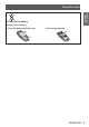
Important Information Read this first! To remove the battery Remote Control Battery 1. Press the guide and lift the cover. 2. Remove the batteries.
Read this first! Important Information Trademarks • Microsoft®, Windows®, Windows Vista®, and Internet Explorer® are the registered trademarks or trademarks of Microsoft Corporation in the United States and/or other countries. • Mac, Mac OS, OS X, and Safari are the trademarks of Apple Inc. registered in the United States and other countries. • PJLinkTM is a trademark or pending trademark in Japan, the United States, and other countries and regions.
Features of the Projector Small size & ultra-high luminance ▶An ▶ ultra high luminance of 20 000 lm*1 is achieved while having a small size due to the unique optical system, cooling, and mechanism design. *1: For PT-DZ21KE and PT-DS20KE. PT-DW17KE has a luminance of 17 000 lm. Easy setup and improved serviceability lineup of optional lenses ▶Extensive ▶ allow more flexible setup of the projector. Improved cost performance in maintenance fee new filter reduces the ▶The ▶ maintenance cost.
Contents Contents Be sure to read “Read this first!”. ( pages 2 to 10) Important Information Important Information Read this first!............................................. 2 Precautions for use....................................15 Preparation Cautions when transporting.............................. 15 Cautions when installing................................... 15 Security............................................................ 18 Disposal......................................................
[COLOR MATCHING].......................................88 [LARGE SCREEN CORRECTION]...................89 [SCREEN SETTING] (PT‑DZ21KE and PT‑DS20KE only)......................................90 [AUTO SIGNAL]...............................................90 [AUTO SETUP]................................................ 91 [RGB IN] (supported during RGB signal input only)..................................................92 [DVI-D IN].........................................................92 [HDMI IN]...........
Contents Important Information Appendix Technical information...............................156 Preparation PJLink protocol............................................... 156 Control commands via LAN............................ 157 / terminal........... 160 terminal............................... 164 Two window display combination list............... 165 Control device password................................ 166 Upgrade kit (only supports PT‑DZ21KE and PT‑DS20KE)....
Precautions for use Cautions when transporting zzThe projection lens (optional accessory) is susceptible to effects due to vibration or impact. Make sure to remove the lens when transporting. zzWhen transporting the projector, hold it securely by its bottom and avoid excessive vibration and impacts. Not doing so may damage the internal parts and result in malfunctions. zzDo not transport the projector with the adjustable feet extended. Doing so may damage the adjustable feet.
Precautions for use Important Information ■■Do not use the projector tilted to the right or left Using the projector at a vertical angle that exceeds 15° may reduce product life or result in malfunction. ■■When installing and using the projector at an angle that exceeds 30° vertically, set [COOLING CONDITION] ( page 100). Failure to observe this will result in malfunctions or shorten the life of the lamp or other components.
zzMake a clearance of at least 5 mm (0.2") between the projector bottom and setting surface by inserting spacers (metallic) etc. between them. Important Information Precautions for use 0RXQW 6SDFHU *DS PP RU PRUH 3OHDVH HQVXUH WKH LQIORZ RI DLU LQWR WKH DLU LQWDNH SRUW 7KLV FRXOG EH D UHDVRQ IRU WKH SURMHFWRU WR QRW ZRUN SURSHUO\ zzThe adjustable feet can be removed if not needed in the installation.
Precautions for use PP RU PRUH PP RU PRUH PP RU PRUH Important Information PP RU PRUH zzDo not install the projector in a confined space. When it is necessary to install the projector in a confined space, install the air conditioning or ventilation separately. Exhaust heat may accumulate when the ventilation is not enough, triggering the protection circuit of the projector. Security When using this product, take safety measures against the following incidents.
zzThe luminance of the lamp will decrease by duration of usage. zzThe lamp may burst with a loud sound or have its service life shortened because of shock, chipping, or degradation due to cumulative operating time. zzThe lamp life varies greatly depending on individual differences and usage conditions. In particular, frequent on/off switching of the power greatly deteriorate the lamp and affect the lamp life. zzContinuous use for over 1 week will deteriorate the lamp.
Precautions for use Important Information Attention zzAfter unpacking the projector, discard the power cord cap and packaging material properly. zzFor missing accessories, consult your dealer. zzStore small parts in an appropriate manner, and keep them away from small children. Note zzThe model numbers of accessories and optional components are subject to change without notice. ■■Contents of the supplied CD-ROM The contents of the supplied CD-ROM are as follows.
Start-up display Start-up display The initial setting screen is displayed when the projector is switched on for the first time after purchase as well as when [ALL USER DATA] ( page 114) in [INITIALIZE] is executed. Set them in accordance with circumstances. In other occasions, you can change the settings by menu operations. ■■Initial setting (display language) ■■Initial setting (projector setup) Select the language to show on the screen. ( page 81) Set each item.
About your projector About your projector Remote control ■■Front Preparation (1) Remote control indicator Flashes if any button in the remote control is pressed. (2) Power standby < > button Sets the projector to the standby mode when the switch on the projector is set to . (3) Power on < > button Starts projection when the switch on the projector is set to when the power is switched off (standby mode).
About your projector ■■Side ■■Top ■■Bottom Remote control wired terminal ( page 27) (19) button Used to prevent unintended operation by careless pressing of the buttons and prevent draining the remote control batteries. Attention zzDo not drop the remote control. zzAvoid contact with liquids or moisture. zzDo not attempt to modify or disassemble the remote control. Note zzThe remote control can be used within a distance of about 30 m (98'5") if pointed directly at the remote control receiver.
About your projector Projector body ■■Front (1) Power indicator The power indicator displays power status. (2) Lamp indicator Displays the status of lamp 1. (3) Lamp indicator Displays the status of lamp 2. (4) Lamp indicator Displays the status of lamp 3. Preparation (5) Lamp indicator Displays the status of lamp 4. (6) Temperature indicator Displays the internal temperature status.
About your projector ■■Bottom Attention zzKeep your hands and other objects away from the air exhaust port. – Keep your hands and face away. – Do not insert your fingers. – Keep heat-sensitive objects away. Heated air from the air outlet port can cause bums, injury, or deformations. zzDo not block the ventilation ports (intake and exhaust) of the projector.
About your projector ■■Connecting terminals PT-DZ21KE, PT-DS20KE zFor z (1) Preparation (5) (2) (3) (6) (4) (7) (8) (9) (10) (11) (12) (8) (9) (10) (12) PT-DW17KE zFor z (1) (2) (6) (3) (4) (7) (1) terminal / terminal These are the terminals to connect the remote control for serial control when the system uses multiple projectors. (2) terminal This is a terminal to remotely control the projector using the external control circuit.
Using the remote control 1) Open the cover. (ii) (i) 2) Insert the batteries and close the cover (insert the side first). zzWhen removing the batteries, perform the steps in reverse order. zzThe ID number set on the remote control will be stored unless it is set again. However, it will be erased if the remote control is left with dead batteries. Set the same ID number again when the batteries are replaced.
Setting Setting up up Projection method You can use the projector with any of the following four projection methods. Select the appropriate method depending on the environment.
Setting up Screen size and throw distance Refer to the following figures and table describing projection distances to install the projector. Image size and image position can be adjusted in accordance with the screen size and screen position.
Setting up ■■[GEOMETRY] projection range (PT-DZ21KE and PT-DS20KE only) [VERTICAL KEYSTONE] (viewed from the side) [HORIZONTAL KEYSTONE] (viewed from above) 6FUHHQ 6FUHHQ Vertical arc correction (viewed from the side) Horizontal arc correction (viewed from above) Getting Started 3URMHFWLRQ GLVWDQFH $UF UDGLXV 3URMHFWLRQ GLVWDQFH $UF UDGLXV 6FUHHQ 6FUHHQ $UF FHQWHU $UF FHQWHU 6FUHHQ 6FUHHQ 3URMHFWLRQ GLVWDQFH $UF UDGLXV 30 - ENGLISH 3URMHFWLRQ GLVWDQFH $UF UDGLXV
Setting up zStandard z Vertical Projection lens trapezoidal Model No. distortion correction angle α (°) ET-D75LE1 ±40 [KEYSTONE] and [CURVED] used together Horizontal trapezoidal distortion correction angle β (°) Vertical trapezoidal distortion correction angle α (°) ±15 ±20 Only for [CURVED] Horizontal trapezoidal Minimum Minimum Minimum Minimum distortion value of R2/ value of R3/ value of R2/ value of R3/ correction L2 L3 L2 L3 angle β (°) ±15 1.0 2.3 0.6 1.
Setting up ■■Projection distance of each projection lens (for PT-DZ21KE) the screen aspect is 16:10 (unit: m) zWhen z Lens type Zoom lens Projection lens Model No. ET-D75LE1 ET-D75LE2 ET-D75LE3 ET-D75LE4 ET-D75LE8 ET-D75LE6 Throw ratio* 1.4 to 1.8:1 1.8 to 2.8:1 2.8 to 4.6:1 4.6 to 7.4:1 7.3 to 13.8:1 0.9 to 1.1:1 1 Screen size Screen Height diagonal*2 (SH) (SD) Projection distance (L) Width (SW) Min. (LW) Max. (LT) Min. (LW) Max. (LT) Min. (LW) Max. (LT) Min. (LW) Max. (LT) Min.
Setting up the screen aspect is 16:9 (unit: m) zWhen z Lens type Zoom lens Projection lens Model No. ET-D75LE1 ET-D75LE2 ET-D75LE3 ET-D75LE4 ET-D75LE8 ET-D75LE6 Throw ratio* 1.4 to 1.8:1 1.8 to 2.8:1 2.8 to 4.6:1 4.6 to 7.4:1 7.3 to 13.8:1 0.9 to 1.1:1 1 Screen Height diagonal*2 (SH) (SD) Projection distance (L) Width (SW) Min. (LW) Max. (LT) Min. (LW) Max. (LT) Min. (LW) Max. (LT) Min. (LW) Max. (LT) Min. (LW) Max. (LT) Min. (LW) Max. (LT) 1.78 (70") 0.872 1.550 2.07 2.
Setting up the screen aspect is 4:3 (unit: m) zWhen z Lens type Zoom lens Projection lens Model No. ET-D75LE1 ET-D75LE2 ET-D75LE3 ET-D75LE4 ET-D75LE8 ET-D75LE6 Throw ratio* 1.6 to 2.2:1 2.2 to 3.3:1 3.3 to 5.5:1 5.6 to 8.9:1 8.8 to 16.5:1 1.1 to 1.3:1 1 Screen size Screen Height diagonal*2 (SH) (SD) Projection distance (L) Width (SW) Min. (LW) Max. (LT) Min. (LW) Max. (LT) Min. (LW) Max. (LT) Min. (LW) Max. (LT) Min. (LW) Max. (LT) Min. (LW) Max. (LT) Getting Started 1.
Setting up ■■Projection distance of each projection lens (for PT-DS20KE) the screen aspect is 4:3 (unit: m) zWhen z Lens type Zoom lens Projection lens Model No. ET-D75LE1 ET-D75LE2 ET-D75LE3 ET-D75LE4 ET-D75LE8 ET-D75LE6 Throw ratio* 1.5 to 2.0:1 2.0 to 3.0:1 3.0 to 5.0:1 5.0 to 8.0:1 7.9 to 15.0:1 1.0 to 1.2:1 1 Projection distance (L) Width (SW) Min. (LW) Max. (LT) Min. (LW) Max. (LT) Min. (LW) Max. (LT) Min. (LW) Max. (LT) Min. (LW) Max. (LT) Min. (LW) Max. (LT) 1.
Setting up the screen aspect is 16:9 (unit: m) zWhen z Lens type Zoom lens Projection lens Model No. ET-D75LE1 ET-D75LE2 ET-D75LE3 ET-D75LE4 ET-D75LE8 ET-D75LE6 Throw ratio* 1.5 to 2.0:1 2.0 to 3.0:1 3.0 to 5.0:1 5.0 to 8.0:1 8.0 to 15.0:1 1.0 to 1.2:1 1 Screen size Screen Height diagonal*2 (SH) (SD) Projection distance (L) Width (SW) Min. (LW) Max. (LT) Min. (LW) Max. (LT) Min. (LW) Max. (LT) Min. (LW) Max. (LT) Min. (LW) Max. (LT) Min. (LW) Max. (LT) 1.78 (70") 0.872 1.
Setting up ■■Projection distance of each projection lens (for PT-DW17KE) the screen aspect is 16:9 (unit: m) zWhen z Lens type Zoom lens Projection lens Model No. ET-D75LE1 ET-D75LE2 ET-D75LE3 ET-D75LE4 ET-D75LE8 ET-D75LE6 Throw ratio* 1.5 to 2.0:1 2.1 to 3.1:1 3.1 to 5.2:1 5.2 to 8.2:1 8.2 to 15.4:1 1.0 to 1.2:1 1 Projection distance (L) Width (SW) Min. (LW) Max. (LT) Min. (LW) Max. (LT) Min. (LW) Max. (LT) Min. (LW) Max. (LT) Min. (LW) Max. (LT) Min. (LW) Max. (LT) 7.94 7.
Setting up the screen aspect is 4:3 (unit: m) zWhen z Lens type Zoom lens Projection lens Model No. ET-D75LE1 ET-D75LE2 ET-D75LE3 ET-D75LE4 ET-D75LE8 ET-D75LE6 Throw ratio* 2.0 to 2.7:1 2.7 to 4.1:1 4.1 to 6.9:1 6.9 to 11.0:1 10.9 to 20.5:1 1.4 to 1.6:1 1 Screen size Screen Height diagonal*2 (SH) (SD) Projection distance (L) Width (SW) Min. (LW) Max. (LT) Min. (LW) Max. (LT) Min. (LW) Max. (LT) Min. (LW) Max. (LT) Min. (LW) Max. (LT) Min. (LW) Max. (LT) Getting Started 1.
Setting up To use a screen size not listed in this manual, check the screen size SD and use the following formula to calculate projection distance. The unit of the calculation result is m. ■■Formula to calculate projection distance per projection lens (for PT-DZ21KE) ET-D75LE1 ET-D75LE2 ET-D75LE3 ET-D75LE4 Zoom lens ET-D75LE8 ET-D75LE6 ET-D75LE10 ET-D75LE20 ET-D75LE30 Throw ratio Aspect ratio 1.4 to 1.8:1 16:10 1.4 to 1.8:1 16:9 1.6 to 2.2:1 4:3 1.8 to 2.8:1 16:10 1.8 to 2.
Setting up Projection lens Zoom lens ET-D75LE40 ET-D75LE5 Fixed-focus lens ET-D75LE50 Throw ratio Aspect ratio 4.6 to 7.4:1 16:10 4.6 to 7.4:1 16:9 5.5 to 8.9:1 4:3 0.7:1 0.7:1 0.8:1 0.7:1 0.7:1 0.8:1 16:10 16:9 4:3 16:10 16:9 4:3 Projection distance (L) formula Min. (LW) Max. (LT) Min. (LW) Max. (LT) Min. (LW) Max. (LT) — — — — — — L = 3.9528 x SD (m) – 0.1577 L = 6.3031 x SD (m) – 0.1615 L = 4.0630 x SD (m) – 0.1577 L = 6.4764 x SD (m) – 0.1615 L = 4.4764 x SD (m) – 0.1577 L = 7.
Setting up ■■Formula to calculate projection distance per projection lens (for PT-DW17KE) Throw ratio Aspect ratio 1.5 to 2.0:1 16:9 2.0 to 2.7:1 4:3 2.1 to 3.1:1 16:9 2.7 to 4.1:1 4:3 3.1 to 5.2:1 16:9 4.1 to 6.9:1 4:3 5.2 to 8.2:1 16:9 6.9 to 11.0:1 4:3 8.2 to 15.4:1 16:9 10.9 to 20.5:1 4:3 1.0 to 1.2:1 16:9 1.4 to 1.6:1 4:3 1.4 to 1.9:1 16:9 1.9 to 2.5:1 4:3 1.8 to 2.7:1 16:9 2.5 to 3.6:1 4:3 2.7 to 5.2:1 16:9 3.6 to 6.9:1 4:3 5.1 to 8.2:1 16:9 6.8 to 10.
Setting up Adjusting adjustable feet Install the projector on a flat surface so that the front of the projector is parallel to the screen surface and the projection screen is rectangular. If the screen is tilted downward, the projection screen can be adjusted to be rectangular by adjusting the adjustable feet. The adjustable feet can also be used to adjust the projector to be level when it is tilted in a horizontal direction.
Attaching/removing thethe projection lens Attaching/removing projection lens(optional (optionalaccessory) accessory) Move the lens to the home position before replacing or removing the lens. ( page 53) Attention zzReplace the projection lens after turning off the power of the projector. zzDo not touch the lens signal receiver. Dust or dirt may cause defective contact. zzDo not touch the lens surface with your bare hands.
Connecting Connecting Before connecting zzBefore connecting, carefully read the operating instructions for the external device to be connected. zzTurn off the power of all devices before connecting cables. zzAcquire any connection cable necessary to connect the external device to the system that is either not supplied with the device or not available as an option. zzVideo signals containing too much jitter may cause the images on the screen to randomly wobble or wafture.
Connecting ■■ terminal pin assignments and signal names (24) (17) (16) (9) (8) (1) Pin No. Signal name Pin No. Signal name (1) (2) (3) (4) (5) (6) (7) (8) (9) (10) (11) (12) T.M.D.S data 2– T.M.D.S data 2+ T.M.D.S data 2/4 shield — — DDC clock DDC data — T.M.D.S data 1– T.M.D.S data 1+ T.M.D.S data 1/3 shield — (13) (14) (15) (16) (17) (18) (19) (20) (21) (22) (23) (24) — +5 V GND Hot plug detection T.M.D.S data 0– T.M.D.S data 0+ T.M.D.S data 0/5 shield — — T.M.D.S clock shield T.M.
Connecting ■■For / terminals (for PT-DZ21KE and PT-DS20KE only) +' 6', VLJQDO RU 6' 6', VLJQDO 'LJLWDO 9&5 IRU FRPPHUFLDO XVH Getting Started Note zzUse [SYSTEM SELECTOR] ( page 70) to switch the input format. zzSome external devices to be connected require [SDI IN] ( page 93) to be set. zzUse a 5CFB or higher (such as 5CFB, or 7CFB) or a Belden 1694A or higher connection cable to properly transmit images. Use a connection cable of 100 m (328'1") length or less.
Connecting Connecting example: Computers The following diagram is a connecting example for PT-DZ21KE and PT-DS20KE. &RPSXWHU IRU FRQWURO Getting Started &RPSXWHU &RPSXWHU &RPSXWHU &RPSXWHU Note zzThe terminal supports single links only. zzFor signals that the projector can project, refer to “List of compatible signals” ( page 167). zzIf you operate the projector using the computer with the resume feature (last memory), you may have to reset the resume feature to operate the projector.
Switching the projector Switching on/offon/off the projector Connecting the power cord Make sure that the supplied power cord is fully inserted into the projector to prevent removal of the power cord. Confirm that the switch is on the side before connecting the power cord. For detailed power cord handling, refer to “Read this first!” ( pages 2 to 10).
Switching on/off the projector Power indicator The power indicator displays the status of the power. Check the status of the power indicator before operating the projector. Power indicator Status Red Lit Green Lit Orange Lit The main power is switched off. The power is switched off. (Standby mode.) Projection will start if the power on < > button is pressed.
Switching on/off the projector 3) 5) 4) 8) 10) 11) 12) 3) 5) 4) 11) 6) 9) 7) Switching on the projector Install the projection lens before switching on the projector. ( page 43) Remove the lens cover first. 1) 9) 6) 8) 10) 12) 2) Making adjustments and selections 1) Connect the power plug to an outlet. It is recommended that images are projected continuously for at least 30 minutes before the focus is adjusted. 2) Press the side of the switch to turn on the power.
Switching on/off the projector 3) 1) 2) 4) 1) 2) Switching off the projector 1) Press the power standby < > button. 2) Press ◀▶ to select [OK], and press the button. (Or press the power standby < > button again) zzProjection of the image will stop, and the power indicator on the projector lights in orange. (The fan keeps running.
Projecting Projecting Check the projection lens attachment ( page 43), external device connection ( page 44), power cord connection ( page 48), switch on the power ( page 50) to start projecting. Select the video for projection, and adjust appearance of the projected image. Select the input signal Select an input signal. 1) Switch on the external devices. zzPress the play button on an external device, such as a Blu-ray disc player.
Projecting Moving the lens to the home position 1) Press the button on the control panel or the button on the remote control for at least three seconds. 2) While the [HOME POSITION] menu is displayed (for approximately five seconds), press the button. LENS HOME POSITION ENTER EXECUTE MENU CANCEL zz[PROGRESS] is displayed in the menu screen, and the lens returns to the home position.
Projecting Adjustment range by the lens position shift (optical shift) Perform the lens position shift within the adjustment range. The focus may change when the lens position is shifted out of the adjustment range. This is because the movement of the lens is restricted to protect the optical parts. Projection position can be adjusted with the optical axis shift based on the standard projection position in the range shown in the following figures.
Projecting Adjusting the lens mounter when the focus is unbalanced ■■Focus balance between the tilt of the lens and the screen focus surface zRelationship z When the projection lens is tilted in contrast with the image forming surface, tilting the front side (screen side) of the projection lens downwards (in the direction of the dotted arrow line), the upper side of the screen focus surface will tilt inwards and the lower side will tilt outwards.
Projecting When a projection lens with a large weight is installed, or when the projector is installed in an inclination, the lens may tilt and the focus may become unbalanced. In these cases, refer to Figure 3 and the adjustment examples in the table below, and perform adjustments through the following procedures. procedure zAdjustment z 1) Press the button or the button on the remote control on the control panel to display the focus adjustment menu.
Projecting When the just focus point of When the just focus point of When the just focus point of When the just focus point the screen in V up is in the the screen in V bottom is in the screen in H left is in the of the screen in H right is in inner side of the screen the inner side of the screen inner side of the screen the inner side of the screen — — (b) — Rotate counter clockwise Rotate counter clockwise (c) — Rotate counter clockwise — — — Rotate counter clockwise Basic Operation (a) Rotate
Remote control operation Remote control operation Using the on-screen display function Turn off the on-screen display function (no display) when you do not wish the viewers to see the onscreen display, such as the menu or the input terminal name. button 1) Press the button on the remote control. zzThe on-screen display disappears. 2) Press the button again. zzThe on-screen display appears.
Using the STATUS function You can display the status of the projector. button Press the button on the remote control. zzThe [STATUS] screen is displayed. STATUS 1/4 INPUT RGB2 SIGNAL NAME XGA60-A8 SIGNAL FREQUENCY 48.36kHz/ 60.03Hz PROJECTOR RUNTIME 140h LAMP1 68h/ ON/ LAMP2 69h/ ON/ LAMP3 0h/ OFF/ LAMP4 0h/ OFF/ INTAKE AIR TEMP. 27°C/ 80°F OPTICS MODULE TEMP. 33°C/ 92°F AROUND LAMP TEMP.
Remote control operation Displaying the internal test pattern The projector has eight types of internal test patterns to check the condition of the set. To display test patterns, perform the following steps. button 1) Press the button on the remote control. 2) Press the ◀▶ button to select the test pattern. Note zzSetting is also available from the [TEST PATTERN] menu ( page 117). zzSettings of position, size, and other factors will not be reflected in test patterns.
Menu navigation Menu navigation The on-screen menu (Menu) is used to perform various settings and adjustments of the projector. Navigating through the menu ■■Operating procedure button 4) Press ▲▼ to select a sub-menu, and the ◀▶ buttons or the button to change or adjust settings. zzFor some items, press the ◀▶ button to display an individual adjustment screen with a bar scale as shown in the following diagram. &/2&.
Menu navigation ■■To reset adjustment values to the factory default If the button on the remote control is pressed, the values adjusted in the menu items will be restored to the factory default settings. button Press the button on the remote control. &/2&. 3+$6( $'-867 Note zzYou cannot reset all the settings to the factory default at a time.
Menu navigation ■■[ADVANCED MENU] The sub-menu of the selected main menu item is displayed, and you can set and adjust items in the sub-menu. ■■[PICTURE] Factory Page default [STANDARD]*1 65 [PICTURE MODE] [CONTRAST] [0] 66 [BRIGHTNESS] [0] 66 66 [COLOR] [2]*1 [TINT] [–2] 66 [COLOR TEMPERATURE] [DEFAULT] 66 [GAMMA] [DEFAULT] 68 [SYSTEM DAYLIGHT VIEW] [OFF] 68 [SHARPNESS] [8] 68 [NOISE REDUCTION] [2] 69 [DYNAMIC IRIS] [2] 69 70 [SYSTEM SELECTOR] [YPBPR]*1 Sub-menu item *1: Depends on the signal input.
Menu navigation ■■[P IN P] ■■[DISPLAY OPTION] Factory default [OFF] Sub-menu item [COLOR MATCHING] [LARGE SCREEN CORRECTION] [SCREEN SETTING]*1 [AUTO SIGNAL] [AUTO SETUP] [RGB IN] [DVI-D IN] [HDMI IN] [SDI IN]*1 [ON-SCREEN DISPLAY] [BACK COLOR] [STARTUP LOGO] [UNIFORMITY] [SHUTTER SETTING] [FREEZE] [WAVEFORM MONITOR] [CUT OFF] Page 88 [OFF] 89 — [OFF] — — — — — — [BLUE] [DEFAULT LOGO] — — — [OFF] — 90 90 91 92 92 93 93 94 95 95 95 96 96 96 98 *1: PT-DZ21KE and PT-DS20KE only [PROJECTOR ID] [PROJECT
Select [PICTURE] from the main menu, and select the item from the sub-menu. Refer to “Navigating through the menu” ( page 61) for the operation of the menu screen. zzAfter selecting the item, press ▲▼◀▶ to set. [PICTURE MODE] You can switch to the desired picture mode suitable for the image source and the environment in which the projector is used. 1) Press ▲▼ to select [PICTURE MODE]. 2) Press ◀▶ . zzThe [PICTURE MODE] individual adjustment screen is displayed.
[PICTURE] menu [CONTRAST] [TINT] You can adjust the contrast of the colors. You can adjust the skin tone in the projected image. 1) Press ▲▼ to select [CONTRAST]. 1) Press ▲▼ to select [TINT]. 2) Press ◀▶ or the button. 2) Press ◀▶ or the button. 3) Press ◀▶ to adjust the level. 3) Press ◀▶ to adjust the level. zzThe [CONTRAST] individual adjustment screen is displayed. Operation Adjustment Range Press ▶ .
[PICTURE] menu 4) Select [USER1] or [USER2] in Step 3). 8) Press ◀▶ to select [OK], and press the button. zzThe [USER1] or [USER2] data is overwritten. zzIf you press ◀▶ to select [CANCEL] and then press the button, the data will not be overwritten. zzThe [WHITE BALANCE HIGH] screen is displayed. 5) Press the button. zzThe [COLOR TEMPERATURE] screen is displayed. 6) Press ▲▼ to select [WHITE BALANCE]. 9) 7) Press the button. zzThe [WHITE BALANCE] screen is displayed.
[PICTURE] menu [GAMMA] [SYSTEM DAYLIGHT VIEW] Switch gamma mode. 1) Press ▲▼ to select [GAMMA]. 2) Press ◀▶ or the button. zzThe [GAMMA] individual adjustment screen is displayed. 3) Press ◀▶ to switch the [GAMMA]. zzThe setting will change as follows each time you press the button. [DEFAULT]*1 [USER1] [2.8] [USER2] (0.1 increments) [DICOM SIM.] [1.0] [2.0] [1.8] *1: When [PICTURE MODE] is set to [DYNAMIC], [USER], or [DICOM SIM.], [DEFAULT] cannot be selected.
[PICTURE] menu [NOISE REDUCTION] You can reduce noises when the input image is degraded and noise is occurring in the image signal. 1) Press ▲▼ to select [NOISE REDUCTION]. zzThe [NOISE REDUCTION] individual adjustment screen is displayed. 3) Press ◀▶ to switch the [NOISE REDUCTION]. zzThe setting will change as follows each time you press the button. [2] (Medium) 6) Press ▲▼ to select the item you want to adjust, and press ◀▶ to adjust the correction amount.
[PICTURE] menu [SYSTEM SELECTOR] The projector will automatically detect the input signal, but you can set the system method manually when an unstable signal is input. Set the system method matching the input signal. 1) Press ▲▼ to select [SYSTEM SELECTOR]. 2) Press the button. 3) Press ▲▼ to select a system format. 4) Press the button. ■■When using
[PICTURE] menu link zSingle z During SDI1 input, select [AUTO], [480i YCBCR], [576i YCBCR], [720/50p YPBPR], [720/60p YPBPR], [1035/60i YPBPR], [1080/24p YPBPR], [1080/24sF YPBPR], [1080/25p YPBPR], [1080/30p YPBPR], [1080/50i YPBPR], [1080/60i YPBPR], [1080/50p YPBPR], [1080/60p YPBPR], [1080/24p RGB], [1080/24sF RGB], [1080/25p RGB], [1080/30p RGB], [1080/50i RGB], or [1080/60i RGB].
[POSITION] [POSITION] menu menu Select [POSITION] from the main menu, and select the item from the sub-menu. Refer to “Navigating through the menu” ( page 61) for the operation of the menu screen. zzAfter selecting the item, press ▲▼◀▶ to set. [ASPECT] You can switch the aspect ratio of the image. The aspect ratio is switched within the screen range selected in [SCREEN SETTING]. Set [SCREEN SETTING] first.( page 90) 1) Press ▲▼ to select [ASPECT]. 2) Press ◀▶ or the button.
[POSITION] menu When standard signals*1 are input, the pictures are displayed with the aspect ratio converted to 16:9. When wide-screen signals*2 are input, the pictures are displayed without changing the aspect ratio. ■■[4:3] When standard signals*1 are input, the pictures are displayed without changing the aspect ratio. When wide-screen signals*2 are input and [4:3] is selected in [SCREEN FORMAT], the pictures are displayed with the aspect ratio changed to 4:3.
[POSITION] menu [CLOCK PHASE] You can adjust to achieve an optimal image when there is a flickering image or smeared outlines. 1) Press ▲▼ to select [CLOCK PHASE]. 2) Press ◀▶ or the button. zzThe [CLOCK PHASE] individual adjustment screen is displayed. 3) Press ◀▶ to adjust the level. zzAdjustment value will change between [0] and [31]. Adjust so that the amount of interference is at a minimum. Note zzCertain signals may not be adjustable.
[POSITION] menu KEYSTONE] z[HORIZONTAL z BALANCE] z[VERTICAL z Adjust the setting according to the lens shift range in vertical direction. ARC] z[HORIZONTAL z BALANCE] z[VERTICAL z BALANCE] z[HORIZONTAL z BALANCE] z[HORIZONTAL z Adjust the setting according to the lens shift range in horizontal direction. ■■[CURVED] THROW RATIO] z[LENS z Set the throw ratio for the lens used. Settings KEYSTONE] z[VERTICAL z Note zzThe menu or logo may extend beyond the edge of the screen when [GEOMETRY] is set.
[POSITION] menu [KEYSTONE] (PT-DW17KE only) You can correct the trapezoidal distortion that occurs when the projector is installed tilted or when the screen is tilted. 1) Press ▲▼ to select [KEYSTONE]. 2) Press the button. 3) Press ▲▼ to select the item to adjust. 4) Press ◀▶ to adjust the level. ■■[KEYSTONE] ■■[SUB KEYSTONE] ■■[LINEARITY] Settings Note zzThe menu or logo may run off the screen when various adjustments are performed with [KEYSTONE].
[ADVANCED MENU] Select [ADVANCED MENU] from the main menu, and select the item from the sub-menu. Refer to “Navigating through the menu” ( page 61) for the operation of the menu screen. zzAfter selecting the item, press ▲▼◀▶ to set. [ADVANCED MENU] [BLANKING] The blanking width is adjusted when there are noise at the edge of the screen or the image is slightly running out from the screen when an image from the VCR or other devices are projected. 1) Press ▲▼ to select [BLANKING].
[ADVANCED MENU] [INPUT RESOLUTION] You can adjust to achieve an optimal image when there is a flickering image or smeared outlines. 1) Press ▲▼ to select [INPUT RESOLUTION]. 2) Press the button. zzThe [INPUT RESOLUTION] screen is displayed. 3) Press ▲▼ to select [TOTAL DOTS], [DISPLAY DOTS], [TOTAL LINES], or [DISPLAY LINES], and press ◀▶ to adjust it. zzValues corresponding to the input signal are displayed automatically for each item.
[ADVANCED MENU] ■■To display the adjustment marker 7) Press ▲▼ to select [MARKER]. 8) Press ◀▶ to switch [ON]. zzA marker for image position adjustment is displayed. The position where the red and green lines overlap for the sets to join will be the optimal point. Make sure to set the correction width for the sets to join as the same value. Optimal joining is not possible with the sets with different correction widths. The optimal point is the point where this line overlaps. 17) Press the button.
[ADVANCED MENU] [FRAME RESPONSE] [RASTER POSITION] Image processing is simplified when 1080/60i, 1080/50i, and 1080/24sF signals are input to reduce image frame delay. This will allow the position of the image to move within the display area arbitrarily when the input image is not using the whole display area. 1) Press ▲▼ to select [FRAME RESPONSE]. 1) Press ▲▼ to select [RASTER POSITION]. 2) Press ◀▶ to switch [FRAME RESPONSE]. 2) Press the button.
[DISPLAY LANGUAGE] menu [DISPLAY LANGUAGE] menu Select [DISPLAY LANGUAGE] from the main menu, and display the sub-menu. Refer to “Navigating through the menu” ( page 61) for the operation of the menu screen. zzPress ▲▼ to select a language, and press the button to set. Changing the display language You can select the language of the on-screen display. DISPLAY LANGUAGE SELECT SET Settings ENTER zzVarious menus, settings, adjustment screens, control button names, etc.
[3D SETTINGS] [3D SETTINGS] menumenu (PT‑DZ21KE and PT‑DS20KE only) only) (PT‑DZ21KE and PT‑DS20KE Select [3D SETTINGS] from the main menu, and select the item from the sub-menu. Refer to “Navigating through the menu” ( page 61) for the operation of the menu screen. zzAfter selecting the item, press ▲▼◀▶ to set. [3D SYNC SETTING] Set the way in which the <3D SYNC 1 IN/OUT> terminal and the <3D SYNC 2 OUT> terminal will be used.
[3D SETTINGS] menu (PT‑DZ21KE and PT‑DS20KE only) set in [3D SYNC2] zItems z [OFF] Not used.
[3D SETTINGS] menu (PT‑DZ21KE and PT‑DS20KE only) [3D INPUT FORMAT] Set the 3D format for the image signals being input. Set a 3D format that matches the input signal. 1) Press ▲▼ to select [3D INPUT FORMAT]. 2) Press the button. zzThe [3D INPUT FORMAT] screen is displayed. 3) Press ▲▼ to select a 3D format. 4) Press the button. [AUTO]*1 Automatically detects 3D format of input image signals and displays images. [NATIVE] Forcibly displays images in 2D regardless of input image signals.
[3D SETTINGS] menu (PT‑DZ21KE and PT‑DS20KE only) Correct a shift when the brightness or color differ in the right eye and left eye images. 1) Press ▲▼ to select [3D PICTURE BALANCE]. 2) Press the button. zzThe [3D PICTURE BALANCE] screen is displayed. 3) Press ▲▼ to select an item, and press ◀▶ to adjust the setting. zzCorrect the setting value parts of the right eye image based on the left eye image. [CONTRAST] You can adjust the contrast of the colors.
[3D SETTINGS] menu (PT‑DZ21KE and PT‑DS20KE only) [3D FRAME DELAY] [3D TEST PATTERN] Adjust the timing of the left-right switch of an image. 1) Press ▲▼ to select [3D FRAME DELAY]. 2) Press ◀▶ to switch [3D FRAME DELAY]. zzValues in the following range change by units of 10 us. 0 us to 25 000 us [3D TEST MODE] Set the image display format for use with 3D system adjustments. 1) Press ▲▼ to select [3D TEST MODE].
[3D SETTINGS] menu (PT‑DZ21KE and PT‑DS20KE only) Set to show or hide safety precaution messages related to 3D viewing when the projector is switched on. 1) Press ▲▼ to select [SAFETY PRECAUTIONS MESSAGE]. 2) Press ◀▶ to switch [SAFETY PRECAUTIONS MESSAGE]. zzThe setting will change as follows each time you press the button. [ON] [OFF] [ON] Shows safety precaution messages related to 3D viewing when the projector is switched on.
[DISPLAY OPTION] menu [DISPLAY OPTION] menu Select [DISPLAY OPTION] from the main menu, and select the item from the sub-menu. Refer to “Navigating through the menu” ( page 61) for the operation of the menu screen. zzAfter selecting the item, press ◀▶ to set. ■■To set [3COLORS] or [7COLORS] 3) Select [3COLORS] or [7COLORS] in Step 2). 4) Press the button. zzThe [3COLORS] or [7COLORS] screen is displayed.
[DISPLAY OPTION] menu ■■To use a colorimeter to adjust the color matching Use a colorimeter that can measure chromaticity coordinates and luminance to change the colors [RED], [GREEN], [BLUE], [CYAN], [MAGENTA], [YELLOW], and [WHITE] to desired colors. the current luminance and zInputting z chromaticity coordinates 1) Press ▲▼ to select [COLOR MATCHING]. 2) Press ◀▶ to select [709MODE] or [MEASURED]. 3) Press the button. zzThe [709MODE] or [MEASURED MODE] screen is displayed.
[DISPLAY OPTION] menu [SCREEN SETTING] (PT‑DZ21KE and PT‑DS20KE only) Set the screen size. When changing the aspect of a projected image, correct to the optimum image position for the set screen. Set as necessary for the screen in use. ■■For PT-DZ21KE 2) Press ◀▶ to switch [AUTO SIGNAL]. zzThe setting will change as follows each time you press the button. 2) Press the button. zzThe [SCREEN SETTING] screen is displayed. 3) Press ◀▶ to switch [SCREEN FORMAT].
[DISPLAY OPTION] menu ■■To adjust position automatically You can set when adjusting a special signal or horizontally long (16:9, etc.) signal. 1) Press ▲▼ to select [AUTO SETUP]. 2) Press the button. zzThe [AUTO SETUP] screen is displayed. 3) Press ▲▼ to select an item. ■■To set [MODE] 4) Select [MODE] in Step 3). 5) Press ◀▶ to switch [MODE]. zzThe setting will change as follows each time you press the button. [DEFAULT] [DEFAULT] [WIDE] [USER] Standard setting.
[DISPLAY OPTION] menu [RGB IN] (supported during RGB signal input only) Set to match the signal to input to the terminal. 1) Press ▲▼ to select [RGB IN]. 2) Press the button. 4) Press ◀▶ to switch [DVI EDID]. zzThe setting will change as follows each time you press the button. [EDID3] [EDID3] zzThe [RGB IN] screen is displayed. 3) Press ▲▼ to select an item. ■■To set [RGB1 INPUT SETTING] [EDID1] 4) Select [RGB1 INPUT SETTING] in Step 3).
[DISPLAY OPTION] menu [SDI IN] (PT‑DZ21KE and PT‑DS20KE Switch the setting when the projector is connected to an external device via an HDMI cable and the image is not projected correctly. 1) Press ▲▼ to select [HDMI IN]. 2) Press the button. zzThe [HDMI IN] screen is displayed. 3) Press ◀▶ to switch [HDMI SIGNAL LEVEL]. zzThe setting will change as follows each time you press the button.
[DISPLAY OPTION] menu ■■To set [BIT DEPTH] ■■[OSD POSITION] 4) Select [BIT DEPTH] in Step 3). Set the position of the menu screen (OSD). zzThe setting will change as follows each time you press the button. 5) Press ◀▶ to switch [BIT DEPTH]. zzThe setting will change as follows each time you press the button. [AUTO] [12-bit] Automatically select 12 bits or 10 bits. [12-bit] Fix to 12 bits. [10-bit] Fix to 10 bits. ■■To set [3G-SDI MAPPING] 4) Select [3G-SDI MAPPING] in Step 3).
[DISPLAY OPTION] menu ■■[INPUT GUIDE] 2) Press ◀▶ to switch [STARTUP LOGO]. Set display of the input terminal name, signal name and memory number currently selected in the position set by the [OSD POSITION]. zzThe setting will change as follows each time you press the button. [DEFAULT LOGO] You can set the display/hide of the warning message. zzThe setting will change as follows each time you press the button. [ON] [OFF] [BACK COLOR] Set the color of the projected image when there is no signal input.
[DISPLAY OPTION] menu ■■To set [PC CORRECTION] To use the [PC CORRECTION] function, an optional upgrade kit (Model No.: ET-UK20) is required. To purchase the product, consult your dealer. 5) Press ◀▶ to switch. zzThe setting will change as follows each time you press the button. [OPEN] 4) Select [PC CORRECTION] in Step 3). 5) Press ◀▶ to switch. zzThe setting will change as follows each time you press the button.
[DISPLAY OPTION] menu 2) Press ◀▶ to switch [WAVEFORM MONITOR]. zzThe setting will change as follows each time you press the button. [OFF] [ON] 3) Press the
[DISPLAY OPTION] menu [CUT OFF] Each red, green and blue color component can be removed. 1) Press ▲▼ to select [CUT OFF]. 2) Press the button. zzThe [CUT OFF] screen is displayed. 3) Press ▲▼ to select [RED], [GREEN], or [BLUE]. 4) Press ◀▶ to switch. zzThe setting will change as follows each time you press the button. [OFF] [ON] [OFF] Disables cutoff. [ON] Enables cutoff. Note zzWhen input is switched or a signal is switched, the cutoff setting returns to its original setting (off).
[PROJECTOR SETUP] menu [PROJECTOR SETUP] menu Select [PROJECTOR SETUP] from the main menu, and select the item from the sub-menu. Refer to “Navigating through the menu” ( page 61) for the operation of the menu screen. zzAfter selecting the item, press ▲▼◀▶ to set. [PROJECTION METHOD] Set the projection method in accordance with the installation status of the projector. Change the projection method if the screen display is upside down or inverted. 1) Press ▲▼ to select [PROJECTION METHOD].
[PROJECTOR SETUP] menu [COOLING CONDITION] Change the fan control depending on the direction of projection. Set [COOLING CONDITION] correctly in accordance with the direction of projection referencing the following figure. It may shorten the life of the lamp if used in incorrect setting. 1) Press ▲▼ to select [COOLING CONDITION]. 2) Press the button. zzThe [COOLING CONDITION] screen is displayed. 3) Press ▲▼ to select a cooling condition.
[PROJECTOR SETUP] menu Note zzFor a set time after [LAMP SELECT] is switched, [LAMP SELECT] cannot be switched again, because the speed of the lamp replacement cycle will increase. Repeatedly switching [LAMP SELECT] in a short time will also increase the speed of the lamp replacement cycle. zzThe colors of the items indicate the status.
[PROJECTOR SETUP] menu [BRIGHTNESS CONTROL] The projector is equipped with a luminance sensor to measure brightness and functions to correct screen brightness resulting from changes in lamp brightness. Use the projector when using multiple projectors to display on multiple screens to reduce changes in overall brightness of the multiple screens due to lamp degradation and suppress variation in brightness to preserve uniformity. 1) Press ▲▼ to select [BRIGHTNESS CONTROL]. 2) Press the button.
[PROJECTOR SETUP] menu 11) Press the button. 12) Enter the time and press the button zzMeasure brightness at a specified time. Dynamic iris is fixed to open during measurement. 13) Press ▲▼ to select [CALIBRATION MESSAGE]. 14) Press ◀▶ to switch [CALIBRATION MESSAGE]. zzThe setting will change as follows each time you press the button. [ON] [OFF] [ON] Displays a message during calibration. [OFF] Does not display a message during calibration. 15) Press ▲▼ to select [APPLY].
[PROJECTOR SETUP] menu ■■To set [BRIGHTNESS CONTROL STATUS] Displays the luminance control status. 4) Select [BRIGHTNESS CONTROL STATUS] in Step 3). 5) Press the button. zzThe [BRIGHTNESS CONTROL STATUS] screen is displayed. [MODE] in [BRIGHTNESS zWhen z CONTROL SETUP] is [OFF] Displays the luminance control disabled status. Displays the luminance control status of connected projectors (up to eight), including projectors operated by the on-screen menu. %5,*+71(66 &21752/ 67$786 /,1.
[PROJECTOR SETUP] menu Error message [Exceed maximum number of projectors.] Remedy zzSet no more than eight projectors in one group. zzUse a computer and the dedicated “Multi Projector Monitoring & Control Software”*1 to connect nine or more projectors. zzSet the on-screen menu [NETWORK CONTROL] [COMMAND CONTROL] to [ON] for the projector [Please check the in error. COMMAND CONTROL zzSet the [NETWORK setting.] CONTROL] [COMMAND PORT] of all projectors to be connected to the same value.
[PROJECTOR SETUP] menu 10) Set [BRIGHTNESS CONTROL GAIN] of all projectors to 100%. 11) Set [BRIGHTNESS CONTROL GAIN] of the darkest projector to 90%. 12) Adjust [BRIGHTNESS CONTROL GAIN] to match the [BRIGHTNESS CONTROL GAIN] set to 90% of the other projectors. 13) Set [MODE] in [BRIGHTNESS CONTROL SETUP] of all projectors to [AUTO], and [LINK] to [GROUP A]. 14) Select [APPLY] in [BRIGHTNESS CONTROL SETUP] on all projectors and press the button. zzLuminance control starts.
[PROJECTOR SETUP] menu 10) Press ◀▶ to switch [COMMAND]. zzThe setting will change as follows each time you press the button. [POWER ON] [STANDBY] [SHUTTER]*1 [P IN P]*1 [LAMP SELECT]*1 [INPUT]*1 *1: Displays the details set in Step 12). 11) Press the button. zzThe [COMMAND] detailed setting screen is displayed. 12) Press ▲▼ to select a command. zzFor [SHUTTER], [INPUT], [LAMP SELECT], and [P IN P], the setting will change as follows each time you press the button.
[PROJECTOR SETUP] menu ■■To set the response [RS-232C] Set the communication conditions of the / terminal. 1) Press ▲▼ to select [RS-232C]. 2) Press the button. zzThe [RS-232C] screen is displayed. 4) Select [RESPONSE(ID ALL)] in Step 3). 5) Press ◀▶ to switch [RESPONSE(ID ALL)]. zzThe setting will change as follows each time you press the button. [ON] 3) Press ▲▼ to select an item.
[STATUS] Displays the status of the projector. 1) Press ▲▼ to select [STATUS]. 2) Press the button. zzThe [STATUS] screen is displayed. 3) Press ◀▶ to switch the pages. [INPUT] [SIGNAL NAME] [SIGNAL FREQUENCY] [PROJECTOR RUNTIME] [LAMP1] [LAMP2] [LAMP3] [LAMP4] [INTAKE AIR TEMP.] [OPTICS MODULE TEMP.] [AROUND LAMP TEMP.] [REMOTE2 STATUS] [PROJECTOR TYPE] [SERIAL NUMBER] [LAMP UNIT MODEL NO.
[PROJECTOR SETUP] menu [NO SIGNAL SHUT-OFF] You can set the power of the projector automatically to standby if there is no input signal by the specified time. 1) Press ▲▼ to select [NO SIGNAL SHUT-OFF]. 2) Press ◀▶ to switch [NO SIGNAL SHUT-OFF]. [DISABLE] [10MIN.] [90MIN.] Disables the No signal shut-off function. Allows you to set in ten minutes intervals. You can set the terminal. 1) Press ▲▼ to select [REMOTE2 MODE]. 2) Press ◀▶ to switch [REMOTE2 MODE].
[PROJECTOR SETUP] menu ■■To adjust the date and time manually 4) Select [ADJUST CLOCK] in Step 3). [LENS CALIBRATION] Automatically set the lens shift limit values and home position for the projector. 5) Press the button. 1) Press ▲▼ to select [LENS CALIBRATION]. 6) Press ▲▼ to select an item, and press ◀▶ to set the local date and time. 2) Press the button. zzThe [ADJUST CLOCK] screen is displayed. 7) Press ▲▼ to select [APPLY], and press the button.
[PROJECTOR SETUP] menu [LENS MEMORY] Save and call the focus position, shift position and zoom position of an adjusted lens. 1) Press ▲▼ to select [LENS MEMORY]. 2) Press the button. 3) Press ▲▼ to select an item. ■■Saving lens position 4) Select [LENS MEMORY SAVE] in Step 3). 5) Press the button. zzThe [LENS MEMORY SAVE] screen is displayed. 6) Press ▲▼ to select the item to initialize, and press the button.
[PROJECTOR SETUP] menu 4) Select [LENS MEMORY EDIT] in Step 3). 5) Press the button. zzThe [LENS MEMORY EDIT] screen is displayed. 6) Press ▲▼ to select [LENS MEMORY NAME CHANGE]. 7) Press the button. zzThe [LENS MEMORY NAME CHANGE] screen is displayed. 8) Press ▲▼ to select the name to change, and press the button. zzLens memory name screens are displayed. 9) Press ▲▼◀▶ to select the text, and press the button to enter the text.
[PROJECTOR SETUP] menu [INITIALIZE] Return various setting values to their factory default settings. 1) Press ▲▼ to select [INITIALIZE]. 2) Press the button. zzThe [SECURITY PASSWORD] screen is displayed. 3) Enter a security password and press the button. zzThe [INITIALIZE] screen is displayed. 4) Press ▲▼ to select an item to initialize. [ALL USER DATA] All setting items including [ENTRY SIGNAL], [NETWORK SETUP], [E-mail set up], and [USER LOGO] are returned to factory default values.
[P IN P] menu Select [P IN P] from the main menu, and select the item from the sub-menu. Refer to “Navigating through the menu” ( page 61) for the operation of the menu screen. zzAfter selecting the item, press ▲▼◀▶ to set. [P IN P] menu Setting P IN P functions P IN P function settings can be saved to [USER1], [USER2], and [USER3]. 1) In Step 4) “Using P IN P functions”, select the desired mode from [USER1], [USER2], and [USER3], and press the button.
[P IN P] menu Note zzThe P IN P functions may not be available for some signals being input or terminals being selected. Refer to “Two window display combination list” ( page 165) for details. zzThe main window setting values are applied to adjustment values such as [PICTURE MODE], [GAMMA], and [COLOR TEMPERATURE]. zzOn the main screen (when no menu is displayed), press ◀▶ to switch the sizes and positions of the main window and sub window while P IN P is operating.
[TEST PATTERN] menu Select [TEST PATTERN] from the main menu. Refer to “Navigating through the menu” ( page 61) for the operation of the menu screen. zzPress ◀▶ to switch. [TEST PATTERN] menu ■■To change color or a focus test pattern When the “Menu Screen + Focus” test pattern is displayed, the color can be changed. 1) Press ◀▶ to select the “Menu Screen + Focus” test pattern. 2) Press the button. zzThe [TEST PATTERN COLOR] screen is displayed.
[SIGNAL [SIGNAL LIST]LIST] menu menu Select [SIGNAL LIST] from the main menu. Refer to “Navigating through the menu” ( page 61) for the operation of the menu screen. Renaming the registered data 1) Press ▲▼◀▶ to select the signal for which details are to be displayed. 2) Press the button. ■■Registered signal status zzA name can be set for each sub memory ( page 120). zzMemory number: A1 (1-2) Sub memory number When the address number (A1, A2, ...
[SIGNAL LIST] menu Protecting the registered data 1) Press ▲▼◀▶ to select the signal to protect. 2) Press the button. zzThe [REGISTERED SIGNAL STATUS] screen is displayed. 3) Press the button. zzThe [REGISTERED SIGNAL SETUP] screen is displayed. 4) Press ▲▼ to select [LOCK]. 5) Press ◀▶ to switch [LOCK]. zzThe setting will change as follows each time you press the button. [OFF] [ON] [OFF] The signal is not protected. [ON] The signal is protected.
[SIGNAL LIST] menu Managing the sub memory list The projector has a sub memory function that can register the multiple image adjustment data, even if it is recognized as the same signal by the frequency or format of the synchronization signal source. Use this function when you need to adjust the picture quality such as switching of the aspect ratio or white balance by the same synchronization signal source.
[SECURITY] menu Select [SECURITY] from the main menu, and select the item from the sub-menu. Refer to “Navigating through the menu” ( page 61) for the operation of the menu screen. zzWhen the projector is used for the first time Initial password: Press ▲▶▼◀▲▶▼◀ in order, and press the button. zzAfter selecting the item, press ▲▼◀▶ to set. [SECURITY] menu Note zzThe [SECURITY PASSWORD] setting is set to [OFF] at the time of purchase or when all the user data has been initialized.
[SECURITY] menu [DISPLAY SETTING] [CONTROL DEVICE SETUP] Overlap the security message (text or image) over the projecting image. Enable/disable the button operations on the control panel and the remote control. 1) Press ▲▼ to select [DISPLAY SETTING]. 1) Press ▲▼ to select [CONTROL DEVICE SETUP]. 2) Press ◀▶ to switch [DISPLAY SETTING]. 2) Press the button. zzThe setting will change as follows each time you press the button.
[SECURITY] menu zzUse the following items to enable/disable buttons on the projector body. Power standby < > button and power on < > button
[SECURITY] menu 9) Press ◀▶ to switch between enable/ disable. zzThe setting will change as follows each time you press the button. [ENABLE] [DISABLE] [ENABLE] Enables button operations. [DISABLE] Disables button operations. 10) Press ▲▼ to select [APPLY], and press the button. zzThe confirmation screen is displayed. 11) Press ◀▶ to select [OK], and press the button.
[NETWORK] menu Select [NETWORK] from the main menu, and select the item from the sub-menu. Refer to “Navigating through the menu” ( page 61) for the operation of the menu screen. zzAfter selecting the item, press ▲▼◀▶ to set. [NETWORK] menu [NETWORK CONTROL] Set up the control method of the network. 1) Press ▲▼ to select [NETWORK CONTROL]. 2) Press the button. zzThe [NETWORK CONTROL] screen is displayed. 3) Press ▲▼ to select an item, and press ◀▶ to change the setting.
[NETWORK] menu Network connections The projector has a network function, and the following operations are available from the computer using the Web control. zzSetting and adjustment of the projector zzDisplay of the projector status zzSetting of E-mail notification Note zzA LAN cable is required to use the network function. &RPSXWHU 3URMHFWRU /$1 &DEOH VWUDLJKW /$1 &DEOH VWUDLJKW +XE zzA Web browser is required to use this function. Confirm that the Web browser can be used beforehand.
[NETWORK] menu Accessing from the Web browser 1) Start up the Web browser on the computer. 2) Enter the IP address set on the projector into the URL entry field of the Web browser. 3) Enter the user name and the password. zzThe factory default setting of the user name is user1 (user rights)/admin1 (administrator rights) and the password is panasonic (lower case). 4) Click OK. Settings zzThe [Projector status] page is displayed.
[NETWORK] menu ■■Descriptions of items (1) Page tab Switches pages by clicking it. (2) [Status] The status of the projector is displayed by clicking this item. (3) [Projector control] The [Projector control] page is displayed by clicking this item. (1) (2) (3) (4) (4) [Detailed set up] The [Detailed set up] page is displayed by clicking this item. (5) [Change password] The [Change password] page is displayed by clicking this item. (5) ■■[Projector status] page Click [Status] → [Projector status].
[NETWORK] menu ■■Error information page When [Error (Detail)] or [Warning (Detail)] is displayed in the self-diagnosis display of the [Projector status] screen, click it to display the error/warning details. zzThe projector may go into the standby status to protect the projector depending on the contents of the error.
[NETWORK] menu Parameter [AROUND LAMP TEMP. SENSOR] [BATTERY] [LENS MOUNTER] [BRIGHTNESS SENSOR] [ANGLE SENSOR] [FILTER UNIT] [AIR FILTER] [AC POWER] Description There is a problem with the sensor used to detect exhaust air temperature. Consult your dealer. The battery replacement is required. Consult your dealer. There is a problem in the lens mounter. Consult your dealer. There is a problem with the luminance sensor.
[NETWORK] menu ■■[Access error log] page Click [Status] → [Access error log]. The error log on the WEB server is displayed such as access to the pages that do not exist or access with unauthorized user names or passwords. ■■[Access log] page Settings Click [Status] → [Access log]. The log such as user name accessed to the WEB control page, accessed IP address, accessed time is displayed. Note zz[Access error log]/[Access log] will display the recent few thousand accesses/requests.
[NETWORK] menu ■■[Basic control] page Click [Projector control] → [Basic control]. (1) [POWER] Switches the power on/off. (2) [SHUTTER] Switches between use or not use of the shutter function. (3) [OSD] Switches between on (display)/off (no display) of the on-screen display function. (4) [SYSTEM] Switches the system method. (5) [INPUT SELECT] Switches the input signal. (1) (2) (3) (4) (5) ■■[Detail control] page Click [Projector control] → [Detail control].
[NETWORK] menu ■■[Network config] page Click [Detailed set up] → [Network config]. zzClick [Network config] to display the [CAUTION!] screen. zzClick [Next] to display the current settings. zzClick [Change] to display the following setting change screen. (3) (4) (5) (6) (7) (8) Note zzWhen you use the “Forward” and “Back” functions of your browser, a warning message “Page has Expired” may appear. In that case, click [Network config] again since the following operation will not be guaranteed.
[NETWORK] menu ■■[Adjust clock] page Click [Detailed set up] → [Adjust clock]. (1) (2) (3) (4) (5) (6) (7) (1) [Time Zone] Selects the time zone. (2) [Set time zone] Updates the time zone setting. (3) [NTP SYNCHRONIZATION] Set to [ON] to adjust the date and time automatically. (4) [NTP SERVER NAME] Enter the IP address or server name of the NTP server when you set to adjust the date and time manually. (To enter the server name, the setup of the DNS server is required.
[NETWORK] menu ■■[E-mail set up] page E-mail address set in advance for use when there is a problem or when the usage time of a lamp reaches a set value. E-mail can be sent to (maximum two locations). Click [Detailed set up] → [E-mail set up]. (2) (3) (4) (5) (6) (7) (8) (7) [E-MAIL ADDRESS 1] Enter the E-mail address to be sent. (8) Settings of the conditions to send E-mail Select the conditions to send E-mail. [MAIL CONTENTS]: Select either [NORMAL] or [SIMPLE].
[NETWORK] menu ■■[E-mail set up] page (continued) (1) (2) (3) Settings 136 - ENGLISH (1) [E-MAIL ADDRESS 2] Enter the E-mail address to be sent when two E-mail addresses are to be used. Leave it blank when two E-mail addresses are not to be used. (2) Settings of the conditions to send E-mail Select the conditions to send E-mail to the second E-mail address. [MAIL CONTENTS]: Select either [NORMAL] or [SIMPLE]. [ERROR]: An E-mail message is sent when an error occurred in the self-diagnosis.
[NETWORK] menu ■■[Authentication set up] page You can set the authentication items when POP authentication or SMTP authentication is necessary to send an E-mail message. Click [Detailed set up] → [Authentication set up]. (2) (3) (4) (5) (6) (7) (8) Settings (1) (1) [Auth] Select the authentication method specified by your Internet service provider. (2) [SMTP Auth] Set when the SMTP authentication is selected. (3) [POP server name] Enter the POP server name.
[NETWORK] menu ■■Contents of mail sent of E-mail sent when E-mail is set zExample z The following E-mail is sent when the E-mail settings have been established.
[NETWORK] menu of the E-mail sent for an error zExample z Settings The following E-mail is sent when an error has occurred.
[NETWORK] menu ■■User name [Change password] page Click [Change password]. (1) (2) (1) [Administrator] Used to change the setting of the [Administrator]. (2) [User] Used to change the setting of the [User]. (3) [Next] Used to change the setting of the password. (3) account z[Administrator] z (1) (2) (3) (4) (5) (6) (7) Settings 140 - ENGLISH (1) [Account] Displays the account to change. (2) [Current][User name] Enter the user name before the change. (3) [Current][Password] Enter the current password.
[NETWORK] menu account z[User] z (1) (2) (3) (4) (5) (1) [Account] Displays the account to change. (2) [New][User name] Enter the desired new user name. (Up to 16 characters in single byte) (3) [New][Password] Enter the desired new password. (Up to 16 characters in single byte) (4) [New][Password(Retype)] Enter the desired new password again. (5) [OK] Determines the change of password. password] (For user rights) z[Change z Only the change of password is enabled under the user rights.
Lamp/Temperature/Filter Lamp/Temperature/Filter Indicators Indicators Managing the indicated problems If a problem should occur inside the projector, the lamp indicators ///, the temperature indicator , and the filter indicator will inform you by lighting or flashing. Check the status of the indicators and manage the indicated problems as follows.
Lamp/Temperature/Filter Indicators ■■Temperature indicator Indicator status Flashing in red (2 times) Lighting in red Internal temperature is high. (WARNING) Internal temperature is high (standby mode) Status Warm-up status Cause zzDid you turn on the zzIs the air intake/exhaust port blocked? power when the zzIs the room temperature high? room temperature zzIs the filter indicator not lit? was about 0°C (32°F)? Solution Flashing in red (3 times) The cooling fan has stopped.
Maintenance/replacement Maintenance/replacement Before maintaining/replacing the unit zzMake sure to turn off the power before maintaining or replacing the unit. ( pages 48, 51) zzWhen switching off the projector, make sure to follow the procedures in “Switching off the projector” ( page 51). Maintenance ■■Outer case Wipe off dirt and dust with a soft, dry cloth. zzIf the dirt is persistent, soak the cloth with water and wring it thoroughly before wiping. Dry off the projector with a dry cloth.
Maintenance/replacement 3) Clean and dry the air filter unit. zzCleaning the air filter unit (i) Soak the air filter unit in cold or warm water and then lightly rinse it. • Do not use cleaning tools such as brushes. • When rinsing, hold the frame of the air filter unit without putting strong pressure on the filter unit. (ii) Rinse the unit two to three times using fresh water each time. • Insufficient rinsing may result in odors.
Maintenance/replacement Note zzTake care not to touch the radiator fin when removing dirt or dust. zzMake sure that the air filter unit is properly attached before using the projector. If it is not properly attached, the projector will suck in dirt and dust causing a malfunction. – If you use the projector without attaching the air filter unit, the message appears on the projection screen for approximately 30 seconds. zzReplace the air filter unit with a replacement filter unit (Model No.
Maintenance/replacement 3) Attach the replacement filter unit optional accessory (Model No.: ET-EMF510) to the projector. zzThe air filter unit has no difference between top and bottom, but is two-sided. Match the protrusion position of the air filter with the grooves on the projector body. zzHook the air filter unit frame at the exhaust port side to the two tabs of the back side of the projector’s air filter unit compartment and perform Step 2) in the reverse order to attach.
Maintenance/replacement ■■When to replace the lamp unit The lamp unit is a consumable component. Since its brightness gradually decreases over time, it is necessary to replace it regularly. The estimated duration before replacement is 2 000 hours. However, this may be shortened depending on individual lamp characteristics, usage conditions, and the installation environment. Therefore, it is strongly recommended that a replacement lamp unit be prepared.
Maintenance/replacement 3) Pull out the lamp case. zzUse a Phillips screwdriver to turn the lamp case fixing screws of the lamp unit to be replaced (two screws each) counterclockwise until they turn freely, and then hold the lamp case handles to be replaced and pull out backward. zzDo not remove the black screws other than the lamp case fixing screws. zzWhen you loosen the lamp case fixing screws with the projector installed upward in the vertical direction, the lamp case may drop off on its weight.
Maintenance/replacement 6) Attach the lamp case. zzGently push in the lamp case along the grooves for the lamp case attachment guide on the projector, and then firmly tighten the lamp case fixing screws (two screws). zzWhen you secure the lamp case with the projector installed upward in the vertical direction, the lamp case may drop off on its weight. Be sure to hold the lamp case handle when you tighten the lamp case fixing screws.
Troubleshooting Troubleshooting Review the following points. For details, see the corresponding pages. Points to be checked Page zzIs the power plug firmly inserted into the outlet? zzIs the switch turned ? ― 51 zzIs the wall outlet supplying electricity? Power does not turn zzHave the circuit breakers tripped? on.
Troubleshooting Problems Points to be checked The menu screen does not appear. zzIs the on-screen display function turned off (hidden)? The buttons on the control panel do not operate. zzIs the [CONTROL PANEL] setting in [CONTROL DEVICE SETUP] set to [DISABLE]? The image does not display correctly. Image from a computer does not appear. Image from a computer’s DVI-D output does not appear.
Self-diagnosis display Self-diagnosis display A self-diagnosis display which automatically displays errors and warnings, and their details, is placed on the side of the projector.
Self-diagnosis display Self-diagnosis display Details Maintenance F00 Liquid cooling pump R warning F01 Liquid cooling pump G warning F02 Liquid cooling pump B warning F11 Shutter error F12 Dynamic iris error F13 Air filter unit error F15 Luminance sensor error F16 Angle sensor error F41 Lamp 1 memory error F42 Lamp 2 memory error F43 Lamp 3 memory error F44 Lamp 4 memory error F50 Exhaust fan 1 warning F51 Exhaust fan 2 warning F52 Exhaust fan 3 warning F53 Exhaust fan 4 w
Self-diagnosis display Self-diagnosis display Details F98 Geometric distortion correction board communication error F99 Internal error FE0 Internal error FE1 Exhaust fan 1 error FE2 Exhaust fan 2 error FE3 Exhaust fan 3 error FE4 Exhaust fan 4 error FE5 Intake fan 1 error FE6 Intake fan 2 error FE7 Lamp 1 fan error FE8 Lamp 2 fan error FE9 Lamp 3 fan error FF0 Lamp 4 fan error FF1 Lamp 1/2 power supply fan error FF2 Lamp 3/4 power supply fan error FF3 Power supply fan error
Technical information Technical information PJLink protocol The network function of this projector supports the PJLink class 1, and the PJLink protocol can be used to perform projector setting and projector status query operations from a computer. ■■Control commands The following table lists the PJLink protocol commands that can be used to control the projector.
Technical information ■■PJLink security authentication The password used for PJLink is the same as that of the password set for Web control. When using the projector without security authentication, do not set a password for Web control. zzFor specifications regarding PJLink, refer to the Japan Business Machine and Information System Industries Association website. URL http://pjlink.jbmia.or.
Technical information transmission method zCommand z Transmit using the following command formats.
Technical information transmission method zCommand z Transmit using the following command formats.
Technical information / terminal The / terminal of the projector conforms with RS-232C so that the projector can be connected to and controlled from a computer.
Technical information ■■Basic format Transmission from the computer starts with STX, then the ID, command, parameter, and ETX are sent in this order. Add parameters according to the details of control. (2 bytes) Start (1 byte) Semicolon (1 byte) 2 ID characters (2 bytes) ZZ, 01 to 64 and 0A to 0Z ID designate Colon*1 㧔1 byte㧕 3 command characters (3 bytes) Parameter (undefined length) End (1 byte) *1: When transmitting a command which does not need a parameter, a colon (:) is not necessary.
Technical information ■■When multiple projectors are controlled multiple projectors are all controlled zWhen z When controlling multiple projectors together via RS-232C, perform the following settings.
Technical information ■■Control command The following table lists the commands that can be used to control the projector using a computer.
Technical information terminal It is possible to control the projector remotely (by external contact) from a control panel located away from the projector where remote control signals cannot reach. Use the terminal on the connecting terminals of the projector to connect to the control panel.
Technical information Two window display combination list Sub window RGB Movie*3 RGB2 Y/C input DVI-D VIDEO input HDMI RGB*2 Movie*1 RGB*2 Movie*1 SDI1*4 SDI2 *4 Dual link HD SDI*4 RGB Movie*3 RGB 3 3 3 3 3 3 3 3 3 ― Movie*3 3 s s 3 s 3 s s s ― Y/C input 3 s ― 3 s 3 s s s s Main window RGB1 RGB1 RGB 3 3 3 3 3 3 3 3 3 3 ― Movie3 3 s s s 3 s 3 s s s ― 3 s ― 3 s 3 s 3 s s s s RGB*2 3 3 3 3 3 3 3 3 3 ― ― Movie*1 3
Technical information Control device password To initialize your password, consult your distributor. Upgrade kit (only supports PT‑DZ21KE and PT‑DS20KE) If the optional accessories upgrade kit (Model No.: ET-UK20) is applied, the following functions are extended.
Technical information List of compatible signals The following table specifies the types of signals compatible with the projector. Scanning frequency Mode NTSC/NTSC4.43/ PAL-M/PAL60 720 x 480i 15.7 59.9 PAL/PAL-N/SECAM 720 x 576i 15.6 525i (480i) 720 x 480i 15.7 625i (576i) 720 x 576i 525p (480p) 625p (576p) 1125 (1080)/60i ― ― ― ― ― ― 50.0 ― 59.9 13.5 15.6 50.0 13.5 720 x 483 31.5 59.9 27.0 720 x 576 31.3 50.0 27.
Technical information Mode 1280 x 720 1280 x 768 1280 x 800 MSXGA SXGA 1366 x 768 SXGA+ WXGA+ UXGA60 WSXGA+ 1920 x 1080 Plug and play*1 Dots clock DVI-D DVI-D DVI-D Horizontal Vertical Frequency RGB2 HDMI EDID1 EDID2 EDID3 (kHz) (Hz) (MHz) 1 280 x 720 37.1 49.8 60.5 1 280 x 720 44.8 59.9 74.5 1 280 x 720 76.3 100.0 131.8 1 280 x 720 92.6 120.0 161.6 1 280 x 768 39.6 49.9 65.3 1 280 x 768 47.8 59.9 79.5 1 280 x 768*4 47.4 60.0 68.3 1 280 x 768 60.3 74.9 102.
Technical information *7: Samples the pixels in the image processing circuit and projects the image. *8: SDI 1 only *9: For dual link connections only *10: For single link connections only Note zzThere are 1 920 x 1 200 display dots for PT-DZ21KE, 1 400 x 1 050 for PT-DS20KE, and 1 366 x 768 for PT-DW17KE. A signal with a different resolution is converted to the number of display dots and displayed. zzThe “i” at the end of the resolution indicates an interlaced signal.
Technical information 3D compatible signal SXGA+ WXGA+ UXGA60 WSXGA+ 1920 x 1080 WUXGA Resolution (Dots) Scanning frequency HDMI Dot clock Horizontal Vertical frequency (MHz) (kHz) (Hz) DVI-D (1) (2)*1 (3) (2)*1 (3) (4) (5) 3 3 3 3 3 3 3 3 3 3 3 3 3 ― ― ― ― ― ― ― ― ― ― ― ― ― ― ― ― ― ― ― ― ― ― ― ― ― ― ― ― ― ― ― ― ― ― ― ― ― 3 ― 1 400 x 1 050 54.1 50.0 99.9 ― ― ― 1 400 x 1 050 64.0 60.0 108.0 ― ― ― 1 400 x 1 050 65.2 60.0 122.
Technical information 3D compatible signal 1366 x 768 SXGA+ WXGA+ UXGA60 WSXGA+ 1920 x 1080 WUXGA Resolution (Dots) Scanning frequency Dot clock frequency (MHz) Horizontal Vertical (2)*1 (kHz) (Hz) 1 366 x 768 47.7 59.8 85.5 1 366 x 768 39.6 49.9 69.0 1 400 x 1 050 54.1 50.0 99.9 1 400 x 1 050 64.0 60.0 108.0 1 400 x 1 050 65.2 60.0 122.6 1 400 x 1 050 65.3 60.0 121.8 1 440 x 900 55.9 59.9 106.5 1 440 x 900 46.3 49.9 86.8 1 600 x 1 200 75.0 60.0 162.
Specifications Specifications The following table describes the specifications of the projector. Model No. PT-DZ21KE PT-DS20KE Power supply Power consumption Panel size AC 200 V - 240 V 50 Hz/60 Hz 2 300 W (12 A) (0.3 W when standby mode is set to [ECO], and 9 W when set to [NORMAL]) 24.4 mm (0.96") (aspect ratio 16:10) 24.1 mm (0.95") (aspect ratio 4:3) DLP chips Display method Number of pixels PT-DW17KE 21.6 mm (0.
Specifications Model No. PT-DZ21KE Contrast ratio PT-DS20KE PT-DW17KE 10 000:1 (when [DYNAMIC IRIS] is set to [3]) 1 set (BNC x 5 (RGB/YPBPR/YCBCR/YC x 1)) [RGB signal] 0.7 V [p-p] 75 Ω (SYNC ON GREEN: 1.0 V [p-p] 75 Ω) HD/SYNC TTL high impedance, automatic positive/negative polarity compatible VD TTL high impedance, automatic positive/negative polarity compatible terminal [YPBPR signal] Y: 1.0 V [p-p] including synchronization signal, PBPR: 0.7 V [p-p] 75 Ω [Y/C signal] Y: 1.
Specifications Model No. Dimensions Weight Power supply Operating range Weight Dimensions *1: *2: *3: *4: *5: PT-DS20KE PT-DW17KE Width: 620 mm (24-13/32"), Height: 255 mm (10-1/32") (excluding the legs), Depth: 730 mm (28-3/4") (excluding the projection lens cover) Approx 43.0 kg (94.8 lbs.)*4 Operating environment Remote control PT-DZ21KE Operating environment temperature*5: 0°C (32°F) to 45°C (113°F) Operating environment humidity: 10% to 80% (no condensation) DC 3 V (AA/R6 battery x 2) Approx.
Dimensions Dimensions 36 (1-13/32") 177 (6-31/32") 620 (24-13/32") 291 (11-15/32") 70 (2-3/4") 730 (28-3/4") Unit: mm Appendix * Actual dimensions may differ depending on the product.
Ceiling mount Ceiling mount bracketbracket safeguards safeguards zzWhen installing the projector to a ceiling, be sure to use the specified ceiling mount bracket (Model No.: ET-PKD510H (for high ceilings), ET-PKD510S (for low ceilings)). zzWhen installing the projector, attach the drop-prevention set included with the ceiling mount bracket to the projector. If you need the drop-prevention set (hex bolt with washer (M10 x 40), wire rope: TTRA0143) separately, consult your dealer.
Index [3D COLOR MATCHING]… ……………………… 84 [3D FRAME DELAY]… …………………………… 86 [3D INPUT FORMAT]… …………………………… 84 [3D PICTURE BALANCE]… ……………………… 85 [3D SAFETY PRECAUTIONS]… ………………… 87 [3D SETTINGS]… …………………………… 63, 82 [3D SIMUL INPUT SETTING]…………………… 83 [3D SYNC SETTING]… …………………………… 82 [3D SYSTEM SETTING]…………………………… 82 [3D TEST MODE]…………………………………… 86 [3D TEST PATTERN]… …………………………… 86 A Accessories… ……………………………………… 19 terminal……………………………… 24, 48 Adjustable feet… …………………………………… 42 [ADVANCED MENU]… ………………
Index Switch on the projector.
Information for Users on Collection and Disposal of Old Equipment and used Batteries These symbols on the products, packaging, and/or accompanying documents mean that used electrical and electronic products and batteries should not be mixed with general household waste. For proper treatment, recovery and recycling of old products and used batteries, please take them to applicable collection points, in accordance with your national legislation and the Directives 2002/96/EC and 2006/66/EC.