Operating Instructions LCD Projector Model No. PT-AX200E Before operating this product, please read the instructions carefully and save this manual for future use.
Important Information Important Safety Notice Dear Panasonic Customer: This instruction booklet provides all the necessary operating information that you might require. We hope it will help you to get the most out of your new product, and that you will be pleased with your Panasonic LCD projector. The serial number of your product may be found on its bottom. You should note it in the space provided below and retain this booklet in case service is required.
IMPORTANT: THE MOULDED PLUG (U.K. only) FOR YOUR SAFETY, PLEASE READ THE FOLLOWING TEXT CAREFULLY. Important Information Important Safety Notice This appliance is supplied with a moulded three pin mains plug for your safety and convenience. A 13 amp fuse is fitted in this plug. Should the fuse need to be replaced, please ensure that the replacement fuse has a rating of13 amps and that it is approved by ASTA or BSI to BS1362. Check for the ASTA mark a or the BSI mark ` on the body of the fuse.
Contents J Quick steps 1. Set up your projector See “Setting up” on page 14. 2. Connect with other devices See “Connections” on page 18. Important Information Important Safety Notice........................................ 2 Precautions with regard to safety ....................... 6 WARNINGS................................................................. 6 CAUTIONS .................................................................. 7 Cautions when transporting.........................................
Maintenance Menu Navigation ..................................................27 TEMP and LAMP Indicators ............................... 40 Navigating through the MENU .................................. 27 Main menu and sub-menu ........................................ 28 Care and Replacement ....................................... 41 FUNCTION BUTTON.............................................37 FUNCTION BUTTON ................................................ 37 OPTION menu..........................
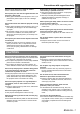
Important Information Precautions with regard to safety WARNINGS If you notice smoke, strange smells or noise coming from the projector, disconnect the mains plug from the mains socket. Do not continue to use the projector in such cases, otherwise fire or electric shocks could result. Check that no more smoke is coming out, and then contact an Authorised Service Centre for repairs. Do not attempt to repair the projector yourself, as this can be dangerous.
Do not use the projector in a bath or shower. Fire or electric shocks can result. Do not place your skin into the light beam while the projector is being used. Strong light is emitted from the projector’s lens. If you place directly into this light, it can hurt or damage your skin. Do not look into the lens while the projector is being used. Strong light is emitted from the projector’s lens. If you look directly into this light, it can hurt and damage your eyes.
Important Information Precautions with regard to safety Do not mix old and new batteries. If the batteries are inserted incorrectly, they may explode or leak, and fire, injury or contamination of the battery compartment and surrounding area may result. Remove the used batteries from the remote control promptly. If you leave used batteries in the remote control for an extended period of time, it may cause liquid leaking, abnormal internal temperature rising or explosion.
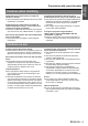
Cautions when installing Avoid setting up in places which are subject to vibration or shocks. The internal parts can be damaged, which may cause malfunctions or accidents. Avoid setting up in places which are subject to sudden temperature changes, such as near an air conditioner or lighting equipment. The life of the lamp may be shortened or the projector may be turned off. See “TEMP indicator” on page 40. Do not set up the projector near high-voltage power lines or near motors.
Important Information Precautions with regard to safety Accessories Make sure the following accessories are provided with your projector. Remote control for PT-AX200E (x1) N2QAYB000194 AA batteries for remote control (x2) Safety cable TTRA0140 Attachment screw (x1) Safety cable (x1) Mains lead for continental Europe (x1) K2CM3FR00002 Lens cover (x1) TKKL5372 Mains lead for UK (x1) K2CT3FR00003 * The protectors for enclosed products, such as a plug cover or foam cartons must be treated properly.
About Your Projector POWER button While the MAIN POWER button is on, switch between stand-by mode and projection mode. (page 19) PICTURE MODE buttons Switch to the best setting for a darker room. Switch to the best setting for a brighter room. Display the FAVOURITE LOAD menu. (page 22) Switch to cycle through the aspect ratio. (page 23) Display the main menu or return to the previous menu. (page 27) Navigate through the menus with FGIH, and activate the menu item with ENTER.
About Your Projector Projector body J Top and front view POWER/LAMP/TEMP indicators (page 19/page 40) Preparation Luminance sensor Senses the luminance for the LIGHT HARMONIZER feature. (page 31) POWER While the MAIN POWER is on, switch between stand-by mode and project mode. (page 19) RETURN Return to the previous menu. (page 27) Control panel INPUT SELECT Switch to cycle through the input method. (page 21) MENU Display the main menu. Return to the previous menu.
About Your Projector J Back and bottom view SERIAL Connect a compatible cable for controlling the projector remotely via your computer. S-VIDEO IN Connect a S-VIDEO signal cable. VIDEO IN Connect an RCA composite video cable. Connecting terminals (page 18/page 46) HDMI IN Connect HDMI signal cables. Preparation COMPUTER IN Connect an RGB signal cable from your PC. COMPONENT IN Connect YPBPR signal cables.
Setting up Screen size and throw distance Projected image SH You can adjust the projection size with 2.0x zoom lens. Calculate and define the throw distance as follows. SD SW Screen Getting Started Projection size (16 : 9) Screen Diagonal (SD) Screen height (SH) Throw distance (L) Screen width (SW) Minimum distance (LW) Maximum distance (LT) 1.02 m (40") 0.50 m (1'7") 0.89 m (2'11") 1.2 m (3'11") 2.4 m 1.27 m (50") 0.62 m (2') 1.11 m (3'7") 1.5 m (4'11") 3.0 m 1.52 m (60") 0.75 m (2'5") 1.
Setting up Projection method You can use the projector with any of the following 4 projection methods. To set the desired method in the projector, See “INSTALLATION” on page 38.
Setting up Lens shift and positioning If the projector is not positioned right in front of the centre of the screen, you can adjust the projected image position by moving the lens shift dials within the shift range of the lens. J Adjusting the lens shift lever 1. Screw the shift lever counterclockwise to unlock. 2. Move the shift lever to adjust the projected image position. 3. Screw the shift lever clockwise to lock.
Setting up J Projector location range You can determine where to locate the screen and the projector by considering the lens shift possibilities. See “Positioning the image” on page 21.
Connections Before connecting to the projector Read and follow the operating and connecting instructions of each peripheral device. The peripheral devices must be turned off. Use cables that match each peripheral device to be connected. Confirm the type of video signals. See “List of compatible signals” on page 45. Audio cables must be connected from each peripheral device directly to the audio reproduction system.
Switching the projector on/off Mains lead J Connecting J Disconnecting 1. Make sure the shape of the mains plug and the AC IN connector on the back of the projector match, then push the plug all the way in. 2. Connect the mains lead to a mains socket. 1. Make sure the MAIN POWER is switched off and unplug the mains lead from the mains socket. 2. Hold the plug and unplug the mains lead from the AC IN connector on the side of the projector. NOTE: • • • • • Do not use other than the provided mains lead.
Switching the projector on/off Switching on the projector POWER indicator 1. Switch the MAIN POWER button on. The power indicator lights up in red. 2. Remove the lens cover from the lens. 3. Press the POWER button. The power indicator lights up in green after flashing for a while. The STARTUP LOGO is displayed on the screen. See “STARTUP LOGO” on page 38.
Projecting an image Selecting the input signal 1. Switch on the connected devices. Press the play button of the required device. 2. Press the INPUT SELECT button to select the required input method if needed. See “Switching the input signal” on page 26. NOTE: • AUTO SEARCH is ON as default and the signal from the connected devices is detected automatically. See “AUTO SEARCH” on page 38. The image will be projected on the screen. Positioning the image 4. Adjust the focus and the projected image size.
Remote control operation Operating range You can operate the projector with the remote control within the remote range 7 m (22'11"). Q Facing to the projector Ensure the remote control emitter is facing to the remote control signal receptor on front/back of the projector and press the required buttons to operate. Q Facing to the screen Ensure the remote control emitter is facing to the screen and press the required buttons to operate the projector. The signal will be reflected off the screen.
Remote control operation Adjusting the image You can display the PICTURE and ADVANCED MENU menu items by pressing the PIC. ADJUST button. Press the button to switch between PICTURE and ADVANCED MENU menu. Press F G to select the required menu item and I H to adjust.
Remote control operation Setting your own colour profile You can adjust a selected colour individually and save and retrieve under the PICTURE MODE setting. Press the COLOR MANAGEMENT button to open the menu. PROFILE NORMAL CURSOR LOG PROFILE SAVE PROFILE DELETE PROFILE NAME CHANGE 3. Select a menu item and the I H to adjust each item level. The result box is displayed on the right of the cursor and shows the adjusted colour.
Remote control operation Q Saving a log setting as a profile Return to the COLOUR MANAGEMENT menu and save the stored log as a profile. Make sure that the PICTURE MODE is not switched. 1. Select the PROFILE SAVE menu and press ENTER The PROFILE SAVE menu is displayed. You can save the profile as USER1, USER2 and USER3. Q Loading saved profiles When profiles are loaded under the PICTURE MODE setting, you can keep them as you defined until the PROFILE is set to NORMAL. 1.
Remote control operation Switching the input signal You can switch the input method manually by pressing the INPUT SELECT button. Press the button several times or press I H to cycle through the input methods as follows. The actual projected image will be changed in a while. The graphical guidance will be displayed on the upper right of the projected image and you can confirm the selected input method which is highlighted in yellow. See “INPUT GUIDE” on page 38.
Menu Navigation The menu system allows you to access functions which do not have their own dedicated buttons on the remote control. The menu options are structured and categorised. You can navigate through the menu with F G H I buttons. Navigating through the MENU J Displaying the main menu Press the MENU button to display the main menu and the operating guidance. Sub-menu 1. Press F G to scroll to the required main menu item and press ENTER to select.
Menu Navigation Main menu and sub-menu The main menu has 5 options. Select the required menu item and press ENTER to display the sub-menu. NOTE: • Some default settings vary by the selected input signal. • Sub-menu items vary according to the selected input signal. • Some settings are adjustable without any signals.
Menu Navigation Main menu POSITION Sub-menu H-POSITION V-POSITION DOT CLOCK*1 PHASE*2 CLOCK ASPECT Options (Underlined is default setting) • • • • Page Default: 0 Default: 0 Default: 0 Default: 0 WSS*3 4:3 ZOOM1 H-FIT ON OVER SCAN*4 KEYSTONE • Default: 0 • Default: 0 page 34 page 34 page 34 16:9 ZOOM2 V-FIT OFF 14:9 V SCROLL JUST page 34 page 34 page 36 page 36 page 36 AUTO SETUP*5 page 36 LANGUAGE OPTION BLANK SLEEP FAVOURITE LOAD LIGHT HARMONIZER AUTO SETUP HDMI 1 IN HDMI 2 IN COMPUTER
PICTURE menu Remote control Control panel CONTRAST You can adjust the contrast of the projected image. Adjust the BRIGHTNESS in advance if necessary. Lower See “Navigating through the MENU” on page 27. See “Main menu and sub-menu” on page 28. Setting range: -32 to +32 BRIGHTNESS PICTURE MODE Depending on the projection environment, you can use these preset parameter settings to optimise image projection. Press I H to cycle through the options.
PICTURE menu COLOUR TEMPERATURE You can adjust the white balance of the projected image. Less reddish Setting range: -6 to +6 DYNAMIC IRIS Automatic adjustment No adjustment The luminance sensor detects the brightness of the room and keeps the luminance in balance automatically. If needed, you can switch this function on/off from MODE, or adjust it manually from MANUAL by pressing I H.
PICTURE menu J TV-SYSTEM When the video signal is changed, the setting switches automatically. You can switch the setting manually to match the video data. Press I H to cycle through the options. AUTO NTSC SECAM NTSC 4.43 PAL-N PAL-M PAL NOTE: • AUTO setting will select from NTSC/NTSC 4.43/PAL/ PAL60/PAL-M/PAL-N/SECAM. FAVOURITE SAVE You can save and name the adjusted PICTURE menu settings for instant access from FAVOURITE LOAD menu. 1. Adjust the items in PICTURE menu. 2.
PICTURE menu FAVOURITE EDIT SIGNAL MODE You can edit the named memory settings. Q Deleting a memory setting 1. Select FAVOURITE DELETE and press the ENTER button. 2. Select the required memory setting and press the ENTER button. The current selected signal will be displayed. This is available with signals from COMPUTER IN/ COMPONENT IN/HDMI IN only. NOTE: • See “List of compatible signals” on page 45. If you select ALL DELETE, you can delete all of the saved memory settings. 3.
POSITION menu Remote control Control panel CLOCK PHASE If you require further adjustment for the same reason as the DOT CLOCK adjustment, you can fine adjust the timing of the clock. Press I H to adjust. (Available with signals from COMPUTER IN/COMPONENT IN only) See “Navigating through the MENU” on page 27. See “Main menu and sub-menu” on page 28. H-POSITION You can move the projected image horizontally for fine adjustment.
POSITION menu J Aspect ratio options and projection example If you apply the aspect ratio options to the projected image, the result will be as follows. The result may differ due to the input signals. See “Switching the aspect ratio” on page 23. Q VIDEO/S-VIDEO/COMPONENT Not available with 1 125 (1 080)/50i, 1 125 (1 080)/60i, 1 125 (1 080)/50p, 1 125 (1 080)/60p, 1 125 (1 080)/ 24p, 750 (720)/50p and 750 (720)/60p signals. 4:3 Squeeze signal 16:9 Letter box 14:9 Letter Box 2.
POSITION menu WSS KEYSTONE WSS (Wide Screen Signalling) detects if a PAL/ 625p (576p)/625i (576i) signal is input and that signal has an identification signal, and switch the aspect ratio to required setting automatically. You can switch the system off manually. If the projector is aligned non-perpendicularly to the screen, or if the projection screen has an angled surface, you can vertically correct keystone.
FUNCTION BUTTON Remote control Control panel See “Navigating through the MENU” on page 27. See “Main menu and sub-menu” on page 28. FUNCTION BUTTON You can assign a frequently used menu option to the FUNCTION button for shortcut. Press I H to select the required menu option and press the ENTER button.
OPTION menu Remote control Control panel BACK COLOUR You can choose a screen colour from BLUE or BLACK for when the projector is idle. Press I H to select. STARTUP LOGO See “Navigating through the MENU” on page 27. See “Main menu and sub-menu” on page 28. INPUT GUIDE ON OFF When you change the input method, the guidance appears in the upper right corner of the screen. The following display methods are available. Press I H to cycle through the options.
OPTION menu SLEEP LAMP RUNTIME You can select the required duration of time and set the off timer to turn off the power of the projector automatically. 3 minutes before turn-off, the countdown of minutes will be displayed in the lower right corner. Press I H to cycle through the options. OFF 240MIN. 60MIN. 210MIN. 90MIN. 180MIN. 120MIN. 150MIN. You can check how long time the lamp has been used. NOTE: • LAMP RUNTIME is a relevant matter for lamp replacement timing.
TEMP and LAMP Indicators Managing the indicated problems If a problem should occur with the projector, the LAMP and/or TEMP indicators will inform you. Manage the indicated problems as follow. 1. Confirm the status of all indicators and projector, and switch off the projector in proper way. 2. Find out the cause of the problem by status of the LAMP and/or TEMP indicators. 3. Follow the following instruction for each indication and solve the problem. 4.
Care and Replacement Cleaning the projector J Before cleaning the projector Switch off the MAIN POWER switch in proper way and disconnect the mains plug from the mains socket. Unplug all the cables from the projector. J Cleaning the outer surface of the projector Wipe off dirt and dust gently with a soft cloth. If it is difficult to remove the dirt, soak a cloth in a neutral detergent diluted with water, wring the cloth well and then wipe the projector. Dry off the projector with dry cloth.
Care and Replacement Replacing the lamp unit J Before replacing the lamp unit Switch off the MAIN POWER button in proper way and disconnect the mains plug from the mains socket. Make sure the lamp unit and the surroundings are cooled enough. Unplug all the cables from the projector. Prepare a Phillips-head screwdriver. Contact an Authorised Service Centre to purchase a replacement lamp unit (ET-LAX100).
Care and Replacement J Removing and replacing the lamp unit 1. Turn the projector upside down and place it gently on a soft cloth. 2. Use a Phillips screw driver to loosen the 2 lamp unit fixing screws until the screws turn freely and remove the lamp unit cover. 3. Use a Phillips screw driver to loosen the 2 lamp unit fixing screws until the screws turn freely. 4. Hold the handle of the lamp unit and pull out gently from the projector. 5.
Troubleshooting Should any problem persist, contact your dealer. Problem Cause Reference page Power does not turn on. The mains lead may not be connected. The MAIN POWER switch is turned off. No electric supply is at the mains socket. TEMP indicator is lit or flashes. LAMP indicator is lit or flashes. The lamp unit cover has not been securely installed. The circuit breakers have tripped. 19 20 19 40 40 42 18 No picture appears.
Technical Information List of compatible signals Signal NTSC/NTSC 4.43/ PAL-M/PAL60 PAL/PAL-N/SECAM 525i (480i) 625i (576i) 525p (480p) 625p (576p) 1 125 (1 080)/60i 1 125 (1 080)/50i 1 125 (1 080)/24p 1 125 (1 080)/60p 1 125 (1 080)/50p 750 (720)/60p 750 (720)/50p VGA480 WIDE480 SVGA WIDE600 WIDE720 XGA WIDE768 MXGA SXGA SXGA60+ WIDE768-2 Display mode Display resolution (dots)*1 Scanning frequency H (kHz) V (Hz) Dot clock frequency (MHz) Picture quality*2 - 720 x 480i 15.7 59.
Technical Information Serial terminal The serial connector which is on the connector panel of the projector conforms to the RS-232C interface specification, so that the projector can be controlled by a personal computer which is connected to this connecter. J Connection D-sub 8 pin (male) Computer Serial terminal adapter (ET-ADSER: Optional) Serial terminal (female) NOTE: • You must use only an RS-232C Serial Interface Cable with a ferrite core, type ET-ADSER.
Technical Information J Communication settings Signal level RS-232C Sync. method Baud rate Parity Character length 8 bits Stop bit 1 bit 9 600 bps X parameter None None S parameter None Asynchronous J Control commands Command Control contents Remarks PON POWER ON In standby mode, all commands other than the PON command are ignored. The PON command is ignored during lamp ON control.
Technical Information Specifications Power supply AC 100 - 240 V 50 Hz/60 Hz Power consumption 290 W During standby (when fan is stopped): 0.08 W Amps 3.5 A - 1.5 A LCD panel Panel size (diagonal) 0.7 type (17.78 mm) Aspect ratio 16 : 9 Display method 3 transparent LCD panels (RGB) Drive method Active matrix method Pixels 921 600 (1 280 x 720) x 3 panels Lens Manual zoom (2x)/Manual focus F 1.9 - 3.1, f 21.7 mm - 43.
Technical Information S-VIDEO IN Single - line, Mini DIN 4p Y: 1.0 V [p-p], C: 0.286 V [p-p], 75 Ω VIDEO IN Single - line, RCA pin jack1.0 V [p-p], 75Ω Single - line, D - sub HD 15-pin (female) COMPUTER IN R.G.B. 0.7 V [p-p], 75 Ω G.SYNC 1.0 V [p-p], 75 Ω HD/SYNC TTL high impedance, automatic positive/negative polarity compatible VD TTL high impedance, automatic positive/negative polarity compatible Y, PB/CB, PR/CR Single - line, RCA pin jack x 3 Y: 1.
Technical Information Ceiling mount bracket safeguards The projector and the ceiling mount bracket are designed sufficiently safety though, make sure the safety cable provided with the projector is installed and attached to the security lock slot of the projector when mounting in the ceiling for safety and security.
Technical Information Dimensions 102.5 (4-1/32) 112 (4-13/32) 121 (4-3/4) 69 (2-11/16) 300 (11-5/8) 271.1 (10-21/32) Unit: mm 395 (15-17/32) Trademark acknowledgements These Operating Instructions are printed on recycled paper. Appendix VGA and XGA are trademarks of International Business Machines Corporation. S-VGA is a registered trademark of the Video Electronics Standards Association.
Index A F AC IN ......................................................................13 Accessories ..............................................................10 ADVANCED MENU ...................................................31 Air exhaust port ........................................................12 Air filter ....................................................................13 Replacing ...........................................................41 Air intake port ...............................
Index S MAIN POWER ..........................................................13 Mains lead Accessory ..........................................................10 Connecting .........................................................19 MENU Control panel button ............................................12 Remote control button .........................................11 Remote control function .......................................27 Menu Main menu .........................................................
Matsushita Electric Industrial Co., Ltd. Web Site: http://panasonic.net © 2007 Matsushita Electric Industrial Co., Ltd. All Rights Reserved.