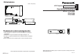
Dimensions R LCD Projector Commercial Use 297(11-11/16) 7(1/4) 81.2(3-3/16) Model No. PT-LC80E PT-LC76E PT-LC56E 72(2-13/16) 41.8 (1-5/8) 209(8-7/32) Operating Instructions 195(7-21/32) POWER INPUT VIDEO AUTO SETUP Trademark acknowledgements ENTER SHUTTER FREEZE STD VOLUME B VGA and XGA are trademarks of International Business Machines Corporation. B Macintosh is a registered trademark of Apple Computer, Inc.
IMPORTANT: THE MOULDED PLUG (U.K. only) This instruction booklet provides all the necessary operating information that you might require. We hope it will help you to get the most performance out of your new product, and that you will be pleased with your Panasonic LCD projector. The serial number of your product may be found on its bottom. You should note it in the space provided below and retain this booklet in case service is required. FOR YOUR SAFETY, PLEASE READ THE FOLLOWING TEXT CAREFULLY.
Preparation IMPORTANT SAFETY NOTICE ...2 Precautions with regard to safety .........................................5 Accessories .................................9 Before use ..................................10 Location and function of each part...........................................12 Getting started Setting-up...................................17 Projection methods, Projector position, Projection distances Connections...............................
6-ENGLISH During a thunderstorm, do not touch the projector or the cable. B Electric shocks can result. Do not use the projector in a bath or shower. B Fire or electric shocks can result. Do not look into the lens while the projector is being used. B Strong light is emitted from the projector’s lens. If you look directly into this light, it can hurt and damage your eyes. B Be especially careful not to let young children look into the lens.
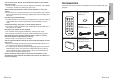
8-ENGLISH Accessories Check that all of the accessories shown below have been included with your projector. Card remote control unit Lithium battery for (TNQE239 x1) remote control unit (CR2025 x1) POWER RGB signal cable [3.0 m (9´10˝), K1HA15FA0002 x1] INPUT VIDEO AUTO SETUP RGB MENU ENTER FREEZE SHUTTER STD VOLUME Video/Audio cable [3.0 m (9´10˝), K2KA2FA00001 x 1] Mains lead for U.K. (TXFSX02PTFZ x 1) D.
Before use Be sure to attach the lens cover before moving the projector. The projection lens is extremely susceptible to vibration and shocks. When moving the projector, use the accessory carrying bag. When placing the projector inside the carrying bag, position it so that the lens is facing upward. Cautions regarding setting-up Avoid setting up in places which are subject to vibration or shocks. The internal parts can be damaged, which may cause malfunctions or accidents.
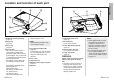
Projector # Projector $ % ' $ # + & * ' ) # Projector control panel(Top) (page 14) $ Zoom ring (page 23) % Focus ring (page 23) & Security lock This can be used to connect a commercially-available theftprevention cable (manufactured by Kensington). This security lock is compatible with the Microsaver Security System from Kensington. Contact details for this company are given below. Kensington Technology Group ACCO Brands Inc.
Menu operation # $ % & ' ( * ) +, Remote control unit ' ) POWER ( INPUT VIDEO RGB * + AUTO SETUP MENU , ENTER . / FREEZE SHUTTER 0 STD VOLUME D.ZOOM INDEX WINDOW 1 # RGB INPUT indicator (page 25) This indicator shows whether a signal is being input to the RGB input connectors (RGB 1 IN/RGB 2 IN). When an input signal is detected, the indicator illuminates.
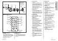
Setting-up Connector panel Projection methods How to open FRE IND WIN EX DO W STD EZE OO AUT SET O UP D.Z EN M TTE PO WE TER SHU - R R VID ME EO NU B $ # MAIN POWER switch (pages 22 and 24) $ Power input socket (AC IN) (page 22) The accessory mains lead is connected here. Do not use any mains lead other than the accessory mains lead.
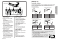
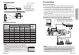
SH Top edge of screen Screen L: Projection distance SH: Image height SW:Image width H1: Distance from centre of lens to bottom edge of projected image H1 L 81.2 (3-3/16) Bottom edge of screen SW L Connections Notes on connections B Read the instruction manual for each system component carefully before connecting it. B Turn off the power supply for all components before making any connections.
Monitor Computer Computer for control use Preparation for the remote control unit Insert the lithium battery which is supplied with the remote control unit, making sure that the polarities are correct. # While pushing the battery holder tab to the right, pull out the battery holder. Back side Push the tab RGB signal cable Pull out $ Insert the battery into the battery holder so that the + side is facing upward.
Turning on the power VIDEO Input select buttons # $ INPUT Mains lead Changing signals RGB & AUTO SETUP RGB2 VIDEO RGB1 S-VIDEO VIDEO S-VIDEO RGB2 ) SHUTTER STD D.ZOOM * ( INDEX WINDOW PROJECTOR Lens cover Follow the procedure below when you set the projector up first, and when you change the setup place. ' Adjusting the angle ( Press the AUTO SETUP button to initiate automatic positioning. ' the MAIN POWER switch to turn on the # Press power.
Turning off the power RGB input indicator Power indicator # POWER INPUT VIDEO AUTO SETUP RGB MENU ENTER $ SHUTTER STD VOLUME D.ZOOM INDEX WINDOW PROJECTOR NOTE: B You can also turn off the power by pressing the POWER button twice or by holding down it for at least 0.5 seconds. B When the projector is in standby mode (the power indicator on the projector is illuminated red), the projector will still draw a maximum 3 W of power, even when the cooling fan has stopped.
Correcting keystone distortion and automatic positioning (AUTO SET UP) Turning off the picture and sound momentarily (SHUTTER) This projector detects its degree of tilt and the input signal. Keystone distortion and the position of the image can then be corrected automatically in accordance with the input signal. Press the AUTO SETUP button.
Enlarging the picture (D.ZOOM) POWER VIDEO This function lets you store a picture which is being projected into memory, so that you can display a still picture and a moving picture on the screen. Press the INDEX WINDOW button. B The aspect ratio of the screen changes and the image is vertically elongated in comparison to a normal image. Press a D.ZOOM +/- button.
On-screen menus Menu screens The various settings and adjustments for this projector can be carried out by selecting the operations from on-screen menus. The general arrangement of these menus is shown below. MENU KEYSTONE PICTURE POSITION INDEX WINDOW SHUTTER VOLUME LANGUAGE OPTION1 OPTION2 SECURITY SELECT ENTER PICTURE menu (page 35) When an RGB signal is being input EXIT PICTURE PICTURE MODE STANDARD CONTRAST 32 BRIGHT 32 SHARPNESS 0 COLOR TEMP.
POWER INPUT VIDEO AUTO SETUP RGB MENU ENTER SHUTTER FREEZE STD VOLUME D.ZOOM & Press the F or G buttons to select an item, and then press the I or H buttons to change or adjust the setting. An individual adjustment screen such as the one shown below will be displayed for bar-scale items. # Press the MENU button. The MAIN MENU MENU screen will be KEYSTONE displayed.
Keystone distortion is corrected automatically when the projector’s automatic setup function is used, but this correction will not apply if the screen itself is tilted. In such cases, you can correct the keystone distortion manually with the following procedure. For PT-LC76E/PT-LC56E (Vertical keystone distortion correction only) KEYSTONE 0 Vertical keystone distortion correction Operation Press the H button. Press the I button.
This adjusts the darker areas (black areas) in the picture. Press the H button if dark areas are too solid (for example, if hair is difficult to see), and press the I button if black areas are too light (grey rather than black). COLOR TV-SYSTEM ON To reduce flickering of still images (vertical flicker), set "STILL MODE" to “ON” by pressing the I or H buttons. (NTSC/NTSC 4.43/YPBPR only) This adjusts the flesh tones in the picture.
Adjusting the position Use the F and G buttons on the projector or remote control unit to select an item, and then use the I and H buttons to change the setting for that item. For items with bar scales, press the ENTER button or the I or H buttons to display the adjustment screen, and then use the I or H buttons to make the adjustment.
40-ENGLISH RESIZING This should normally be set to “ON”. (This setting is only for signals which have lower resolutions than the LCD panels. Refer to page 58 for details.) ON The pixel resolution of the input signal is converted to the same resolution as the LCD panels before being projected. For signals with lower resolutions, gaps in the pixels are automatically interpolated into the picture before it is projected. This may sometimes cause problems with the quality of the picture.
Use the F and G buttons on the projector or remote control unit to select an item, then press the I or H buttons to change the setting. OPTION1 OSD ON AUTO SIGNAL ON AUTO KEYSTN ON AUTO RGB IN ON RGB2 SELECT INPUT AUTO RGB/YPB PR VGA60/525P 525P SXGA MODE SXGA BLACKBOARD OFF SELECT ADJ RETRN OPTION2 BACK COLOR BLUE FRONT/REAR FRONT DESK/CEILING DESK FAN CONTROL STANDARD LAMP POWER HIGH LAMP RUNTIME 100H FUNC 1 INDEX CONTROL KEY ON AUTO POW.
LAMP RUNTIME This setting displays the usage time for the lamp unit which is currently being used. NOTE: B The lamp’s operating life varies depending on the usage conditions (such as the LAMP POWER setting and the number of times the power is turned on and off). FUNC 1 FUNC1 INDEX [ KEYSTONE This assigns a function to the FUNC1 button of the ET-RM200 wireless remote control unit (sold separately). INDEX Functions in the same way as the INDEX WINDOW button on the accessory card remote control unit.
NOTE: B The entered password will appear as . It will not be displayed on the screen. B If you enter the wrong password, the letters “PASSWORD” and “NEW” will become red. Enter the correct password again. TEXT DISPLAY The setup letters can be displayed at the bottom of the projected image while an image is projected. ON TEXT DISPLAY is enabled. OFF TEXT DISPLAY is disabled.
Cleaning and replacing the air filter If the air filter becomes clogged with dust, the internal temperature of the projector will rise, the TEMP indicator will flash and the projector power will turn off. The air filter should be cleaned every 100 hours of use, depending on the location where the projector is being used. LAMP indicator Indicator display Illuminated (red) It is nearly time to Problem replace the lamp unit. Flashing (red) An abnormality has been detected in the lamp circuit.
Replacing the lamp unit When replacing the lamp, allow it to cool for at least one hour before handling it. B The lamp cover gets very hot, and contact with it can cause burns. Notes on replacing the lamp unit B The light generating lamp is made of glass, so dropping it or allowing it to hit hard objects may cause it to burst. Be careful when handling the lamp. B After having removed the old lamp, carelessly discarding it can cause the lamp to burst.
NOTE: B Be sure to install the lamp unit and the lamp unit cover securely. If they are not securely installed, it may cause the protection circuit to operate so that the power cannot be turned on. ( Insert the mains lead plug into the mains socket and then press the MAIN POWER switch.
Cleaning and maintenance Before carrying out cleaning and maintenance, be sure to disconnect the mains lead plug from the mains socket. Wipe the cabinet with a soft, dry cloth. If the cabinet is particularly dirty, soak the cloth in water with a small amount of neutral detergent in it, squeeze the cloth very well, and then wipe the cabinet. After cleaning, wipe the cabinet dry with a dry cloth. If using a chemically-treated cloth, read the instructions supplied with the cloth before use.
Power supply: Power consumption: 100 V–240 V ~, 50 Hz/60 Hz 220 W (During standby (when fan is stopped): Approx. 3 W) 2.5 A–1.0 A Amps: LCD panel: Panel size (diagonal): 0.7 type (17.78 mm) Aspect ratio: 4:3 (16:9 compatible) Micro lens array: PT-LC80E/PT-LC76E: Available PT-LC56E: Not available Display method: 3 transparent LCD panels (RGB) Drive method: Active matrix method Pixels: PT-LC80E/PT-LC76E: 786 432 (1 024 x 768) x 3 panels PT-LC56E: 480 000 (800 x 600) x 3 panels Lens: Manual zoom (1 - 1.
Appendix Connector pin wiring List of compatible signals B The pin layout and signal names for the S-VIDEO IN connector are shown below. Pin No. Signal # $ Earth (Luminance signal) # Earth (Colour signal) $ Luminance signal % % & External view Colour signal & VGA480 *4 SVGA *4 MAC16 XGA *4 MXGA MAC21 MSXGA *4 SXGA *4 UXGA *4 *4 720 x 480i 15.734 59.
Using the SERIAL connector Connection Communications settings Computer SERIAL(female) DIN 8-pin (male) Serial adapter (ET-ADSER : sold separately) You must use only RS-232C Serial Interface Cable with ferrite core, type ET-ADSER. Pin layout and signal names for SERIAL connector Signal level Sync.
Dimensions R LCD Projector Commercial Use 297(11-11/16) 7(1/4) 81.2(3-3/16) Model No. PT-LC80E PT-LC76E PT-LC56E 72(2-13/16) 41.8 (1-5/8) 209(8-7/32) Operating Instructions 195(7-21/32) POWER INPUT VIDEO AUTO SETUP Trademark acknowledgements ENTER SHUTTER FREEZE STD VOLUME B VGA and XGA are trademarks of International Business Machines Corporation. B Macintosh is a registered trademark of Apple Computer, Inc.