AV ControlStereoReceiver SA-AX730 SA-AX530 Operating Instructions i The photographs show SA-AX730 Before connecting, operating or adjusting this product, please read these instructions completely Please save this manual RQT4731 -P
Dear Customer Thank you for purchasing this product. For optimum performance and safety, instructions carefully. please read These operating instructions are applicable to models / SA-AX730 and SA-AX530, however, ere intended primarily for model SA-AX730. J these Tableof contents User memo: DATE OF PURCHASE DEALER NAME DEALER ADDRESS Precautions ........................................................................ 3 Supplied accessories .......................................................
I Precautions Before using this unit please read these operating instructions carefully. Take special care to follow the warnings indicated on the unit itself as well as the safety suggestions listed below. Afterwards keep them handy for future reference, 1. Power Source--The unit should be connected to power supply only of the type described in the operating instructions or as marked on the unit.
I Supplied accessories[] Please check and identify the supplied accessories. (RJA0065-A) • * * • • ° • • • ° (RSA0Ol0) o • ° .°° • ° • • • * • • • • • • ° [] _ AC power supply cord ..................................................... 1 pc. [] _ AM loop antenna set • AM loop antenna .......................................................... 1 pc. • AM loop antenna holder .............................................. 1 pc. • Screw ...........................................
I Surroundguide You are able to enjoy these two surround systems with this receiver. Dolby Pro Logic is a decoding system that was developed to get a better sense of presence from sources encoded with Dolby Surround. The feeling of position has been improved by the addition of a separate center speaker channel. Dolby Surround was developed to allow enjoyment of Dolby Stereo, a cinema system, in private homes.
I Frontpanel controls I Main unit No. I Name Ref.page (D Power "6/i" switch (POWER, L_/i)...................................................... 16 Press to switch the unit from on to standby mode or vice versa, in standby mode, the unit is still consuming a small amount of power. (_) Sound mode selector/indicators ...................... ® SFC mode selector (MODE) .............................. _) Input indicators ..................................................
I Front panel controls I Remoteconlrol No. Name Ref.page O Power button ( 6 ) .............................................. 31 (_) • button ( • ) ...................................................... 32 (_) _
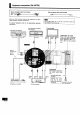
I Equipmentconnections(SA-AX730) Stereo connection cable (not Included) White Red Video connection cable (not included) (L) _ (R) (,aa=_= Make sure that the power supply for all components has been turned off before making any connections. To connect equipment, instructions. refer to the appropriate operating Do not place books, etc., on the top of this unit or block the heat radiation vents in any way.
Monaural connection cable (notIncluded) 6channel discrete Optical fibercable (notincluded) connection enables you to enjoy the sound field effects recorded on DVDs. ............. ...... ,OO gg If your DVD player doesn't have surround decoders Obtain a separately available digital surround processor.
I Equipmentconnections(SA-AX530) Stereo connection cable (not included) White (L) Red (R)_I_=m. ] Video connection cable (not included) Make sure that the power supply for all components has been turned off before making any connections, To connect equipment, instructions. refer to the appropriate Tape deck (not included) PLAY (OUT) operating Do not place books, etc., on the top of this unit or block the heat radiationvents in any way.
Monaural connection cable (not Included) Optical fiber cable (not included) _Lltd 6 channel discrete connection enables you to enjoy the sound field effects recorded on DVDs, If your DVD player doesn't have surround decoders Obtain a separately available digital surround processor.
i -_ Antenna connecllons FM indoor antenna (notineluded) This antenna {s norma{{y sufficient for reception ot FM broadcasts. Attach to a wall (using tape) facing reception. in the direction of best For best receptlen An FM outdoor antenna is recommended, / • _ o'e [] This antenna is normally sufficient for reception of AM broadcasts.
I Antenna connections u FM outdoor antenna s(not included _ H m.o [] An outdoor antenna should be used when mountainous areas or in spaces enclosed by where the FM indoor antenna (included) satisfactory reception. Disconnect the FM indoor antenna if an FM installed. 75 Q coaxial cable not included) Remove a piece outer vinyl insulator. @ • using this unit in reinforced concrete does not provide outdoor antenna is of the 20 mm (25132") Twist the shield braid to expose the core wire.
I Speaker connections Front speaker (Left) (not included) Center speaker (not=included) _ Front Place Front speaker (Right) (not included) speakers the front speakers ear height sound. so there on the left and right of the TV at seated is good coherency between the picture and Center speaker Place this speaker underneath or above the center of the TV. Aim the speaker at the seating area.
Other speakers ] Surround speaker (Right) (not included) Surround speaker (Leff)(notincluded) (notincluded) f Speaker cable (notincluded) \ / O@ _,= --._........ 0 @ 0 © O_ O@ o@ ©0© © 0 _ © @ _ @© _v oo© S Subwoofer with built-in amplifier (not included) f Speaker cables (not included) INPUT .................. Power Amplifier (not included) .'".P.uz. i Monaural-Stereo converter cable (not included) (Connect to the L or R terminal if a monaural cable is used.
I Basic operations Before operation, set VOLUME to the "MIN" position. [] Press, [POWER]. Iml = © o c_3 o ci3_ I Press j@@@ [A] and/or [B] to select the speaker system(s) to be used. A and B refer to the speaker terminals at the rear of the unit. Press [SPEAKERS] and check the "SPEAKERS" indication lights up. if the button is pressed once more, the indicator will switch off and no sound will be heard from the speakers.
I Basicoperations I When usingspeakersunder 8 Q _ [] I Press and hold [A] or [B] until "LOW IMP" lights up on the di_splay. If even one of the speakers being used has an impedance 8 _, press and hold down either button A or seconds or more to set the impedance to LOW. button under B for 4 ]Pressandholddown onceagainfor4 secondsor moreto turnit off.) Note that when "LOW IMP" is iUuminated, speakers [] and [] cannot bothbe used at the same time. TO change e speaker: e.g.
I Listeningto radio broadcasts Use the tuning buttons to tune-in radio stations. _1 Turn [INPUT SELECTOR] to select "TUNER". [] Press [BAND] to select "FM" or "AM". • _1 Press FUNING ('X/) or (/k,)] to tune to the desired frequency. "QUARTZLOCK"lightsup whentuned, "S'I*EREO" lights up when an FM stereo broadcastis received.
I Listeningto radio broadcasts Specify the frequency using the numeric buttons on the remote control to directly tune to the desired station. [] Press [TUNER/BAND]. This will set the remote control to operate the tuner. The selector on the receiver will change to "TUNER". Each time the button is pressed, the band will change follows, FM *_ as AM, [] Press [DIRECT TUNING/DISC ENTER]. ] While cursordisplay isflashing(approx.10 seconds) Press the numeric buttons to enter the frequency.
I Listeningto radio broadcasts Presetting radio stations into the memory channels of this unit makes selecting stations simple, A total of 30 FM and AM stations can be preset. Please remember this If a new broadcast station is preset into a channel, the setting for the broadcast station which was previously entered in that channel will be automatically erased.
I Listeningto radio broadcasts I Manual memory presetting [] I The desired stations can be preset into the desired channels by the user. IT set to the desired frequency. (,,_ Page1B-19.) If interference or static is keeping you from enjoying an FM broadCast, press [FM MODE] and change to monaural. You can preset the station in monaural lust as in stereo. [] Press [MEMORY]. To cancelthe memoryfunction,press[MEMORY]again. [] Press [TUNING (_/) or (/_ )] to select the desired channel.
I ° ° ° ° ° ° ° O Dolby Pro Logic • When reacly to adjust speaker output level, situate yourself where you would normally be listening. • First turn ON the speakers with [SPEAKERS A (or SPEAKERS)[ on the receiver• • If front speaker volume is unbalanced, adjust the balance with [BALANCE]. Ensure the front speakers are connected to the A terminals when you use_olby Pro Logic• The Dolby Pro Logic modes cannot be turned on it "SPEAKERS B" is selected.
I Dolby Pro Logic ] _ e- • • • • Press [TEST] to output a test signal. The speaker outputting the test signal is displayed while the test is running. L : Front speaker (Left] C :Center speaker R : Front speaker (Right] S : Surround speakers The subwoofer is muted while testing. In the PHANTOM mode, the center speaker is OFF, so there is no center test signal and "C" is not displayed. ] iL_,Vnl.
I Dolby Pro Logic Iilililllill'.lillil,I liilli,J,niill,.lll il Ileli I I I illiil _i Adjust the s()und from the surround speakers until the proper effect is produced. Im Turn the sound mode selector to select "SURROUND". IP_ Press [DELAY TIME] to set the time• When the button is pressed, the current delay time is displayed. Each time the button is pressed, the delay time will increase by 5 ms within a range of 15 ms to 30 ms. The standard setting is 20 ms.
I Oolby Pro Logic • [] • " • D• _:[_:[e) Turn [INPUT SELECTOR] to select and start the desired source. ]Turn the sound mode selector to select "SURROUND"or"3STEREO", _ .... When employing SURROUND, Dotby Surround • ................ use software recorded in ,............ For your'reference You can set the Dolby Pro Logic mode for each source Each source will retain the selected mode To turn off the Dolby Pro Logic systems Turn the sound mode selector (_) to select "STEREO". INPUT • ° .
i SFC(SoundField Conh'ol) The SFC function gives presence and spread thereby enhancing and enriching the music or movie. Read the foflowing explanations in order to better understand how to make your.selection. The center speaker is not used in the hall, and simulated modes. HALL This mode imparts e reflection and spread which will make you feel as if you are in a large concert hall. CLUB Like a jazz club, this mode provides an exciting and intimate atmosphere.
I SFC(SoundField Control) With this unit, you can adjust speaker volume, Adjust the field of sound while listening to a source. [ To adjust the volume of the center and surround speakers [] *ITJ _ _! nT*l |=J[_(i] *|1_*]1[*] ] iII Press [LEVEL] to select the center or surround speakers. You can adjust the center speaker volume only in the theater mode. [] Press [+] or [-] to adjust the output level. I ToadjustIhe delaytime [] ] LEVEL Press [DELAY TIME] to set the time.
I DVD 6CH INPUTmode This receiver can playback 6 channel discrete sound. it has terminals for connecting to a component with 6 channel discrete output, such as a DVD player. F.©O o o o o o o o o © ©© : 6 channel discrete output makes playback sound more real by adding depth, movement, position and other characteristics to the field of sound. It will make you feel as if you were at the movie theater when in your own home.
i Other functions .l 4E J m Turn [BASS] to adjust the low frequency sound• Turn [TREBLE] to adjust the high frequency sound• Turn [BALANCE] to adjust the left/right sound balance, ,L,L,L_ I_1 Press [MUTING], The message "MUTING ON NOW"runs repeatedlyfrom right to left across the display as long as the mutingfunction is on. Press once again to return to the previous volume level. When the receiver is turned off, the muting operation will be automatically cancelled.
I Making a recording Before recording, prepare the tape deck for recording. See the tape-deck's operating instructionsfor details. [] Turn [INPUT SELECTOR] to select the source to be recorded. Any sourcecan beselectedexceptTAPE, [] Begin recording on the tape deck. Follow your tape deck's operating instructions. !_! Begin the source to be recorded. Follow your equipment's operating instructions. INPUT SELEC_Ro_ To check Ihe sound recorded while a recording is being made [] .
n using the remote control Point the remote control toward the receiver Basic operations TUNER/ BAND Once the unit has been set to ON, it can be turned ON and OFF simply by pressing To turn the unit ON/OFF After turning the TV, VCR or DVD player ON or OFF, always press ! TUNER/BAND before pressing [ _ ] when turning the receiver ON and OFF.
I Usingthe remote control Make sure the remote control is in the tuner operation mode, (,_ Page 31,) I Point the remote control toward the receiver To listen to radio broadcasts To select "FM" or "AM" TUNER/ (_ To select the desired channel sequentially Presettuning) (_c 1 To select the desired Change as follows pressed.
Turn the CD changer (or CD player] ON before trying to operate it by remote control. Make sure the remote control is in the CD player operation mode. (m) Page 31,) It may not be possible to operate some CD players with this unit. Point the remote control toward the CD changer (or CD player) To start play 0 For 5 CD changer (_ I_ For MEGA • TAPE CD TITLE TUNER/ Select disc number. CD changer ._ ,,6 [CD changeronly] To start play from the desired disc © Select the disc number.
Using the remote control I _m The procedure below are examples for when a TV and VCR are connected to the receiver as shown in this manual. This remote control transmitter is designed for home theater system, if you press [TV] (or [VCR]) and [ _ ] in succession, the TV (or VCR) and receiver will be turned on and the selector on the receiver will change to TV/DSS (or VCR). Press [ (_ ] within 3 seconds of pressing [TV] (or [VCR]).
The procedures below are examples for when a TV and VCR are connected To watch video tapes Point the remote control toward the TV and the receiver TV C) to the receiver as shown in this manual. 6 ,,I. 0 Point the remote control toward the VCR player and the receiver -_ Switch ON the TV and the receiver. VCR 0 Point the remote control towardtheTV d) TVNIDEO -_ (Z_)-I, Switch ° ON VCR player, 0 the ,, Set the W/VIDEO mode on the TV to "VIDEO".
I Using the remote control The procedures below are examples for when a TV and DVD player are connected to the receiver as shown in this manual. Make sure the remote control is in the DVD player operation mode. (,._ Page 31.) Actual operations depend on your equipment and software.
Change the remote control code in either of the following circumstances: • If the Penasonic TV or VCR does not operate as a result of a difference in the remote corltrol code. • If you wish to operate some other make of TV or VCR. (Refer to pages 34, 35 for the buttons which can be operated.) How to change 11/ the remote code Hold down the button corresponding to the component you wish to operate. VCR CDCD • control TAPE Continue to hold the button down and...
I About the HELPfunction J tf you make a mistake in operation or if sound output stops due to some operation which was performed, the HELP function displays information which can he useful for indicating the method by which this conditiorTcan be remedied. It "ERROR" or scrolling characters (for instance, "SPEAKER OFF NOW") appear on the display during operation, carry out the following operation. Press [-HELP/-RESET]. The methodforremedyingthis situationwill be displayed. E3.
I Troubleshootingguide For detailed instructions, contact an authorized servlcenter in the U.S.A. and Panasonic Canada Inc. Customer Care Centre in Canada. In the U.S.A. 1-800-211-7262 or web site (http://www.panasonlc.oorn) In Canada 905-824.5505 or web site (www.panasonic.ca/faq.html) Before requesting service for this unit, check the chart below for a possible cause of the problem you are experiencing.
I Technicalspecifications(iHF'78) • AMPLIFIER SECTION Rated minimum sine wave RMS power output 40 Hz-20 kHz both channels driven 0.8% total harmonic distortion • 80 W per channel (8 _) 1 kHz continuouspoweroutput both channelsdriven 0.05% total harmonicdistortion 83 W perchannel(8 _) Total harmonic distortion rated power at 40 Hz-20 kHz half power at 1 kHz Power output at the Dolby Pro Logic operation 0.