AV ControlStereoReceiver SA-EX320 Operating ! Instructions
User memo: Dear Customer Thank you for purchasing For optimum instructions performance this Technics and safety, DATEOFPURCHASF product. please DEALER NAME read these carefully. DEALER ADDRESS TELEPHONE Tableof contents NUMBER The model number and serial number of this product can be found on either the back or the bottom of the unit. Precautions.................................................................................. 3 Supplied accessories............................................
Before usingthisunitplease readtheseoperating instructions carefully:. Takespecial caretofollow the warnings indicated on the unit itself as well as the safety suggestions listed below. Afterwards keep them handy for future reference. or as 1. Ventilation - The unit should be situated so that its location or position does not interfere with its proper ventilation.
Please check and identify the supplied accessories. (_ AC power supply cord (SJA172) ............................................ 1 pc. (_ AM loop antenna set (RSAO010) • AM loop antenna ................................................................. 1 pc. • AM loop antenna holder ...................................................... • Screw .................................................................................. 1 pc. 1 pc. FM indoor antenna (RSAO006) .................................
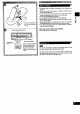
[] • Thoroughly clean the battery compartment before inseding new batteries. • Do not mix old and new batteries, or batteries of different types (carbon and alkaline, etc.). • If you will not use the remote control for a long period of time, remove the batteries and store them in a cool, dark place. • Do not use rechargeable type batteries. • Do not attempt to recharge alkaline or carbon batteries.
(_) Power "STANDBY IO/ON" switch (POWER, STANDBY _)/ON) Press to switch the unit from on to standby mode or vice versa. In standby mode, the unit is still consuming a small amount of power.
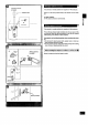
Make sure that the Power supply for all components has been turned off before making any connections. .. • : .... _ To connect equipment, : '!_. _, :: ..... refer to the appropriate operating instructions. Do not place books, etc., on the top of this unit or block the heat radiation vents in any way.
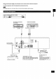
(L) _ I White Stereo Red connect!on (R) cable (not included) __ Video connection cable (not included) TV (not included) AUDIO ,_ OUT OUT VIDEO IN / @ @ To connect DVD player TV DVD player (not included) AUDIO AUDIO IN OUT (not included) VIDEO "-"' OUT I -_-': t/OlefOR I VCR (not included) AUDIO VIDEO I J I Iv_DEO
[] FM indoor antenna This antenna is normally sufficient for reception of FM broadcasts. (included) Attach to a wall (using a tape) facing in the direction of best reception. For best reception An FM outdoorantenna is recommended. q> E This antenna is normally sufficient for reception of AM broadcasts. Fit the AM loop antenna holder (included) onto the rear panel of this unit and then attach the AM loop antenna to the AM loop antenna holder "(facing in the direction of best reception).
[] FM Outdoor antenna (not included) An outdoor antenna should be used when using this unit in mountainous areas or in spaces enclosed by reinforced concrete where 75 .Q coaxial cable I the FM indoor antenna (included) does not provide satisfactory reception. Disconnect the FM indoor antenna if an FM outdoor antenna is installed. (not included) I O Removea pieceof the outer vinylinsulator. i _Z_)"" 201_m_m(25/32") An outdoor only.
Frontspeaker (Left) (notincluded) Center speaker Front speaker (notincluded) (Right) _-i -') (not included) •_ Subwoofer (not included) As well as enjoying normal stereo reproduction with the left and right front speakers, a center speaker and surround speakers can also be connected to this unit in order to enjoy the sound performance of Dolby Pro Logic Systems. We recommend that surround speakers be placed on the side of or slightly behind the listener, and about one meter higher than ear level.
I Centerspeakerand Surroundspeakers " Surround speaker (Right) (not included) I Surround speaker (Left) (not included) 1. Before sound can be heard, both surround speakersmustbe connected. 2. Do not connect the surround speakers to the front speakerterminals.The surroundspeakers may be damagedif connectedto the front terminals. Center speaker (not included) Speaker impedance: Centerspeaker:. 8 Surround_Re,ake_.._8. Q........
Beforeoperation,set VOLUMEto the "MIN" position. !iii _21_ ill Press POWER. I_ Press SPEAKERS and check the "SPEAKERS" indication lights up. !!iiiii!!i o_ - _r O0 If the button is pressed once more, the indicator will switch off and no sound will be heard from the speakers. O; ia fill Press to select the desired source, and start the desired source. (Refer to the appropriate operating instructions for details.) VCRLTo watch video tapes (VCF_" .,' ....................................
[] Turn BASS to adjust the low frequency sound. Turn TREBLE to adjust the high frequency sound. [] Turn BALANCE to adjust the left/right sound balance. [] Press MUTING. The message "MUTING ON NOW" runs repeatedly from right to left across the display as long as the muting function is on. Press once again to return to the previous volume level. _ ['_T_ MIN When the receiver is turned off, the muting operation automatically cancelled. will be [] L (_) Use VOLUME to, reduce the volume level.
[] You can use the tuning buttons to tune-in radio stations. O0 0 B Press TUNER. [] Press BAND to select "FM" or "AM". I_ Press TUNING (V) or (A) to tune to the desired frequency. Tuning intervals TUNER I FM: 0.2 MHz AM: 10 kH:-.. °......... "QUARTZ LOCK" lights up when tuned. "STEREO" lights up when an FM stereo received.
Presetting radio stations into the memory channels makes selecting stations simple. of this unit A total of 30 FM and AM stations can be preset. Please remember this If a new broadcaststationis preset intoa channel,the settingfor the broadcaststationwhichwas previouslyentered in that channel will be automaticallyerased. I Automatic memory presetting -., Automatic memory presetting allows this unit to automatically search for broadcast stations and then preset them into memory.
I Manual memorypresetting [] .. { The desired stations can be preset into the desired channels by the user. E! Set to the desired frequency. (See page 15.) OO oo If interference or static is keeping you from enjoying an FM station, press FM AUTO/MONO and change to monaural. You can preset the memory in monaural just as in stereo. o I1_ Press MEMORY. To cancel the memory function, pr.e._s.MEMORY aga..!n. I_ Press PRESET (V) or (A) to select the desired channel. _. .
Front Center Dolby Pro Logic lets you enjoy movie software (video tapes and laser discs) in your own home with the same powerful stereophonic effect found in movie theaters. This unit has two Dolby Pro Logic modes: SURROUND and 3 STEREO. Front speaker (Left) s.
B I i|vl |:] i l [l| (_illll] Ill |1] [o] i I |vJ Press TEST to output a test signal. The speaker outputting the test signal is displayed while the test is running. L : Front speaker (Left) C : Center speaker R : Front speaker (Right) S : Surround speakers IQc-p For SURROUND L--CNR t _ mode S I In the PHANTOM mode, the center_peake[ is.OFF, so_Ibere is no center test signal and "C" is not displayed.
H !!!!!_!!!!!i Select and start the desired source. B Press DR PRO LOGIC to turn on the Dolby Pro Logic system and select the desired mode. When the button is pressed, the Dolby Pro Logic mode is displayed. Pressing it again changes the Dolby Pro Logic mode. II When employing SURROUNDs. Dolby Surround. use software recorded in _...__.___.--.__o-_____-___=.-__***.________-._._*__....*__..---___..H****_*oI__ For your reference You can set the Dolby Pro Logic mode for each source.
[] Before recording, prepare the tape deck for recording (recording level adjustment, etc.). See the tape deck's operating instructions for details. _1 I"=Ioo O0 0 Select the source to be recorded. Any source can be selected except [TAPE MONITOR 1. F_ Begin recording on the tape deck. Follow your tape deck's operating instructions. [] Begin the desired source to be recorded. Follow your equipment's operating irLstructJons ................
If you make a mistake in operation or if sound output stops due to some operation which was performed, the HELP function displays information which can be useful for indicating the method by which this condition can be remedied. if "ERROR" or scrolling characters (for instance, 'qAPE MONITOR ON NOW") appear on the display during operation, carry out the following operation. Press -HELP. k | == oo I I I I I I (Touch only.) The method for remedying this situation will be displayed.
Thisremote control can be used to operate the receiver you purchased and-some other Panasonic and Technics compact cassette decks, CD • For an explanation on how to set up your remote control and precautions, see page 5. : changers (and CD players), TVs, VCRs and laser disc players, provided they are equipped with the remote control sensor, • For details on operating other equipment, ual provided with the specific unit.
To operate the receiver (continued) To listen to radio broadcasts Facing toward the receiver To switch the remote control transmitter to tuner operation mode TUNER Be sure to press this button before operating the receiver. CD To select the desired vCH O0 To select 666 6665 6666 o6cb! 0000 channel 6666 66cbcb c_ S_ECT ! i ^ channel sequentially (Preset tuning) (Preset the desired directly (Example: Channel 1) 6 (Example: Channel 10) _,6-6 tuning) V within 10 seconds - €.
Tooperate a cassette deck Turn the cassette deck ON before trying to operate it by remote control. Facing toward the cassette TO switch the remote control transmitter to cassette deck operation mode deck TAPE MONITOR Be sure to press this button before operating the cassette deck. 0 Only when using a double cassettedeck To select the tape deck (DECK l/DECK 2) The remote controlindicatorof the cassettedeckwill change eachtimethe buttonispressed.
To watch TV broadcasts The procedures below are examples for when a TV and VCR are connected as shown on page 8. To watch TV broadcasts Facing toward the receiver Facing toward the TV TWDVD 0 POWER "I' 0 with just a TV Facing toward the "IV W/OVD _ Set the W/VIDEO 0 "I' 6 mode ontheW Facing toward the TV 0 with a VCR tuner Facing toward the VCR POWER "k or O0 Select the desired channel. To watch TV broadcasts wtov0 VC_ 0 "_ 0 Switch ON the power for TV.
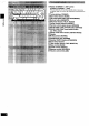
Before requesting service for this unit, check the chart below for a possible cause of the problem you are experiencing. Some simple checks or a minor adjustment on your part may eliminate the problem and restore proper operation.
• AMPLIFIER I_ated 40 SECTION minimum Hz-20 0.8% total kHz sine both harmonic • wave RMS channels power output distortion 80 W per channel (8 _) 1 Id-lz continuous power output both channels driven 0.05% total harmonic distortion 83 W per channel (8 Q) Total harmonic distortion Front Center Surround Low frequency damping factor Load Impedance Front Center Surround Frequency PHONO 0.8% (8 _) 0.