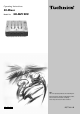
Operating Instructions DJ Mixer Model No. SH-MZ1200 The photograph shows the silver model. Note: “EB” on the packaging indicates the United Kingdom. Before connecting, operating or adjusting this product, please read these instructions completely. Please keep this manual for future reference.
Dear customer Thank you for purchasing this product. For optimum performance and safety, please read these instructions carefully. Table of contents Supplied accessories ................................................................... 2 Caution for AC Mains Lead ......................................................... 3 Safety precautions ....................................................................... 4 Main features ..............................................................................
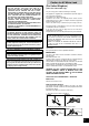
Caution for AC Mains Lead CAUTION! (For United Kingdom) • DO NOT INSTALL OR PLACE THIS UNIT IN A BOOKCASE, BUILT-IN CABINET OR IN ANOTHER CONFINED SPACE. ENSURE THE UNIT IS WELL VENTILATED. TO PREVENT RISK OF ELECTRIC SHOCK OR FIRE HAZARD DUE TO OVERHEATING, ENSURE THAT CURTAINS AND ANY OTHER MATERIALS DO NOT OBSTRUCT THE VENTILATION VENTS. •DO NOT OBSTRUCT THE UNIT’S VENTILATION OPENINGS WITH NEWSPAPERS, TABLECLOTHS, CURTAINS, AND SIMILAR ITEMS.
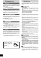
Safety precautions Main features Placement Set the unit up on an even surface away from direct sunlight, high temperatures, high humidity, and excessive vibration. These conditions can damage the cabinet and other components, thereby shortening the unit’s service life. Do not place heavy items on the unit. Voltage Do not use high voltage power sources. This can overload the unit and cause a fire. Do not use a DC power source.
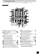
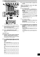
Component part names The unshaded numbers etc, correspond to the numbered illustrations. The shaded numbers etc, are reference pages. Control panel Input switch for adjusting left and right input individually (L/R SPLIT) ................................... Monitor control knob (MONITOR) .......................... , Input switch (CH1-CH4) ..........................................
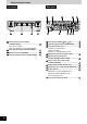
Component part names Front panel Rear panel Cross fader curve control switch Power button (POWER OFF ON) ................... (C.FADER CURVE) .................................................. Turntable earth terminal (PHONO EARTH) ........... Curve switch (CURVE) Cross fader operation switch (CROSS FADER) Input terminal (CH1-CH4) ....................................... Headphone terminal (PHONES) .............................
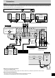
Connections Output side connections Connect the various equipment to the DJ mixer using stereo phono cables, connection cables and appropriate cables (Each sold separately). When connecting, make sure to turn all equipment power off. White (L) Red (R) Stereo phono cables Speakers (Not included) Speakers (Not included) Speakers (Not included) Amplifier (Not included) Monitor amplifier (Not included) Amplifier (Not included) Rear panel Connect when using an amplifier that has XLR terminals.
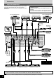
Connections Input side connections Connect the DJ mixer and various equipment with stereo phono cables, control cables and connection cables (Each sold separately). Connect the AC mains lead after completing all the other connections. Direct drive digital turntable 2 (Not included) Connection to the SH-MZ1200 rear panel PLAYER CONTROL terminal Only the separately sold direct drive digital turntable can be operated.
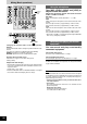
Mixing (Basic operations) 5 Use the channel fader to adjust the volume Select the CH2-CH4 source and adjust volume and sound (Same as instructions 3 - 5 indicated on the left) 6 L L/R SPLIT When using the cross fader Turn [ASSIGN A] and [ASSIGN B] to select the input channel to assign and •Select different input channels using the ASSIGN A and ASSIGN B switches. If the same input channel is selected by both switches, the volume will remain unchanged even when the cross fader is operated.
Mixing (Basic operations) Using the microphone OUTPUT LEVEL meter Turn [MIC LEVEL], [HIGH] and [LOW] to adjust volume and sound Adjusts the microphone volume and sound connected to MIC 1 and MIC 2 terminals. MIC LEVEL: Adjusts the microphone volume (Attenuation: – ∞ to 0 dB) HIGH: Adjusts the high tone microphone sound. Sound is flat at the center position.
Additional mixing operations Adjusting the monitor OUTPUT LEVEL meter You can check the sound on the headphones etc. during play and cue the channel you want to mix, and adjust the volume and check the mixing sound. Monitoring CH1 1 Press [CUE CH1] to turn on the monitor sound •The display lamp lights once the CUE button is pressed. •Monitor sound from the selected channel is output to PHONES (Headphones) and MONITOR OUT terminal. •Mixed sound can be output by pressing multiple CUE buttons.
Using play mode functions Output separation (dual output separation) By turning the SEPARATE OUT function ON, you can output audio through 2 separate channels, from MASTER OUT 1 (FRONT) and from MASTER OUT 2 (REAR). You can adjust the left and right output individually and use the cross fader for real time play. (e.g.
Fader start function You can start music play from the SL-DZ1200 direct drive digital turntable (not included) using the channel fader and cross fader by connecting the page 8) digital turntables to CH1 and CH4. (A control cable is necessary for this connection. Start using the cross fader When the digital turntable you want to control is connected to CH1 and the cross fader operation switch is set to NORMAL.
Block diagram CH1 DIGITAL IN CH2 CH3 CH4 DIGITAL IN EFFECT RETURN MIC1 MIC2 LINE CD/LINE CH1 LINE PHONO 1 LINE PHONO 2 PHONO 3 CD/LINE CH4 L R/MONO DAI Receiver PHONO EQ PHONO EQ PHONO EQ DAI Receiver MIC AMP HIGH/ MID/LOW CH1-CH4 HIGH TRIM CH1-CH4 L/R SPLIT ON/OFF L/R SPLIT ON/OFF CD/LINE LINE PHONO CH1-CH4 DAC DAC LOW RETURN MIC LEVEL MIC EQ CH1 CH4 CH3 CH2 V.C.A AMP V.C.A AMP V.C.A AMP V.C.
Maintenance To clean this unit, wipe with a soft, dry cloth. •Never use alcohol, paint thinner, or benzine to clean this unit. •Before using chemically treated cloth, read the instructions that came with the cloth carefully. Troubleshooting guide Before requesting service, make the below checks. If you are in doubt about some of the check points, or if the remedies indicated in the chart do not solve the problem, consult your dealer for instructions. Problem Check Action Page Reference No power.
Specifications Input sensitivity/input impedance PHONO (TRIM center) LINE (TRIM center) EFFECT RETURN MIC Rated output voltage/Output impedance MASTER 1, 2 (RCA) MASTER 1 (XLR) MONITOR REC OUT EFFECT SEND Headphone output Frequency response MASTER 1, 2 REC OUT EFFECT RETURN MIC Digital audio input Coaxial digital input Compatible sampling rate Digital audio output Coaxial digital output Sampling rate 2.5 mV/47 kΩ 250 mV/10 kΩ 250 mV/47 kΩ 0.