
Operating Instructions


7
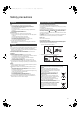
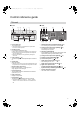
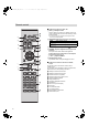
Control reference guide
∫ Front
1 Power switch lever
Turn on/off this unit.
≥ The remote control do not operate when the power switch
lever is in the lowered position.
2 Headphones jack
For connecting a headphone plug.
≥ When a plug is connected, the speakers do not output sound.
≥ Excessive sound pressure from earphones and headphones
can cause hearing loss.
≥ Listening at full volume for long periods may damage the
user’s ears.
3 LAPC indicator (> 13)
The indicator lights up when amplifier output correction is
on.
4 Volume knob
Adjust the volume.
≥ When this unit is muted, if you turn the knob anticlockwise until
it stops and then turn it clockwise, the muting will be cancelled.
5 Remote control signal sensor
Distance: Within approx. 7 m directly in front
Angle: Approx. 30o left and right
6 Input selector knob
Turn this knob clockwise or anticlockwise to switch the
input source. (> 13)
7 Peak power meter
Display the output level.
8 Input indicator (> 13)
The indicator for the selected input source lights up.
≥ The indicator blinks if you select “PC”, “COAX1”, “COAX2”,
“COAX3” or “OPT” when the device is not connected to this
unit.
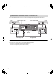
∫ Rear
9 PHONO EARTH terminal [PHONO EARTH] (> 11)
For connecting the ground wire of a record player.
: Analogue audio input terminal [PHONO] (> 11)
For connecting a record player.
≥ MM cartridges are supported.
; Attenuator [ATTENUATOR]
If audio distortion occurs when using the analogue audio
input terminal [LINE IN], set this switch to [ON].
< Analogue audio input terminal [LINE IN] (> 11)
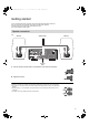
= Speaker terminals [SPEAKERS] (> 9)
> AC IN terminal [AC IN T] (> 12)
? Digital audio input terminal [PC] (> 15)
For connecting to a PC, etc.
@ Digital audio input terminal [OPT IN] (> 11)
A Digital audio input terminals
[COAX1 IN]/[COAX2 IN]/[COAX3 IN] (> 10, 11)
B System terminals [CONTROL1]/[CONTROL2] (> 10)
C Product identification marking
The model number is indicated.
This unit
SU-C700-SQT0487_EBGN_mst.book 7 ページ 2015年6月15日 月曜日 午前9時20分