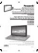
Operating Instructions Progressive Wide Plasma Display Manual de instrucciones S9 TH-42P Pantalla panorámica de plasma progresiva Model No. Número de modelo. TH-42PS9UK TH-42PS9XK High Definition Plasma Display Pantalla de Plasma de Alta Definición Model No. Número de modelo. TH-37PH9UK TH-42PH9UK TH-42PH9XK TH-50PH9UK TH-50PH9XK TH-42PS9 The illustration shown is an image. Before connecting, operating or adjusting this product, please read these instructions completely.
CAUTION RISK OF ELECTRIC SHOCK DO NOT OPEN WARNING: To reduce the risk of electric shock, do not remove cover or back. No user-serviceable parts inside. Refer servicing to qualified service personnel. The lightning flash with arrow-head within a triangle is intended to tell the user that parts inside the product are a risk of electric shock to persons.
Important Safety Instructions 1) Read these instructions. 2) Keep these instructions. 3) Heed all warnings. 4) Follow all instructions. 5) Do not use this apparatus near water. 6) Clean only with dry cloth. 7) Do not block any ventilation openings. Install in accordance with the manufacturer’s instructions. 8) Do not install near any heat sources such as radiators, heat registers, stoves, or other apparatus (including amplifiers) that produce heat.
Dear Panasonic Customer Welcome to the Panasonic family of customers. We hope that you will have many years of enjoyment from your new Plasma Display. To obtain maximum benefit from your set, please read these Instructions before making any adjustments, and retain them for future reference. Retain your purchase receipt as well, and record the model number and serial number of your set in the space provided on the rear cover of these instructions. Table of Contents Important Safety Instructions.............
FCC STATEMENT This equipment has been tested and found to comply with the limits for a Class B digital device, pursuant to Part 15 of the FCC Rules. These limits are designed to provide reasonable protection against harmful interference in a residential installation. This equipment generates, uses and can radiate radio frequency energy and, if not installed and used in accordance with the instructions, may cause harmful interference to radio communications.
Safety Precautions CAUTION This Plasma Display is for use only with the following optional accessories. Use with any other type of optional accessories may cause instability which could result in the possibility of injury. (All of the following accessories are manufactured by Matsushita Electric Industrial Co., Ltd.) • Speakers .....................................................................
Safety Precautions / Maintenance WARNING Setup Do not place the Plasma Display on sloped or unstable surfaces. • The Plasma Display may fall off or tip over. Do not place any objects on top of the Plasma Display. • If water spills onto the Plasma Display or foreign objects get inside it, a short-circuit may occur which could result in fire or electric shock. If any foreign objects get inside the Plasma Display, please consult an Authorized Service Center. Do not cover the ventilation holes.
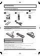
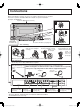
Accessories Accessories Supplied Check that you have the Accessories and items shown Operating Instruction book Remote Control Transmitter EUR7636070R Fixing bands × 2 AC cord Batteries for the Remote Control Transmitter (2 × AA Size) Remote Control Batteries Requires two AA batteries. 1. Pull and hold the hook, then open the battery cover. 2. I n s e r t b a t t e r i e s - n o t e c o r r e c t polarity ( + and -). 3. Replace the cover.
Connections When connecting the speakers, be sure to use only the optional accessory speakers. Refer to the speaker’s Installation Manual for details on speaker installation. (Example: TH-42PS9UK) Speakers (Optional accessories) 1 2 SPEAKERS Terminals (L) SPEAKERS Terminals (R) 1 2 AC cord connection (see page 13) – AC cord fixing 1. Open the clamper. 3. Slide up the clamper and fix 4. Insert the point of the fixed clamper into the the AC cord plug securely.
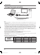
Connections PC Input Terminals connection COMPUTER AUDIO PC IN TH-42PS9 Conversion adapter (if necessary) RGB Mini D-sub 15p PC cable Audio Stereo plug Connect a cable which matches the audio output terminal on the computer. Notes: • Due to space limitations, occasionally you may have trouble connecting Mini D-sub 15P cable with ferrite core to PC input Terminal.
Connections SERIAL Terminals connection The SERIAL terminal is used when the Plasma Display is controlled by a computer. COMPUTER 6 1 7 2 8 3 9 4 5 SERIAL RS-232C Straight cable Pin layout for RS-232C D-sub 9p Notes: • Use the RS-232C cable to connect the computer to the Plasma Display. • The computer shown is for example purposes only. • Additional equipment and cables shown are not supplied with this set.
Connections AV & COMPONENT / RGB connection COMPONENT VIDEO OUT RR Example of input signal source Y, PB, PR, OUT DVD PB RCA-BNC adapter plug Y Digital TV-SET-TOP-BOX (DTV-STB) L AUDIO OUT R R AUDIO L B SLOT1 S VIDEO R AUDIO AV IN L VIDEO A R AUDIO L PR/CR/R PB/CB/B Y/G AUDIO COMPONENT/RGB IN SLOT2 PC SLOT3 IN SERIAL Example of input signal source S VIDEO VCR CAMCORDER VCR R L S VIDEO R L OUT AUDIO AUDIO OUT OUT VIDEO OUT Notes: • Change the “COMPONENT/RGB-IN SELECT” setting
Power ON / OFF Connecting the AC cord plug to the Plasma Display. Fix the AC cord plug securely to the Plasma Display with the clamper. (see page 9) Connecting the plug to the Wall Outlet Press the Power switch on the Plasma Display to turn the set on: Power-On. Power Indicator: Green TH-42PWD8 INPUT MENU From the second time on, language selection can be done from the setup menu.
Basic Controls Remote control sensor Volume Adjustment Volume Up “+” Down “–” When the menu screen is displayed: “+” : press to move the cursor up “–” : press to move the cursor down (see page 16) TH-42PS9 INPUT MENU Main Power On / Off Switch Power Indicator The Power Indicator will light. • Power-OFF .... Indicator not illuminated (The unit will still consume some power as long as the power cord is still inserted into the wall outlet.) • Standby ......... Red • Power-ON ...... Green • DPMS ..........
Basic Controls Standby (ON / OFF) button The Plasma Display must first be plugged into the wall outlet and turned on at the power switch (see page 13). Press ON to turn the Plasma Display On, from Standby mode. Press OFF to turn the Plasma Display Off to Standby mode. POSITION buttons ACTION button Press to make selections. R button (see page 17) Press the R button to return to previous menu screen. Status button Press the “Status” button to display the current system status.
On-Screen Menu Displays The MENU button on the unit can also be pressed. To PICTURE adjust menu (see page 23) PICTURE 1 Press to select . 1/2 NORMALIZE NORMAL INPUT STANDARD 25 0 0 0 3 PICTURE MENU PICTURE BRIGHTNESS COLOR TINT SHARPNESS PICTURE MENU -/ VOL +/ ENTER/ Each time the MENU button is pressed, the menu screen will switch. Normal Viewing PICTURE SETUP SOUND POS.
On-Screen Menu Displays 2 Press to access each adjust screen. [ from the unit ] INPUT MENU -/ VOL +/ ENTER/ Press to return to next menu screen.
Initial selections Selecting the input signal Select the input signals to be connected by installing the optional Terminal Boards. Press to select the input signal to be played back from the equipment which has been connected to the Plasma Display. Input signals will change as follows: • TH-37PH9UK INPUT1 INPUT2 PC IN • TH-42PS9UK, ,TH-42PS9XK, TH-42PH9UK, TH-42PH9XK, TH-50PH9UK, TH-50PH9XK INPUT1 INPUT2 INPUT3 PC IN Notes: • Selecting is also possible by pressing the INPUT button on the unit.
ASPECT Controls The Plasma Display will allow you to enjoy viewing the picture at its maximum size, including wide screen cinema format picture. Press repeatedly to move through the aspect options: NORMAL ZOOM Panasonic AUTO [from the unit] INPUT MENU -/ VOL +/ FULL JUST The aspect mode changes each time the ENTER button is pressed. ENTER/ [During MULTI PIP Operations] • Picture and Picture, Picture in Picture : • Others NORMAL FULL : Aspect switching is not possible.
Adjusting POS. /SIZE 1 Press to display the POS. /SIZE menu. 2 Press to select H-POS / H-SIZE / V-POS / V-SIZE / CLOCK PHASE. 3 Press to adjust POS. /SIZE. During “VIDEO (S VIDEO)”, “COMPONENT” and “Digital” input signal. 4 POS. /SIZE Press to exit from adjust mode.
MULTI PIP Press repeatedly. Each time pressing this button main picture and sub picture will be displayed as follows below. [Picture and Picture] Main picture Main picture Sub picture MULTI PIP Normal Viewing [Picture out Picture] A B B Main picture Sub picture MULTI PIP SWAP Press to swap main picture and sub picture.
Advanced PIP 1 Press to display the Setup menu. 2 Press to select “OSD Language”. 3 Press and hold until the Options menu is displayed. Press to select Advanced PIP. 4 1/3 Options Off-timer function Onscreen display Initial INPUT Initial VOL level Maximum VOL level INPUT lock Studio W/B Advanced PIP Display size Press to adjust the menu. Off : Sets normal two screen display mode (see page 21). On : Sets Advanced PIP mode. 5 Press to confirm. 6 One screen Press to exit from Options menu.
PICTURE Adjustments 1 2 Press to display the PICTURE menu. Select to adjust each item. Press to select the menu to adjust. Select the desired level by looking at the picture behind the menu. PICTURE 1/2 NORMALIZE NORMAL Press the left STANDARD 25 0 0 0 3 PICTURE MENU PICTURE BRIGHTNESS COLOR TINT SHARPNESS PICTURE or right button to switch between modes. STANDARD CINEMA DYNAMIC STANDARD For viewing in standard (evening lighting) environments.
PICTURE Adjustments Item PICTURE BRIGHTNESS COLOR TINT SHARPNESS Effect Less More Darker Brighter Less More Reddish Greenish Less More Adjustments Adjusts the proper picture contrast. Adjusts for easier viewing of dark pictures such as night scenes and black hair. Adjusts color saturation. Adjusts for natural flesh tones. Adjusts picture sharpness. Notes: • “COLOR” and “TINT” settings cannot be adjusted for “RGB/PC” and “Digital” input signal.
SOUND Adjustment 1 Press to display the SOUND menu. 2 Select to adjust each item. Press to select the menu to adjust. Select the desired level by listening to the sound. BASS Adjusts low pitch sounds SOUND STANDARD Emits the original sound.
Digital Zoom This displays an enlargement of the designated part of the displayed image. 1 Display the “Operation Guide”. EXIT Press to access Digital Zoom. The “Operation Guide” will be displayed. 1 During Digital Zoom, only the following buttons can be operated. [Remote control] [Unit] INPUT MENU -/ VOL +/ ENTER/ VOL button VOL button MUTE button SURROUND button OFF TIMER button 2 Select the area of the image to be enlarged. Press on the enlargement location to select.
PRESENT TIME SETUP / SET UP TIMER The timer can switch the Plasma Display ON or OFF. Before attempting Timer Set, confirm the PRESENT TIME OF DAY and adjust if necessary. Then set POWER ON TIME / POWER OFF TIME. 1 Press to display the SET UP menu. 2 Press to select SET UP TIMER or PRESENT TIME SETUP. Press to display the SET UP TIMER screen or PRESENT TIME SETUP screen.
PRESENT TIME SETUP / SET UP TIMER SET UP TIMER Display the SET UP TIMER SCREEN. 1 Press to select POWER ON TIME / POWER OFF TIME. Press to set up POWER ON TIME / POWER OFF TIME. button: Forward button: Back SET UP TIMER PRESENT TIME OF DAY 99:99 POWER ON FUNCTION POWER ON TIME POWER OFF FUNCTION POWER OFF TIME OFF 0:00 OFF 0:00 Notes: • Pressing “ ” or “ ” button once changes POWER ON TIME / POWER OFF TIME 1minute.
SCREENSAVER (For preventing after-images) Do not display a still picture, especially in NORMAL mode, for any length of time. If the display must remain on, a SCREENSAVER should be used. SET UP 1 Press to display the SET UP menu. Press to select the SCREENSAVER. 2 2/2 SCREENSAVER MULTI DISPLAY SETUP SET UP TIMER PRESENT TIME SETUP Press to select the SCREENSAVER screen. 3 SCREENSAVER NEGATIVE / SCROLL selection Press to select the FUNCTION. Press to select the desired function.
SCREENSAVER (For preventing after-images) Setup of SCREENSAVER Time After selecting TIME OF DAY or INTERVAL, the relevant Time Setup will become available for selection and the Operating Time may be set. (Time cannot be set when “MODE” is “ON” or “OFF”.
SCREENSAVER (For preventing after-images ) SIDE BAR ADJUST Do not display a picture in NORMAL mode for an extended period, as this can cause an after-image to remain on the side bars on either side of the display field. To reduce the risk of such an after-image, change the brightness of the side bars. side bars NORMAL mode after-images This function may be applicable to the non-picture area. Non picture area A Picture out Picture B Picture and Picture Display the SCREENSAVER screen.
Reduces power consumption • POWER SAVE: • STANDBY SAVE: • POWER MANAGEMENT: • AUTO POWER OFF: 1 When this function is turned ON, luminous level of the Plasma Display is suppressed, so power consumption is reduced. When this function is turned ON, power consumption of the microcomputer is reduced during power supply standby (see page 13-15), so standby power of the set is reduced. The unit power supply is turned ON or OFF depending on whether or not there is a signal during PC input mode.
SET UP for MULTI DISPLAY (For TH-42PS9UK, TH-42PS9XK) By lining up Plasma Displays in groups of 4, 9 or 16 as illustrated below, an enlarged picture may be displayed across all screens. For this mode of operation, each plasma display has to be set up with a Display number to determine its location. group of 4 (2 × 2 (F)) group of 9 (3 × 3 (F)) group of 16 (4 × 4 (F)) Two options are selectable for MULTI DISPLAY (See page 37). How to setup MULTI DISPLAY 1 Press to display the SET UP menu.
SET UP for MULTI DISPLAY How to set the Display location number for each Plasma Display 4 Press to select ARRANGEMENT (2nd step). Press to select “2 × 2”, “2 × 2F”, “3 × 3”, “3 × 3F”, “4 × 4”, “4 × 4F”. 5 MULTI DISPLAY SETUP MULTI DISPLAY SETUP ARRANGEMENT LOCATION OFF 2×2 A1 Press to select LOCATION. MULTI DISPLAY SETUP Press to select the required arrangement number.
SET UP for MULTI DISPLAY (For TH-37PH9UK, TH-42PH9UK, TH-42PH9XK, TH-50PH9UK, TH-50PH9XK) By lining up Plasma Displays in groups, for example, as illustrated below, an enlarged picture may be displayed across all screens. For this mode of operation, each plasma display has to be set up with a Display number to determine its location. (Example) group of 4 (2 × 2) group of 9 (3 × 3) group of 16 (4 × 4) (see page 37 for more displays lineups.) How to setup MULTI DISPLAY 1 Press to display the SET UP menu.
SET UP for MULTI DISPLAY How to set the Display location number for each Plasma Display 4 Press to select HORIZONTAL SCALE. MULTI DISPLAY SETUP MULTI DISPLAY SETUP HORIZONTAL SCALE VERTICAL SCALE SEAM HIDES VIDEO LOCATION Press to select “× 1”, “× 2”, “× 3”, “× 4”. 5 Press to select VERTICAL SCALE. MULTI DISPLAY SETUP MULTI DISPLAY SETUP HORIZONTAL SCALE VERTICAL SCALE SEAM HIDES VIDEO LOCATION Press to select “× 1”, “× 2”, “× 3”, “× 4”. 6 Press to select SEAM HIDES VIDEO.
SET UP for MULTI DISPLAY F (SEAM HIDES VIDEO) Setting Model No. To hide joints between TVs. To show joints between TVs. Suitable for moving image display. Suitable for still image display. Step 4, Page 34 (2 × 2, 3 × 3, 4 × 4) (2 × 2F, 3 × 3F, 4 × 4F) Step 6, Page 36 ON OFF Reference TH-42PS9UK TH-42PS9XK TH-37/42/50PH9UK TH-42/50PH9XK ID Remote Control Function You can set the remote control ID when you want to use this remote control on one of several different TVs.
SET UP for Input Signals COMPONENT / RGB IN SELECT Select to match the signals from the source connected to the COMPONENT / RGB input terminals. Y, PB, PR signals “COMPONENT” R, G, B, HD, VD signals “RGB” 1 Press to display the SET UP menu. 2 Press to select the “COMPONENT / RGB-IN SELECT”. Press to select the desired mode. COMPONENT RGB SET UP 3 Press to exit from adjust mode.
SET UP for Input Signals COLOR SYSTEM / Panasonic AUTO Select SIGNAL from the “SET UP” menu during VIDEO (S VIDEO) input signal mode.(“SIGNAL [VIDEO]” menu is displayed.) SET UP 1/2 SIGNAL COMPONENT/RGB-IN SELECT RGB INPUT LABEL PC POWER SAVE OFF STANDBY SAVE OFF POWER MANAGEMENT OFF AUTO POWER OFF OFF OSD LANGUAGE ENGLISH (US) Press to select the “COLOR SYSTEM” or “Panasonic AUTO”. Press to select each function.
SET UP for Input Signals SYNC Select SIGNAL from the “SET UP” menu during RGB input signal. 1 Press to adjust. SET UP 1/2 SIGNAL COMPONENT/RGB-IN SELECT RGB INPUT LABEL PC POWER SAVE OFF STANDBY SAVE OFF POWER MANAGEMENT OFF AUTO POWER OFF OFF OSD LANGUAGE ENGLISH (US) Press ACTION ( ) button 2 [ RGB ] SIGNAL Press to exit from adjust mode. SYNC 3 : 2 PULLDOWN VIDEO NR AUTO OFF OFF H-FREQ. 33.8 kHz V-FREQ. 60.
Options Adjustments 1 Press to display the Setup menu. 2 Press to select “OSD Language”. 3 Press and hold until the Options menu is displayed. 4 Press to select your preferred menu. 5 Press to adjust the menu. Options Off-timer function Onscreen display Initial INPUT Initial VOL level Maximum VOL level INPUT lock Studio W/B Advanced PIP Display size Press to confirm. 6 Press to exit from Options menu.
Options Adjustments Options Off-timer function Onscreen display Initial INPUT Initial VOL level Maximum VOL level INPUT lock Studio W/B Advanced PIP Display size Item Effect Off On Off On button to adjust the volume when TV is turned on. Off On Off: Sets normal volume. On: Sets your preferred volume. Notes: • When “Maximum VOL level” is “On”, the volume can only be adjusted between 0 and your maximum range.
Options Adjustments 2/3 Options Button lock Remocon User level ID select Remote ID Serial ID Item Effect Off Off 0 Off Off Adjustments Off MENU&ENTER On Off: All the buttons at the bottom of the main unit can be used. MENU & ENTER: Button lock and Locks MENU On: buttons on bottom face of main unit. ENTER/ Locks all the button on bottom face of main unit. Off User1 User2 User3 Off: You can use all of the buttons on the remote control.
Shipping condition This function allows you to reset the unit to the factory setting. 1 Press to display the SET UP menu. 2 Press to select “OSD LANGUAGE”. 3 Press and hold till the SHIPPING menu is displayed. 4 Press to select “YES”. 1/2 SET UP SIGNAL COMPONENT/RGB-IN SELECT RGB INPUT LABEL PC POWER SAVE OFF STANDBY SAVE OFF POWER MANAGEMENT OFF AUTO POWER OFF OFF OSD LANGUAGE ENGLISH (US) SHIPPING YES Press to confirm. [from the unit] 1 Press the MENU button till the Setup menu is displayed.
Troubleshooting Before you call for service, determine the symptoms and make a few simple checks as shown below. Symptoms Picture Checks Sound Interference Noisy Sound Electrical Appliances Cars / Motorcycles Fluorescent light Normal Picture No Sound Volume (Check whether the mute function has been activated on the remote control.
VIDEO/COMPONENT/RGB/PC input signals VIDEO input Signal name 1 2 3 4 5 NTSC PAL PAL60 SECAM Modified NTSC Horizontal frequency(kHz) 15.73 15.63 15.73 15.63 15.73 Vertical frequency(Hz) 59.94 50.00 59.94 50.00 59.94 Applicable input signals for Component / Mini D-sub 15P (Component) / RGB / Mini D-sub 15P (RGB) (∗ Mark) Component / RGB / Horizontal Vertical Signal name Mini D-sub 15P Mini D-sub 15P frequency (kHz) frequency (Hz) (Component) (RGB) 1 525 (480) / 60i 15.73 59.94 ∗ ∗ 2 525 (480) / 60p 31.
Specifications TH-42PS9UK, TH-42PS9XK Power Source 120 V AC, 50 / 60 Hz (TH-42PS9UK) 110 - 127 V AC, 50 / 60 Hz (TH-42PS9XK) Power Consumption Power on Stand-by condition Power off condition Plasma Display panel Contrast Ratio Screen size (No.
Specifications TH-37PH9UK TH-42PH9UK, TH-42PH9XK 120 V AC, 50 / 60 Hz (TH-37PH9UK, TH-42PH9UK) 110 - 127 V AC, 50 / 60 Hz (TH-42PH9XK) Power Source Power Consumption Power on Stand-by condition Power off condition Plasma Display panel 300W Save OFF 0.6 W, Save ON 0.4 W 0.1 W Drive method : AC type 37-inch, 16:9 aspect ratio Contrast Ratio Screen size (No.
Specifications TH-50PH9UK, TH-50PH9XK 120 V AC, 50 / 60 Hz (TH-50PH9UK) 110 - 127 V AC, 50 / 60 Hz (TH-50PH9XK) Power Source Power Consumption Power on Stand-by condition Power off condition Plasma Display panel 460W Save OFF 0.5 W, Save ON 0.3 W 0.1 W Drive method : AC type 50-inch, 16:9 aspect ratio Contrast Ratio Screen size (No.
(for U.S.A.) Panasonic Broadcast & Television Systems Company, Unit of Panasonic Corporation of North America One Panasonic Way 2A-4 Secaucus, NJ 07094 Panasonic Puerto Rico, Inc. Ave. 65de Infanteria, Km.9.5 San Gabriel Industrial Park Carolina, Puerto Rico 00985 PANASONIC PLASMA SCREEN Limited Warranty Panasonic Broadcast & Television Systems Company or Panasonic Puerto Rico, Inc.
(for Canada) Panasonic Canada Inc. Broadcast & Television Systems Division 5770 Ambler Drive, Mississauga, Ontario L4W 2T3 LIMITED WARRANTY STATEMENT Panasonic Canada Inc. (also known as PCI) warrants this product to be free of defects in material and workmanship under normal use during the applicable warranty coverage period described below. PCI agrees to repair, or at its option, exchange, any part that becomes defective. However, the product must be purchased and serviced in Canada.
Customer’s Record The model number and serial number of this product can be found on its back cover. You should note this serial number in the space provided below and retain this book, plus your purchase receipt, as a permanent record of your purchase to aid in identification in the event of theft or loss, and for Warranty Service purposes. Model Number Serial Number © 2006 Matsushita Electric Industrial Co., Ltd. All Rights Reserved.