
Operating Instructions

FAQs, etc.
•
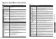
Frequently Asked Questions
•
Technical Information
36
37
Technical Information
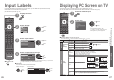
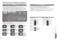
Input signal that can be displayed
Note
•
Signals other than above may not be displayed properly.
•
The above signals are reformatted for optimal viewing on your display.
•
Applicable input signal for PC is basically compatible to VESA standard timing.
•
PC signal is magnifi ed or compressed for display, so that it may not be possible to show fi ne detail
with suffi cient clarity.
Signal name COMPONENT HDMI
525 (480) / 60i
∗∗
525 (480) / 60p
∗∗
625 (576) / 50i
∗∗
625 (576) / 50p
∗∗
750 (720) / 60p
∗∗
750 (720) / 50p
∗∗
1,125 (1,080) / 60i
∗∗
1,125 (1,080) / 50i
∗∗
1,125 (1,080) / 60p
∗
1,125 (1,080) / 50p
∗
Signal name Horizontal frequency (kHz) Vertical frequency (Hz)
640 × 400 @70 Hz 31.47 70.07
640 × 480 @60 Hz 31.47 59.94
640 × 480 @75 Hz 37.50 75.00
800 × 600 @60 Hz 37.88 60.32
800 × 600 @75 Hz 46.88 75.00
800 × 600 @85 Hz 53.67 85.06
852 × 480 @60 Hz 31.44 59.89
1,024 × 768 @60 Hz 48.36 60.00
1,024 × 768 @70 Hz 56.48 70.07
1,024 × 768 @75 Hz 60.02 75.03
1,024 × 768 @85 Hz 68.68 85.00
1,280 × 1,024 @60 Hz 63.98 60.02
1,366 × 768 @60 Hz 48.39 60.04
Macintosh13” (640 × 480) 35.00 66.67
Macintosh16” (832 × 624) 49.73 74.55
Macintosh21” (1,152 × 870) 68.68 75.06
∗
Mark: Applicable input signal
COMPONENT (Y, PB, PR), HDMI
PC (D-sub 15P)
Pin No.
Signal Name
Pin No.
Signal Name
Pin No.
Signal Name
R GND (Ground) NC (not connected)
G GND (Ground) NC (not connected)
B GND (Ground) HD
NC (not connected) NC (not connected) VD
GND (Ground) GND (Ground) NC (not connected)
1
678
3
9
45
10
15 14 13 12 11
2
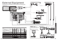
PC connection
A PC may be connected to this TV so that the PC screen is displayed and sound is heard from the TV.
•
PC signals that can be inputted: Horizontal scanning frequency 31 to 69 kHz; vertical scanning frequency
59 to 86 Hz (more than 1,024 signal lines could result in incorrect display of the image).
•
A PC adapter is not necessary for the DOS/V-compliant D-sub 15-pin connector.
Note
•
Some PC models cannot be connected to this TV.
•
When using PC, set the colour display quality of PC to the highest position.
•
For details of the applicable PC signals, see below.
•
Max. display resolution
•
D-sub 15-pin connector signal
FAQs
Before requesting service or assistance, please follow these simple guides to resolve the problem.
If problem still persists, please contact your local Panasonic dealer for assistance.
White spots or shadow
images (noise)
•
Check the position, direction, and
connection of the aerial.
Neither image nor
sound is produced
•
Is the TV in “AV mode”?
•
Is the mains lead plugged into the socket
outlet?
•
Is the TV turned On?
•
Check Picture Menu (p. 20) and volume.
•
Check all required SCART cables and
connections are fi rmly in place.
Auto aspect
•
Auto aspect is designed to provide you
with the best aspect ratio to use to fi ll your
screen. For user control please see p. 34.
S-Video / black and
white picture
•
Using AV button please confi rm your
selection is S-Video I.e. AV2/AV2S
(p. 14).
On Screen messages
- I.e. EC/AV1
•
You can simply clear these by pressing
the button .
Press again to redisplay.
Direct TV record / Q-Link
functions not recording
•
Please confi rm SCART cable and connection. Also
please set “AV1 / AV2 out” in the Setup Menu (p. 21).
Permanently lit spots on screen
•
Due to production process involved in this technology
this may result in some pixels which are permanently lit
or unlit. This is not a malfunction.
Contrast is reduced
•
Contrast is lowered when the following conditions without
any user operation for a few minutes:
● no signal in AV mode
● selected locked channel
● selected invalid channel
● selected radio channel
● displayed menu
TH-37PV70F TH-42PV70F TH-50PV70F
4:3 768 × 720 pixels 768 × 768 pixels 1,024 × 768 pixels
16:9 1,024 × 720 pixels 1,024 × 768 pixels 1,366 × 768 pixels
Aspect
Model No.