
Operating instructions

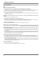

10
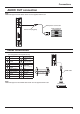
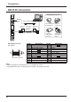
DVI-D IN connection
Pin No.
Signal Name
Pin No.
Signal Name
1
T.M.D.S. data 2-
13
2
T.M.D.S. data 2+
14
+5 V DC
3
T.M.D.S. data 2 shield
15
Ground
4
16
Hot plug detect
5
17
T.M.D.S. data 0-
6
DDC clock
18
T.M.D.S. data 0+
7
DDC data
19
T.M.D.S. data 0 shield
8
20
9
T.M.D.S. data 1-
21
10
T.M.D.S. data 1+
22
T.M.D.S. clock shield
11
T.M.D.S. data 1 shield
23
T.M.D.S. clock+
12 24
T.M.D.S. clock-
Notes:
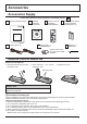
• Additional equipment and cables shown are not supplied with this set.
• Image deterioration may occur depending on the length or the quality of the cable.
DVI-D Input Connector
Pin Layouts
Connection port view
9
8
1
17
24
16
Connections
Stereo mini plug (M3)
Shared
with PC
IN.
PC with DVI-D
video out
Less than
5 cm
Ferrite core
(supplied)
DVI-video cable (Within 5 m)
Less than
5 cm
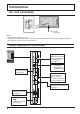
Pull back the tabs
(in two places)
Route the
cable through
and close
Fix the Ferrite
core with the
cable tie
Open the
Ferrite core
Installing the Ferrite core
1. 2.
3. 4.