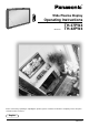
® Wide Plasma Display PLASMA DISPLAY + — VOL INPUT POWE R / BY R - STAND ON G POWER Operating Instructions TH-37PW4 Model No. TH-42PW4 Before connecting, operating or adjusting this product, please read these instructions completely. Please keep this manual for future reference.
Dear Panasonic Customer Welcome to the Panasonic family of customers. We hope that you will have many years of enjoyment from your new Plasma Display. To obtain maximum benefit from your set, please read these Instructions before making any adjustments, and retain them for future reference. Retain your purchase receipt also, and note down the model number and serial number of your set in the space provided on the rear cover of these instructions. Visit our Panasonic Web Site http://www.panasonic.co.
Table of Contents Important Safety Notice .............................................. 4 Safety Precautions ...................................................... 5 Accessories ................................................................. 7 Accessories Supply .................................................... 7 Optional Accessories ................................................. 7 Remote Control Batteries ........................................... 8 Connections ...................................
Important Safety Notice WARNING: To prevent damage which may result in fire or shock hazard, do not expose this appliance to rain or moisture. Do not place containers with water (flower vase, cups, cosmetics, etc.) above the set. (including on shelves above, etc.) WARNING: 1) To prevent electric shock, do not remove cover. No user serviceable parts inside. Refer servicing to qualified service personnel. 2) Do not remove the earthing pin on the power plug.
Safety Precautions WARNING Setup This Plasma Display is for use only with the following optional accessories. Use with any other type of optional accessories may cause instability which could result in the possibility of injury. • • • • • • • (All of the following accessories are manufactured by Matsushita Electric Industrial Co., Ltd.) Speakers ......................................... TY-SP37P4W-S(TH-37PW4), TY-SP42PM3W(TH-42PW4) Pedestal ..........................................
Safety Precautions If problems occur during use If a problem occurs (such as no picture or no sound), or if smoke or an abnormal odour starts to come out from the Plasma Display, immediately unplug the power cord plug from the wall outlet. If you continue to use the Plasma Display in this condition, fire or electric shock could result. After checking that the smoke has stopped, contact your local Panasonic dealer so that the necessary repairs can be made.
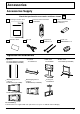
Accessories Accessories Supply Check that you have the accessories and items shown Remote Control Transmitter EUR646525 Operating Instruction book Batteries for the Remote Control Transmitter (2 × R6 Size) INPUT SURROUND VOL N R PICTURE SOUND SET UP PICTURE POS.
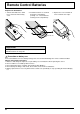
Remote Control Batteries Requires two R6 batteries. 1. Turn the transmitter face down. Press and slide off the battery cover. 2. Install the batteries as shown in the battery compartment. (Polarity + or – must match the markings in the compartment). 3. Replace the cover and slide in reverse until the lock snaps. Two "R6" size Helpful Hint: For frequent remote control users, replace old batteries with Alkaline batteries for longer life.
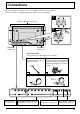
Connections When connecting the speakers, be sure to use only the optional accessory speakers. Refer to the speaker’s Installation Manual for details on speaker installation. 1 Speakers (Optional accessories) 2 1 2 SPEAKERS Terminals (R) SPEAKERS Terminals (L) – Cable fixing bands Secure any excess cables with bands as required. Pass the attached cable fixing band through the clip as shown in the figure.
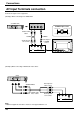
Connections AV Input Terminals connection Connect the signal source equipment. (Example) When connecting an S VIDEO VCR (S VIDEO VCR) R Audio OUT L Video OUT S Video OUT S VIDEO 4 pin socket 2×RCA audio cables AUDIO Luminance earth Chrominance earth Luminance in Chrominance in S VIDEO Video input to S VIDEO socket Audio input to L/R sockets R L AUDIO VIDEO S VIDEO AV IN (Example) When connecting 3×RCA audio video cables.
Connections (Example) When connecting 21 pin scart cables. (VCR) AV2 Video input to BNC socket BNC-RCA adaptor plug Audio input to L/R sockets (DVD / Satellite Receiver) R L AUDIO VIDEO S VIDEO AV IN AV1/TV Video input to RCA socket Audio input to L/R sockets Notes: (1) Additional equipment, cables and an adapter plug shown are not supplied with this set. (2) 21 pin connectors and 21 pin scart plugs are connectors used in Europe.
Connections RGB signal (R, G, B, HD, VD) connection BNC-RCA adaptor plug RGB input to R, G, B, HD, VD sockets Example of input signal source HDTV-compatible VCR 5×BNC RGB cables RGB camera R L AUDIO VD HD PR/CR/R PB/CB/B COMPONENT/RGB IN AUDIO 2×RCA audio cables Audio input to L/R sockets Computer VD HD R B G Notes: (1) Change the “Component/RGB-in” setting in the “Setup” menu to “RGB”. (see page 30, 32) (2) Additional equipment, cables and adapter plugs shown are not supplied with this set.
Connections How to connect the PC Input Terminals COMPUTER AUDIO PC IN POWER / R - STANDBY INPUT – VOL + G POWER ON Conversion adapter (if necessary) D-sub 15p RGB PC cable Ferrite core (supplied) Less than 7" 7/8 (20 cm) Audio 1/8" (3mm) stereo plug Connect a cable which matches the audio output terminal on the computer.
Connections How to connect the SERIAL Terminals The SERIAL terminal is used when the Plasma Display is controlled by a computer. COMPUTER SERIAL Ferrite core (supplied) RS-232C straight cable 6 1 2 8 3 9 4 5 Pin layout for RS-232C Less than 7" 7/8 (20 cm) D-sub 9p 7 Notes: (1) Use the RS-232C cable to connect the computer to the Plasma Display. (2) The computers shown is for example purposes only. (3) Additional equipment and cables shown are not supplied with this set.
Basic Controls INPUT R - STANDBY G POWER ON – VOL + TH-42PW4 Main Power On/Off Switch Power Indicator The Power Indicator will light. Power-OFF ..... Indicator not illuminated (The unit will still consume some power as long as the power cord is still inserted into the wall outlet.) Stand-by .... Red Power-ON ...... Green • • • INPUT button (AV (S Video)/Component, RGB/PC Mode Selection) Push the “INPUT” button to select AV(S Video)/Component or RGB/PC input signal modes sequentially.
Power On/Off and input signal selection AC cord connection Connecting the AC cord plug to the Plasma Display. Power On/Off Connecting the plug to the Wall Outlet Note: Main plug types vary between countries. The power plug shown at left may, therefore, not be the type fitted to your set.
Power On/Off and input signal selection Select the input signal INPUT Press the INPUT button to select the input AV signal desired from equipment such as a VCR which has been connected to the Plasma Display. Input signals will change as follows: R - STANDBY — INPUT VOL + For Component Input (see page 30) G POWER ON AV INPUT — Component PC + VOL For RGB Input (see page 30) AV RGB PC INPUT SURROUND VOL N R Selecting the On-Screen Menu Language SET UP Press to display the Setup menu.
On-Screen Menu Display from Remote Control To Picture adjust menu (see page 26) Picture Normalise Picture Mode Contrast Brightness Colour Tint Sharpness White balance Normal Dynamic 20 0 0 0 0 INPUT Normal Press to select each item. SURROUND VOL N R To Sound adjust menu (see page 24) Sound Normalise Sound Mode Bass Treble Balance Surround Normal PICTURE SOUND SET UP Normal 0 0 0 Setup Component/RGB-in select RGB PICTURE POS.
On-Screen Menu Display from Remote Control To Signal screen for AV (see page 31) [ AV31) ] Signal To Signal screen for AV (see page 3D Y/C Filter (NTSC) Colour system Panasonic Auto (4:3 ) Press to select “Signal” menu On Auto 4:3 To Signal screen for RGB (see page 32) [ RGB ] Signal Sync Pull-in range Clamp position H-Freq. V-Freq. R H&V Narrow 31.5 kHz 60.
ASPECT Controls The Plasma Display will allow you to enjoy viewing the picture at its maximum size, including wide screen cinema format picture. ASPECT INPUT SURROUND N R SOUND SET UP PICTURE POS. /SIZE PC ASPECT OFF TIMER PLASMA DISPLAY 20 4:3 Zoom Panasonic Auto VOL PICTURE ASPECT button The aspect mode changes each time the ASPECT button is pressed. 16 : 9 Just Notes: (1) During RGB and PC input signal modes, the mode switches between “4:3”, “Zoom” and “16:9” only.
ASPECT Controls Picture Mode Explanation 4:3 will display a 4:3 picture at its standard 4:3 size. 4 4:3 4:3 3 4 Zoom mode magnifies the central section of the picture. 16 Zoom Zoom 3 9 4 16:9 will display the picture at its maximum size but with sight elongation.
Adjusting Picture Pos./Size Adjusting screen 1 PICTURE POS. /SIZE Press to display the Picture Pos./Size menu. INPUT SURROUND 2 Press to select H-Pos/H-Size/V-Pos/VSize/Clock Phase. VOL N R PICTURE During “AV” and “Component” input signal modes. Picture Pos./Size Normalise H-Pos H-Size V-Pos V-Size Normal During “RGB” and “PC” input signal modes. SOUND SET UP PICTURE POS. /SIZE ASPECT Picture Pos.
Adjusting Picture Pos./Size When the Position Left “ ” button is pressed. When the Position Right “ ” button is pressed. When the Position Left “ ” button is pressed. When the Position Right “ ” button is pressed. When the Position Left “ ” button is pressed. When the Position Right “ ” button is pressed. When the Position Left “ ” button is pressed. When the Position Right “ ” button is pressed.
Sound Adjustment 1 SOUND Press to display the Sound menu. INPUT SURROUND 2 VOL Select to adjust each item. N Press to select the desired adjustment menu. R Select the desired level by listening to the sound. PICTURE SOUND SET UP PICTURE POS S Bass Adjusts low sounds Sound Normalise Sound Mode Bass Treble Balance Surround Treble Adjusts high sounds Balance Adjusts left and right volumes Normal Normal Normal 0 0 0 On Auto Emits the original sound.
Surround Controls SURROUND INPUT SURROUND Button The benefits of surround sound are enormous. You can be completely enveloped in sound; just as if you were at a concert hall or cinema. The surround setting switches on and off each time the SURROUND button is pressed. On SURROUND Off VOL N R PICTURE SOUND SET UP Surround PICTURE POS. /SIZE PC ASPECT On Note: The surround settings are memorized separately for each Sound mode (Auto, Normal).
Picture Adjustments 1 2 PICTURE Picture Press the PICTURE button on the Remote Control to display the Picture menu. Normalise Picture Mode Contrast Brightness Colour Tint Sharpness White balance Select to adjust each item. Press to select the menu to adjust. Normal Normal 20 0 0 0 0 Normal Select the desired level by looking at the picture behind the menu. Press the left modes.
Picture Adjustments Item Effect Contrast Less More Brightness Darker Brighter Selects the proper brightness and density for the room. Adjusts for easier viewing of dark pictures such as night scenes and black hair. Adjusts slightly to a lighter colour. Colour Less Tint (NTSC only) Adjustments More Adjust for nice skin colour. Reddish Greenish Displays a sharp image.
Screensaver (For preventing after-images) Do not display a still picture, especially in 4:3 mode, for any length of time. If the display must remain on, a Screensaver should be used. 1 SET UP Press to display the Setup menu screen. 2 Press to select the Screensaver. Setup Component/RGB-in select RGB Signal Screensaver OSD Language English (UK) Press to select the Screensaver screen. Reversal / Scroll selection 3 Screensaver Press to select the Function.
Screensaver (For preventing after-images ) Side Panel Adjustment Do not display a picture in 4:3 mode for an extended period, as this can cause an after-image to remain on the side panels either side of the display field. To prevent the appearance of such an after-image, illuminate the side panels. 1 side panel 4:3 Screen Display To display the Screensaver screen. (Refer to the previous page, operation guide steps 1 and 2) after-images 2 Press to select the SP Adjustment.
Setup for input signals Component/RGB-in select Select to match the signals from the source connected to the Componen/RGB input terminals. “Component” Y, PB, PR signals R, G, B, HD, VD signals “RGB” 1 SET UP Press to display the Setup menu screen. INPUT Press to select the “Component/RGB-in select”. 2 SURROUND VOL N Press to select the desired mode. R Setup Component/RGB-in select RGB PICTURE SOUND Signal Screensaver SET UP English (UK) OSD Language PICTURE POS.
Setup for input signals Colour system / Panasonic Auto Select Signal from the “Setup” menu during AV (S Video) input signal mode.(“Signal [AV]” menu is displayed.) Setup Press to select the “Colour system” or “Panasonic Auto”. Component/RGB-in select Press to select each functions. OSD Language RGB Signal Screensaver Press If the picture image becomes unstable: With the system set on Auto, under conditions of low level or noisy input signals the image may in rare cases become unstable.
Setup for input signals Select Signal from the “Setup” menu during RGB or PC input signal mode. Press to select each item. Press to adjust. [ RGB ] Signal Sync Pull-in range Clamp position H-Freq. V-Freq. H&V Narrow 31.5 kHz 60.0 Hz [ Component ] Signal Clamp position The following operation methods are the same for both the Signal [RGB] and Signal [PC]. Sync Setting RGB sync signal: Confirm that the input is set to RGB input (this setting is valid only for RGB input).
Troubleshooting Before you call for service, determine the symptoms and make a few simple checks as shown below. Symptoms Picture Checks Sound Electrical Appliances Cars/Motorcycles Fluorescent light Interface Noisy Sound Volume (Check whether the mute function has been activated on the remote control.
Specifications TH-37PW4 Power Source Power Consumption Normal use Stand-by condition Power off condition Plasma Display panel Contrast Ratio Brightness Capability Screen size TH-42PW4 220 - 240 V AC, 50/60 Hz 225 W 295 W 1.8 W 1.6 W Drive method AC type 37-inch, 16:9 aspect ratio Drive method AC type 42-inch, 16:9 aspect ratio 3000:1 (Panel only) 650 cd / m2 (As a set) 330 cd / m2 (Panel only) 780 cd / m2 (As a set) 400 cd / m2 818 mm (W) × 461 mm (H) × 939 mm (diagonal) No.
Specifications TH-37PW4 TH-42PW4 Accessories Supplied Remote Control Transmitter Batteries Fixing bands Ferrite core EUR646525 2 × R6 Size TMME187 × 2 J0KF00000018 × 2 Optional Supplied Speakers Pedestal Wall stand Mobile stand Wall-hanging bracket (vertical) TY-SP37P4W-S TY-SP42PM3W TY-ST42PT3-S TY-ST42PW1 TY-ST42PF3 TY-WK42PV1 TY-WK37PV3 Wall-hanging bracket (angled) TY-WK42PR1 Ceiling unit Dimensions (W × H × D) TY-CE42PS1 920mm × 550 mm × 89 mm 1020mm × 610 mm × 89 mm 98 mm POWER / R - S
Customer’ Record The model number and serial number of this product can be found on its back cover. You should note this serial number in the space provided below and retain this book, plus your purchase receipt, as a permanent record of your purchase to aid in identification in the event of theft or loss, and for Warranty Service purposes. Model Number Serial Number Matsushita Electric Industrial Co., Ltd. Web Site : http://www.panasonic.co.