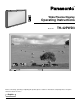
® Wide Plasma Display PLASMA DISPLAY Operating Instructions + — VOL INPUT R POWE / BY R - STAND ON G POWER Model No. R - STANDBY G POWER ON INPUT — VOL TH-42PWD3 + Before connecting, operating or adjusting this product, please read these instructions completely. Please keep this manual for future reference.
WARNING RISK OF ELECTRIC SHOCK DO NOT OPEN WARNING: To reduce the risk of electric shock do not remove cover or back. No user-serviceable parts inside. Refer servicing to qualified service personnel. The lightning flash with arrow-head within a triangle is intended to tell the user that parts inside the product are a risk of electric shock to persons.
Important Safety Instructions Power Sources This product shall be operated only from the type of power source indicated on the marking label. If you are not sure of the type of power supply to your home, consult your appliance dealer or local power company. Unplug this apparatus during lightning storms or when unused for a long period of time.
Dear Panasonic Customer Welcome to the Panasonic family of customers. We hope that you will have many years of enjoyment from your new Wide Plasma Display. To obtain maximum benefit from your set, please read these Instructions before making any adjustments, and retain them for future reference. Retain your purchase receipt also, and note down the model number and serial number of your set in the space provided on the rear cover of these instructions.
Table of Contents Important Safety Instructions ....................................... 2 FCC STATEMENT ........................................................... 6 Safety Precautions ......................................................... 7 Accessories .................................................................... 9 Accessories Supplied .................................................... 9 Optional Accessories .................................................... 9 Remote Control Batteries .......
FCC STATEMENT FCC STATEMENT This equipment has been tested and found to comply with the limits for a Class A digital device, pursuant to part 15 of the FCC Rules. These limits are designed to provide reasonable protection against harmful interference when the equipment is operated in a commercial environment. This equipment generates, uses, and can radiate radio frequency energy and, if not installed an used in accordance with the instruction manual, may cause harmful interference to radio communications.
Safety Precautions WARNING Set up Do not place the Wide Plasma Display on sloped or unstable surfaces. The Wide Plasma Display may fall off or tip over. • Do not place any objects on top of the Wide Plasma Display. If water spills onto the Wide Plasma Display or foreign objects get inside it, a short-circuit may occur which could result in fire or electric shock. If any foreign objects get inside the Wide Plasma Display, please consult an Authorized Service Center. • Do not cover the ventilation holes.
Safety Precautions CAUTION This Wide Plasma Display is for use only with the following optional accessories. Use with any other type of optional accessories may cause instability which could result in the possibility of injury. (All of the following accessories are manufactured by Matsushita Electric Industrial Co., Ltd.) ................................................... TY-SP42PWD3W • Speakers.................................................... • Pedestal ................................................
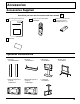
Accessories Accessories Supplied Check that you have the Accessories and items shown Operating Instruction book Remote Control Transmitter EUR646525 √ Batteries for the Remote Control Transmitter (AA(R6) Battery × 2) INPUT SURROUND VOL N R PICTURE SOUND SET UP PICTURE POS.
Remote Control Batteries Requires two AA batteries. 1. Turn the transmitter face down. Press and slide off the battery cover. 2. Install the batteries as shown in the battery compartment. (Polarity + or – must match the markings in the compartment). 3. Replace the cove and slide in reverse until the lock snaps. Two "AA" size Helpful Hint: For frequent remote control users, replace old batteries with Alkaline batteries for longer life.
Basic Controls INPUT R - STANDBY G POWER ON — VOL + TH-42PW3 Main Power On/Off Switch Power Indicator The Power Indicator will light. Power-OFF .... Indicator not illuminated (The unit will still consume some power as long as the power cord is still inserted into the wall outlet.) Stand-by .... Red Power-ON ..... Green • Input button (VIDEO (S-VIDEO)/COMPONENT, RGB/PC Mode Selection) Push the “INPUT” button to select VIDEO(S-VIDEO)/COMPONENT or RGB/PC input signal modes sequentially.
Connections SPEAKER Terminals (L) SPEAKER Terminals (R) – Cable fixing bands Secure any excess cables with bands, as required.
Connections How to connect the speakers When connecting the speakers, be sure to use only the optional accessory speakers. Refer to the speaker’s Installation Manual for details on speaker installation. 1 Speakers (Optional accessories) 2 1 2 How to connect the AV Input Terminals Connect the signal source equipment (see pages 14 to 17).
Connections How to connect the AV Input Terminals VIDEO signal connection (VCR) R Audio OUT L Video OUT VIDEO Video input to BNC socket BNC video cable AUDIO 2×RCA audio cables Audio input to L/R sockets (VCR) L AUDIO S-VIDEO R Audio OUT L VIDEO R Video OUT AV IN VIDEO Video input to BNC socket BNC video cable RCA-BNC adapter plug AUDIO 2×RCA audio cables Audio input to L/R sockets How to connect the CONTROLLER TUNER Input Terminals The CONTROLLER TUNER input terminal is reserved for use w
Connections How to connect the COMPONENT/RGB Input Terminals Component signals (Y, PB, PR) connection DVD Player L AUDIO VD R Audio OUT L HD PB PR PB/CB/B Y/G R DVD (Y,PB, PR) OUT Y PR/CR/R COMPONENT/RGB IN BNC-RCA adapter plug (not supplied) Video input to Y, PB, PR sockets Y, PB, PR 3×BNC video cables AUDIO 2×RCA audio cables Audio input to L/R sockets Notes: (1) Change the “COMPONENT/RGB-IN” setting in the “SET UP” menu to “Y/PB/PR”.
Connections How to connect the PC Input Terminals COMPUTER AUDIO PC IN POWER / R - STANDBY INPUT — VOL + G POWER ON Conversion adapter (if necessary) D-sub 15p RGB PC cable Ferrite core Less than 7" 7/8 (20 cm) Audio 1/8" (3mm) stereo plug Connect a cable which matches the audio output terminal on the computer. Notes: (1) Computer signals which can be input are those with a horizontal scanning frequency of 15.5 to 110 kHz and vertical scanning frequency of 48 to 120 Hz.
Connections How to connect the SERIAL Terminals The SERIAL terminal is used when the Wide Plasma Display is controlled by a computer. COMPUTER SERIAL 5 4 9 RS-232C cable 3 8 2 7 1 6 Pin layout for RS-232C Conversion cable D-sub 9p Notes: (1) Use the RS-232C cable to connect the computer to the Wide Plasma Display. (2) The computers shown is for example purposes only. (3) Additional equipment and cables shown are not supplied with this set.
Power ON/OFF and Input Signal Selection Power ON/OFF Connecting the plug to the Wall Outlet Push the POWER switch on the Wide Plasma Display to turn the set on POWER-ON Power Indicator: Green Example: The screen below is displayed for a while after the Wide Plasma Display is turned on. (setting condition is an example.) R - STANDBY INPUT — VOL When the POWER is turned on for the first time, the LANGUAGE selection screen is displayed.
Power ON/OFF and Input Signal Selection Select the Input Signal INPUT Press the INPUT button to select the input video signal desired from equipment such as a VCR which has been connected to the Wide Plasma Display.
On-Screen Menu Display from Remote Control To PICTURE adjust menu (see page 28) PICTURE NORMALIZE NORMAL PICTURE MENU PICTURE BRIGHTNESS COLOR TINT SHARPNESS COLOR TEMP ADVANCED SETTINGS STANDARD 0 0 0 0 0 NORMAL ON INPUT SURROUND NORMALIZE VOL RETURN ADJUST SELECT N R To ADVANCED SETTINGS menu (see page 29) ADVANCED SETTINGS NORMALIZE NORMAL BLACK EXTENSION W/B HIGH R W/B HIGH B W/B LOW R W/B LOW B GAMMA PICTURE 0 0 0 0 0 SOUND SET UP PICTURE POS. /SIZE ASPECT 2.
On-Screen Menu Display from Remote Control To SOUND adjust menu (see page 26) SOUND NORMALIZE AUDIO MENU BASS TREBLE BALACE SURROUND To SIGNAL screen for VIDEO (see page 31) NORMAL STANDARD 0 0 0 ON [ VIDEO ] SIGNAL 3D Y/C FILTER (NTSC) COLOR SYSTEM Panasonic AUTO (4:3 ) NORMALIZE ON AUTO NORMAL RETURN ADJUST SELECT To SIGNAL screen for COMPONENT (see page 32) [ COMPONENT ] SIGNAL CLAMP POSITION 1 Press to select “SIGNAL” To SET UP menu (see page 30) menu.
ASPECT Controls The Wide Plasma Display will allow you to enjoy viewing the picture at its maximum size, including wide screen cinema format picture. ASPECT INPUT VOL N R SOUND SET UP PICTURE POS. /SIZE PC ASPECT OFF TIMER PLASMA DISPLAY 22 NORMAL ZOOM Panasonic AUTO SURROUND PICTURE ASPECT button The aspect mode changes each time the ASPECT button is pressed. FULL JUST Notes: (1) During RGB and PC input signal modes, the mode switches between “NORMAL” and “FULL” only.
ASPECT Controls Picture Mode Explanation NORMAL will display a 4:3 picture at its standard 4:3 size. 4 NORMAL NORMAL 3 4 ZOOM mode magnifies the central section of the picture. 16 ZOOM ZOOM 3 9 4 FULL will display the picture at its maximum size but with sight elongation.
Adjusting PICTURE POS./SIZE Adjusting screen 1 ASPECT Press to select the screen mode to adjust (see page 23). INPUT 2 SURROUND PICTURE POS. /SIZE Press to display the PICTURE POS./ SIZE menu. VOL N R Press to select H-POS/H-SIZE/V-POS/ V-SIZE/CLOCK PHASE. PICTURE During “VIDEO” and “COMPONENT” input signal modes. During “RGB” and “PC” input signal modes. PICTURE POS./SIZE PICTURE POS.
Adjusting PICTURE POS.
SOUND Adjustment 1 Press the SOUND 2 Select to adjust each item. button to display the SOUND menu. INPUT Press to select the desired adjustment menu. SURROUND VOL Select the desired level by listening to the sound. N PICTURE R SOUND SET UP PICTURE POS S BASS Adjusts low sounds SOUND NORMALIZE AUDIO MENU BASS TREBLE BALACE SURROUND TREBLE Adjusts high sounds BALANCE Adjusts left and right volumes NORMAL STANDARD 0 0 0 ON NORMALIZE ADJUST RETURN STANDARD Emits the original sound.
SURROUND Controls SURROUND INPUT SURROUND Button The benefits of surround sound are enormous. You can be completely enveloped in sound; just as if you were at a concert hall or cinema. The surround setting switches on and off each time the SURROUND button is pressed. ON SURROUND OFF VOL N R PICTURE SOUND SET UP SURROUND PICTURE POS. /SIZE PC ASPECT ON Note: The surround settings are memorized separately for each SOUND mode (AUTO, STANDARD).
PICTURE Adjustments 1 2 PICTURE PICTURE Press the PICTURE button on the Remote Control to display the PICTURE menu. NORMALIZE NORMAL PICTURE MENU PICTURE BRIGHTNESS COLOR TINT SHARPNESS COLOR TEMP ADVANCED SETTINGS Select to adjust each item. Press to select the menu to adjust. STANDARD 0 0 0 0 0 NORMAL ON NORMALIZE ADJUST Select the desired level by looking at the picture behind the menu. Press the left modes.
PICTURE Adjustments Item Effect Adjustments PICTURE Less More BRIGHTNESS Darker Brighter Adjusts for easier viewing of dark pictures such as night scenes and black hair. Adjusts slightly to a lighter color. COLOR Less TINT (NTSC only) Selects the proper brightness and density for the room. More Adjust for nice skin color. Reddish Greenish Displays a sharp image. SHARPNESS Less More Notes: (1) “COLOR” , “TINT” and “SHARPNESS” settings cannot be adjusted for “RGB” and “PC” input signal modes.
SET UP for Input Signals COMPONENT/RGB IN SELECT Select to match the signals from the source connected to the COMPONENT/RGB input terminals. Y, PB, PR signals “COMPONENT” R, G, B, HD, VD signals “RGB” 1 SET UP Press to display the SET UP menu screen. INPUT Press to select the “COMPONENT/RGB IN SELECT”. 2 SURROUND Press to select the desired mode. VOL N SET UP R COMPONENT/RGB-IN SELECT RGB SIGNAL ENGLISH (US) OSD LANGUAGE RETURN PICTURE SOUND SELECT SET UP COMPONENT PICTURE POS.
SET UP for Input Signals COLOR SYSTEM / Panasonic AUTO Select SIGNAL from the “SET UP” menu during VIDEO (S-VIDEO) input signal mode.(“SIGNAL [VIDEO]” menu is displayed.) SET UP COMPONENT/RGB-IN SELECT Press to select the “COLOR SYSTEM” or “Panasonic AUTO”. RGB SIGNAL OSD LANGUAGE Press to select each functions.
SET UP for Input Signals Select SIGNAL from the “SET UP” menu during RGB or PC input signal mode. Press to select each item. [ COMPONENT ] SIGNAL CLAMP POSITION Press to adjust. The following operation methods are the same for both the SIGNAL [RGB] and SIGNAL [PC]. [ RGB ] SIGNAL H&V SYNC NARROW PULL-IN RANGE CLAMP POSITION H-FREQ. 31.5 kHz V-FREQ. 60.0 Hz [ PC ] SIGNAL H&V SYNC NARROW PULL-IN RANGE CLAMP POSITION H-FREQ. 31.5 kHz V-FREQ. 60.
Troubleshooting Before you call for service, determine the symptoms and make a few simple checks as shown below. Symptoms Picture Checks Sound Electrical Appliances Cars/Motorcycles Fluorescent light Interface Noisy Sound Volume (Check whether the mute function has been activated on the remote control.
Specifications TH-42PWD3 Power Source Power Consumption 120 V AC, 50/60 Hz Normal use Stand-by condition Power off condition Plasma Display panel Contrast Ratio Brightness Capability Screen size Max. Amps 4.0 A 1.9 W 0.7 W Drive method AC type 42-inch, 16:9 aspect ratio 3000:1 (Panel only) 650 / m2 (As a set) 400 / m2 920 mm (W) × 518 mm (H) × 1056 mm (diagonal) No.
Specifications TH-42PWD3 Accessories Supplied Remote Control Transmitter Batteries RCA-BNC adapter plug Ferrite core EUR646525 2 × AA Size Optional Supplied Speakers Pedestal Wall stand Mobile stand Wall-hanging bracket (vertical) TY-SP42PWD3W TY-ST42PT3-K TY-ST42PW1 TY-ST42PF3 TY-WK42PV1 Wall-hanging bracket (angled) TY-WK42PR1 Ceiling unit Terminal Cover TY-CE42PS1 TY-UPS200 Dimensions (W × D × H) 40.2” (1020 mm) × 24” (610 mm) × 3.5” (89 mm) 3.5" (89 mm) 24" (610 mm) 40.
Customer’ Record The model number and serial number of this product can be found on its back cover. You should note this serial number in the space provided below and retain this book, plus your purchase receipt, as a permanent record of your purchase to aid in identification in the event of theft or loss, and for Warranty Service purposes.