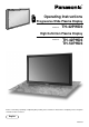
® Operating Instructions PLASMA DISPLAY VOL – + ENTER MENU INPUT POWE R / Progressive Wide Plasma Display Model No. Y R - STANDB ON G POWER TH-42PWD6 High Definition Plasma Display Model No. TH-42PHD6 TH-50PHD6 Before connecting, operating or adjusting this product, please read these instructions completely. Please keep this manual for future reference.
Dear Panasonic Customer Welcome to the Panasonic family of customers. We hope that you will have many years of enjoyment from your new Plasma Display. To obtain maximum benefit from your set, please read these Instructions before making any adjustments, and retain them for future reference. Retain your purchase receipt also, and note down the model number and serial number of your set in the space provided on the rear cover of these instructions. Visit our Panasonic Web Site http://www.panasonic.co.
Important Safety Notice WARNING: To prevent damage which may result in fire or shock hazard, do not expose this appliance to rain or moisture. Do not place containers with water (flower vase, cups, cosmetics, etc.) above the set. (including on shelves above, etc.) WARNING: 1) To prevent electric shock, do not remove cover. No user serviceable parts inside. Refer servicing to qualified service personnel. 2) Do not remove the earthing pin on the power plug.
Safety Precautions WARNING Setup This Plasma Display is for use only with the following optional accessories. Use with any other type of optional accessories may cause instability which could result in the possibility of injury. (All of the following accessories are manufactured by Matsushita Electric Industrial Co., Ltd.) • Speakers .................................................................. TY-SP42P5W-K (TH-42PWD6, TH-42PHD6), TY-SP50P5W-K (TH-50PHD6) • Pedestal ...................................
Safety Precautions If problems occur during use If a problem occurs (such as no picture or no sound), or if smoke or an abnormal odour starts to come out from the Plasma Display, immediately unplug the power cord plug from the wall outlet. If you continue to use the Plasma Display in this condition, fire or electric shock could result. After checking that the smoke has stopped, contact your local Panasonic dealer so that the necessary repairs can be made.
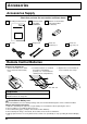
Accessories Accessories Supply Check that you have the accessories and items shown Operating Instruction book Remote Control Transmitter EUR646529 Batteries for the Remote Control Transmitter (2 × R6 Size) INPUT SURROUND VOL N R PICTURE MULTI PIP SET UP SOUND SWAP SELECT PICTURE POS. /SIZE PC MOVE ASPECT OFF TIMER PLASMA DISPLAY AC cord Fixing bands Ferrite core (small size) × 1 Ferrite core (large size) × 2 Remote Control Batteries Requires two R6 batteries. 1.
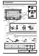
Connections When connecting the speakers, be sure to use only the optional accessory speakers. Refer to the speaker’s Installation Manual for details on speaker installation. 1 (Example: TH-42PWD6) Speakers (Optional accessories) 2 1 2 SPEAKERS Terminals (L) SPEAKERS Terminals (R) AC cord connection (see page 12) – AC cord fixing 1. Open the clamper. Clamper 2. Insert the AC cord and close the clamper securely. 3. Slide up the clamper and fix the AC cord plug securely.
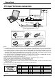
Connections PC Input Terminals connection COMPUTER AUDIO PC IN R - STANDBY G POWER ON Conversion adapter (if necessary) INPUT MENU - VOL + ENTER Less than 3" 15/16 (10 cm) Ferrite core (large size) (supplied) D-sub 15p RGB PC cable Less than 3" 15/16 (10 cm) Ferrite core (small size) (supplied) Audio Stereo plug Connect a cable which matches the audio output terminal on the computer.
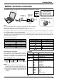
Connections SERIAL Terminals connection The SERIAL terminal is used when the Plasma Display is controlled by a computer. COMPUTER 6 1 RS-232C Straight cable Ferrite core (large size) (supplied) SERIAL 7 2 8 3 9 4 5 Pin layout for RS-232C Installing the ferrite core (Large size) Less than 3" 15/16 (10 cm) D-sub 9p Open Notes: (1) Use the RS-232C cable to connect the computer to the Plasma Display. (2) The computer shown is for example purposes only.
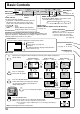
Basic Controls INPUT R - STANDBY G POWER ON Main Power On/Off Switch - VOL + MENU ENTER Enter/Aspect button (see page 14, 16) TH-42PWD6 Remote control sensor MENU Screen ON/OFF Power Indicator Each time the MENU button is pressed, the menu The Power Indicator will light. screen will switch. (see page 14) Power-OFF .. Indicator not illuminated (The unit Normal Viewing Picture Set up will still consume some power as long as the Sound Picture Pos.
Basic Controls Stand-by (ON/OFF) button The Plasma Display must first be plugged into the wall outlet and turned on at the power switch (see page 12). Press this button to turn the Plasma Display On, from Stanby mode. Press it again to turn the Plasma Display Off to Stanby mode. SURROUND Button The benefits of surround sound are enormous. You can be completely enveloped in sound; just as if you were at a concert hall or cinema.
Power On/Off and input signal selection AC cord connection Connecting the AC cord plug to the Plasma Display. Fix the AC cord plug securely to the Plasma Display with the clamper. (see page 7) Power On/Off Connecting the plug to the Wall Outlet Note: Main plug types vary between countries. The power plug shown at left may, therefore, not be the type fitted to your set. R - STANDBY INPUT MENU – VOL + Press the Power switch on the Plasma Display to turn the set on: Power-On.
Power On/Off and input signal selection Select the input signal INPUT Press the INPUT button to select the input signal to be played back from the equipment which has been connected to the Plasma Display. Select the input signals to be connected by installing the optional Terminal Boards.
On-Screen Menu Displays To Picture adjust menu (see page 18) The MENU button on the unit can also be pressed. INPUT Picture Normal Normalise Picture Mode Contrast Brightness Colour Tint Sharpness White balance Advanced settings MENU – VOL + Press to select. 1 ENTER Normal 25 0 0 0 0 Each time the MENU button is pressed, the menu screen will switch. Normal On Normal Viewing Picture Set up Sound Picture Pos./ Size [ from the unit ] INPUT MENU – VOL + ENTER 2 1 Press to select “On”.
On-Screen Menu Displays [ from the unit ] Press to access each adjust screen. 2 INPUT MENU – VOL + R ENTER Press to return to previous menu screen. To Signal screen for AV(S Video) (see page 30, 31) [ AV ] Signal 3D Y/C Filter (NTSC) Colour system Cinema reality Panasonic Auto (4:3 ) On Auto Off 4:3 To Signal screen for Component (see page 31) Press the R button to return to previous menu screen.
ASPECT Controls The Plasma Display will allow you to enjoy viewing the picture at its maximum size, including wide screen cinema format picture. ASPECT button ASPECT The aspect mode changes each time the 4:3 Zoom 16 : 9 ASPECT button is pressed. Panasonic Auto Just [from the unit] INPUT SURROUND VOL N R INPUT PICTURE MULTI PIP ENTER The aspect mode changes each time the ENTER button is pressed. ZOOM MOVE SELECT PICTURE POS.
Adjusting Picture Pos./Size Adjusting screen 1 INPUT PICTURE POS. /SIZE SURROUND VOL Press to display the Picture Pos./Size menu. Press to select H-Pos/H-Size/V-Pos/VSize/Clock Phase. 2 N R PICTURE MULTI PIP SWAP PICTURE POS. /SIZE PC During “AV(S Video)” and “Component” input signal. During “RGB/PC” and “DVI” input signal. Picture Pos./Size Picture Pos./Size Normalise H-Pos H-Size V-Pos V-Size Normal Normalise H-Pos H-Size V-Pos V-Size Clock Phase Normal 3 Press to adjust Pos./Size.
Picture Adjustments 1 PICTURE Press to display the Picture menu. Picture 2 Select to adjust each item. Press to select the menu to adjust. Select the desired level by looking at the picture behind the menu. Press the left modes.
Picture Adjustments Item Effect Adjustments Contrast Less More Brightness Darker Brighter Selects the proper brightness and density for the room. Adjusts for easier viewing of dark pictures such as night scenes and black hair. Adjusts colour saturation. Colour Less More Reddish Greenish Less More Adjust for nice skin colour. Tint Adjusts picture sharpness. Sharpness Notes: (1) “Colour” and “Tint” settings cannot be adjusted for “RGB/PC” and “DVI” input signal.
Sound Adjustment 1 SOUND Press to display the Sound menu. INPUT SURROUND 2 Select to adjust each item. VOL Press to select the desired adjustment menu. N R Select the desired level by listening to the sound. PICTURE MULTI PIP Bass Adjusts low sounds Treble Adjusts high sounds Balance Adjusts left and right volumes Sound Normalise Sound Mode Bass Treble Balance Surround Normal Normal SOUND SWAP SET UP SELECT ZOOM MOVE Emits the original sound.
Digital Zoom This displays an enlargement of the designated part of the displayed image. 1 Display the "Operation Guide". MOVE Press to access Digital Zoom. Exit 1 The “Operation Guide” will be displayed. INPUT SURROUND VOL N R SURROUND button • During Digital Zoom, only the following keys can be operated. MUTE button VOL button INPUT R - STANDBY G POWER ON MENU – VOL + ENTER TH-42PWD6 PICTURE MULTI PIP PICTURE POS.
PRESENT TIME Setup / Set up TIMER The timer can switch the Plasma Display On or Off. Before attempting Timer Set, confirm the PRESENT TIME and adjust if necessary. Then set POWER ON Time / POWER OFF Time. 1 SET UP Press to display the Setup menu screen. INPUT Setup 1/2 Component/RGB-in select RGB RGB1 SURROUND 2 VOL N PICTURE MULTI Press to select Set up TIMER or PRESENT TIME Setup. R SOUND Press to display the Set up TIMER screen or PRESENT TIME Setup screen.
PRESENT TIME Setup / Set up TIMER Set up TIMER Display the Set up TIMER screen. Press to select POWER ON Time / POWER OFF Time. 1 Set up TIMER PRESENT TIME Press to set up POWER ON Time / POWER OFF Time. button: Forward button: Back POWER ON Function POWER ON Time POWER OFF Function POWER OFF Time 2 : 30 Off 0 : 00 Off 0 : 00 Notes: • Pressing “ ” or “ ” button once changes POWER ON Time / POWER OFF Time 1minute.
Screensaver (For preventing after-images) Do not display a still picture, especially in 4:3 mode, for any length of time. If the display must remain on, a Screensaver should be used. 1 SET UP Press to display the Setup menu screen. Setup Press to select the Screensaver. 2 1/2 Component/RGB-in select RGB RGB1 Input label Signal Screensaver Off On Off English (UK) Power save Standby save Power management OSD Language Press to select the Screensaver screen.
Screensaver (For preventing after-images ) Setup of Screensaver Time After selecting Time Designation or Interval, the relevant Time Setup will become available for selection and the Operating Time may be set. (Time cannot be set when “Mode” is “on” or “off.
Screensaver (For preventing after-images ) Side Panel Adjustment side panel Do not display a picture in 4:3 mode for an extended period, as this can cause an after-image to remain on the side panels either side of the display field. To prevent the appearance of such an after-image, illuminate the side panels. 4:3 Screen Display after-images This function may be applicable to the non-picture area. Non picture area A Picture out Picture 1 B Picture and Picture To display the Screensaver screen.
Reduces power consumption • Power save: When this function is turned On, luminous level of the plasma display is suppressed, so power consumption is reduced. • Standby save: When this function is turned On, power consumption of the microcomputer is reduced during power supply standby (see page 10, 11, 12), so standby power of the set is reduced. • Power management: The unit power supply is turned On or Off depending on whether or not there is a signal during PC input mode.
Setup for MULTI DISPLAY By lining up Plasma Displays in groups of 4 or 9 as illustrated below, an enlarged picture may be displayed across all screens. For this mode of operation, each plasma display has to be set up with a Display number to determine its location. group of 4 (2×2) group of 9 (3×3) How to Setup MULTI DISPLAY 1 SET UP Press to display the Setup menu screen. Setup INPUT SURROUND 2 VOL N Press to select the MULTI DISPLAY Setup.
Setup for MULTI DISPLAY How to set the display location number for each Plasma Display 4 Press to select Ratio (2nd step). MULTI DISPLAY Setup Press to select “2×2”, “3×3”. MULTI DISPLAY Setup Ratio Location 5 On 2 2 A1 Press to select Location. MULTI DISPLAY Setup Press to select the required arrangement number.
Setup for Input Signals Component/RGB-in Select Select the input signals to be connected by installing the Optional Terminal Board. (Refer to the Operating Instructions for the optional Terminal Board.) Select to match the signals from the source connected to the Component/RGB input terminals. “Component” Y, PB, PR signals R, G, B, HD, VD signals “RGB” 1 SET UP Press to display the Setup menu screen. INPUT Press to select the “Component/RGB-in Select”.
Setup for Input Signals Colour system / Panasonic Auto Select Signal from the “Setup” menu during AV(S Video) input signal. (“Signal [AV]” menu is displayed.) Setup 1/2 Component/RGB-in select RGB RGB1 Press to select the “Colour System” or “Panasonic Auto”. Input label Press to select each functions.
Setup for input signals Sync Select Signal from the “Setup” menu during RGB input signal. Setup Press to adjust. 1/2 Component/RGB-in select RGB RGB1 Input label Signal Screensaver Power save Standby save Power management OSD Language Press Off On Off English (UK) (ACTION) button R Press to exit from adjust mode. [ RGB ] Signal H&V Sync H-Freq. V-Freq. 31.5 kHz 60.0 Hz Note: Sync cannot be adjusted while a DVI signal is being applied.
Troubleshooting Before you call for service, determine the symptoms and make a few simple checks as shown below. Symptoms Picture Checks Sound Electrical Appliances Cars/Motorcycles Fluorescent light Interference Noisy Sound Volume (Check whether the mute function has been activated on the remote control.
Input signal can be displayed Applicable input signals for PC Input (D-sub 15P) (∗ Mark) Horizontal frequency (kHz) 525 (480) / 60i 15.73 525 (480) / 60p 31.47 625 (575) / 50i 15.63 625 (575) / 50p 31.25 750 (720) / 60p 45.00 750 (720) / 50p 37.50 1,125 (1,080) / 60i 33.75 1,125 (1,080) / 50i 28.13 1,125 (1,080) / 24p 27.00 1,125 (1,080) / 24sF 27.00 1,250 (1,080) / 50i 31.25 640 × 400 @70 Hz 31.47 640 × 480 @60 Hz 31.47 Macintosh13” (640 × 480) 35.00 640 × 480 @75 Hz 37.50 852 × 480 @60 Hz 31.
Specifications TH-42PWD6 (No.of pixels) Operating condition Temperatuer Humidity Applicable signals Colour System Scanning format PC signals Connection terminals PC SERIAL SPEAKERS (6 Ω) Accessories Supplied Remote Control Transmitter Batteries Fixing bands Ferrite core Dimensions (W × H × D) 265 W 335 W 445 W Save off 1.8 W, Save on 0.8 W Save off 1.9 W, Save on 1.1 W Save off 1.9 W, Save on 1.1 W 0.6 W 0.4 W 0.
Customer’s Record The model number and serial number of this product can be found on its back cover. You should note this serial number in the space provided below and retain this book, plus your purchase receipt, as a permanent record of your purchase to aid in identification in the event of theft or loss, and for Warranty Service purposes. Model Number Serial Number Matsushita Electric Industrial Co., Ltd. Web Site : http://www.panasonic.co.