Model No. TH-50LFB70U TH-65LFB70U TH-50LFB70E TH-65LFB70E TH-50LFB70W TH-65LFB70W Operating Instructions Display Operations Touch Screen LCD Display (for business use) English Please read these instructions before operating your set and retain them for future reference.
Dear Panasonic Customer Welcome to the Panasonic family of customers. We hope that you will have many years of enjoyment from your new LCD Display. To obtain maximum benefit from your set, please read these Instructions before making any adjustments, and retain them for future reference. Retain your purchase receipt also, and note down the model number and serial number of your set in the space provided on the rear cover of these instructions. Visit our Panasonic Web Site http://panasonic.
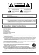
CAUTION RISK OF ELECTRIC SHOCK DO NOT OPEN WARNING: To reduce the risk of electric shock, do not remove cover or back. No user-serviceable parts inside. Refer servicing to qualified service personnel. The lightning flash with arrow-head within a triangle is intended to tell the user that parts inside the product are a risk of electric shock to persons.
FCC STATEMENT This equipment has been tested and found to comply with the limits for a Class B digital device, pursuant to Part 15 of the FCC Rules. These limits are designed to provide reasonable protection against harmful interference in a residential installation. This equipment generates, uses and can radiate radio frequency energy and, if not installed and used in accordance with the instructions, may cause harmful interference to radio communications.
Important Safety Notice WARNING 1) To prevent damage which may result in fire or shock hazard, do not expose this appliance to dripping or splashing. Do not place containers with water (flower vase, cups, cosmetics, etc.) above the set. (including on shelves above, etc.) No naked flame sources, such as lighted candles, should be placed on / above the set. 2) To prevent electric shock, do not remove cover. No user serviceable parts inside. Refer servicing to qualified service personnel.
Safety Precautions WARNING Setup This LCD Display is for use only with the following optional accessories. Use with any other type of optional accessories may cause instability which could result in the possibility of injury. (All of the following accessories are manufactured by Panasonic Corporation.) • Pedestal .................................................................................... TY-ST42P50 (for 50 inch model)*, TY-ST65P20 (for 65 inch model) • Mobile stand for Display .....................
Safety Precautions When using the LCD Display The Display is designed to operate on 110 - 127 or 220 - 240 V AC, 50/60 Hz. Do not cover the ventilation holes. • Doing so may cause the Display to overheat, which can cause fire or damage to the Display. Do not stick any foreign objects into the Display. • Do not insert any metal or flammable objects into the ventilations holes or drop them onto the Display, as doing so can cause fire or electric shock. Do not remove the cover or modify it in any way.
Safety Precautions CAUTION When using the LCD Display Do not bring your hands, face or objects close to the ventilation holes of the Display. • Heated air comes out from the ventilation holes at the top of Display will be hot. Do not bring your hands or face, or objects which cannot withstand heat, close to this port, otherwise burns or deformation could result. Be sure to disconnect all cables before moving the Display.
Safety Precautions Touch panel Carefully observe the following instructions as the display has an optical touch panel. Do not expose the display to direct sunlight or strong light source during use. • Otherwise malfunction may occur since the optical touch panel of the display uses infrared rays. After turning on the power of the display, do not touch the IR transmission part and the screen until any image is displayed.
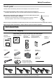
Accessories Contents in the CD-ROM The contents below are included in the supplied CD-ROM. Instruction (PDF) Software Operating Instructions - Display Operations Operating Instructions - Network Operations Operating Instructions - Wireless Manager ME Software license GNU GENERAL PUBLIC LICENSE GNU LESSER GENERAL PUBLIC LICENSE WhiteBoard Software (Windows) Allows the display to be used as whiteboard. You can run the software directly from external storage without installing it in your computer.
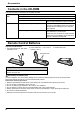
Accessories Mounting Pen Stand Mounting position of the Pen Stand [For 50 inch model] The supplied Pen Stand can be mounted in one of the four dedicated screw hole positions on the back of the Display. Each hole is marked with a circle. [For 65 inch model] The supplied Pen Stand can be mounted in one of the nine positions on the back of the Display. Remove one screw fixing the back cover and mount the Pen Stand. Remove one screw from the back cover.
Connections AC cord connection and fixing, cable fixing AC cord fixing Unplug the AC cord Plug the AC cord into the display unit. Plug the AC cord until it clicks. Note: Make sure that the AC cord is locked on both the left and right sides. Unplug the AC cord pressing the two knobs. Note: When disconnecting the AC cord, be absolutely sure to disconnect the AC cord plug at the socket outlet first.
Connections Speaker connection Please use 8 Ω/10 W speaker. Black Red 1 While pressing the lever, Red Black 2 Return the lever. insert the core wire. Video equipment connection SLOT: Terminal board (optional accessories) insert slot (see page 4) Note: The right side slot is for terminal board with 2-slot width. The terminal board with 1-slot width does not function when installed in the right side slot.
Connections VIDEO and COMPONENT / RGB IN connection Note: Additional equipment, cables and adapter plugs shown are not supplied with this set. L R Stereo mini plug (M3) AUDIO OUT VIDEO OUT Pin-BNC Adapter plug VCR Notes: AUDIO 1 IN: Shared with VIDEO and COMPONENT/RGB IN • Change the “Component/RGB-in select” setting in the “Setup” menu to “Component” (when Component signal connection) or “RGB” (when RGB signal connection).
Connections DVI-D IN connection Shared with PC IN. PC with DVI-D video out Stereo mini plug (M3) Less than Ferrite core Less than 1.97 inch (5 cm) (supplied) 1.97 inch (5 cm) DVI-video cable (Within 5 m) Installing the Ferrite core 1. 2. Pull back the tabs (in two places) Open the Ferrite core DVI-D Input Connector Pin Layouts 1 Pin No. 8 9 16 17 24 Connection port view 3. 1 2 3 4 5 6 7 8 9 10 11 12 4.
Connections PC Input Terminals connection Shared with DVI-D IN. COMPUTER Conversion adapter (if necessary) (Female) Mini D-sub 15p RGB PC cable Audio (Male) Stereo mini plug (M3) Connect a cable which matches the audio output terminal on the computer. Notes: • With regard to the typical PC input signals that are described in the applicable input signals list (see page 85), adjustment values such as for the standard picture positions and sizes have already been stored in this unit.
Connections SERIAL Terminals connection The SERIAL terminal is used when the Display is controlled by a computer. Note: To use serial control for this unit, make sure to set the “Control I/F Select” in the “Network Settings” menu to “RS-232C”. (refer to “Operating Instructions, Network Operations”) (Male) COMPUTER 9 5 8 4 7 3 6 2 1 Pin layout for SERIAL Terminal RS-232C Straight cable (Female) D-sub 9p Notes: • Use the RS-232C straight cable to connect the computer to the Display.
Connections PC OUT connection The image being reproduced on the display including the image input from video equipment and the contents drawn on the whiteboard can be displayed on another sub monitor. To use the function, set “Monitor Out” to “On” in “Setup”. (see page 66) Note: Setting it to “On” will adjust the “Picture” menu values to the standard values.
Connections Example connection using the DIGITAL LINK Terminal A twisted pair cable transmitter such as the Panasonic Digital Interface Box (ET-YFB100G) uses twisted pair cables to transmit inputted video and audio signals, and these digital signals can be input to the Display via the DIGITAL LINK terminal.
Power On / Off Connecting the AC cord plug to the Display. Connecting the plug to the Wall Outlet Notes: • Main plug types vary between countries. The power plug shown at right may, therefore, not be the type fitted to your set. • When disconnecting the AC cord, be absolutely sure to disconnect the AC cord plug at the socket outlet first. Power switch Press the Power switch on the Display to turn the set on: Power-On.
Power On / Off When first switching on the unit Following screen will be displayed when the unit is turned on for the first time. Use the remote control to make the settings. Pressing the buttons on the main unit or multi-touch operation will not work. OSD Language OSD Language English (UK) Deutsch Français Day/Time Settings Select the language. 2 Set. 1 Italiano Time MON 99:99 Set Day MON Time 18:00 Español ENGLISH (US) Day/Time Settings Time TUE 99:99 Set Русский Select “Day” or “Time”.
Selecting the input signal Press to select the input signal to be played back from the equipment which has been connected to the Display. Alternatively you can press , press to select the input and press .
Basic Controls Main Unit Touch panel IR transmission part Installed on the four sides of the display panel. Remote control sensor Power Indicator The Power Indicator will light. • Power-OFF .... Indicator not illuminated (The unit will still consume some power as long as the power cord is still inserted into the wall outlet.) • Standby ........ Red Orange (When “Slot power” is set to “On” and Terminal Board is installed.
Basic Controls Remote Control Transmitter ACTION button Press to make selections. ASPECT button Press to adjust the aspect. (see page 23) Standby (ON / OFF) button The Display must first be plugged into the wall outlet and turned on at the power switch (see page 18). Press this button to turn the Display On, from Standby mode. Press it again to turn the Display Off to Standby mode. POS./SIZE button (see page 48) PICTURE button (see page 51) Sound mute On / Off Press this button to mute the sound.
ASPECT Controls The Display will allow you to enjoy viewing the picture at its maximum size, including wide screen cinema format picture. Note: Be aware that if you put the display in a public place for commercial purposes or a public showing and then use the aspect mode select function to shrink or expand the picture, you may be violating the copyright under copyright law.
Digital Zoom This displays an enlargement of the designated part of the displayed image. 1 Display the operation guide. Exit Press to access Digital Zoom. The operation guide will be displayed. 1 During Digital Zoom, only the following buttons can be operated. [Remote control] OFF TIMER button [Unit] ENTER/ VOL button +/ MUTE button VOL button VOL -/ POSITION / ACTION button 2 Select the area of the image to be enlarged. Press on the enlargement location to select. The cursor will move.
MULTI PIP You can display two pictures, such as a video image and computer image, in a two-screen display. Notes: • If “Input lock” in Options menu is set to other than “Off”, two screen display function isn’t available (see page 73). • 2k1k signals that are received with the Dual Link HD-SDI Terminal Board (TY-FB11DHD) cannot be displayed in two-screen display. MULTI PIP Settings Set the functions and mode for two-screen display in “MULTI PIP Settings” in the Setup menu.
Multi-touch Operation The built-in touch panel function of the display enables the screen control with a finger or the supplied pen. This section explains about the multi-touch operation on the display main unit. Note: To enable multi-touch operation, select “Setup” - “Touch Screen Settings” and set “Touch Screen” to “On”. (see page 59) Touch gestures You can use the following touch operations.
Multi-touch Operation Name Operation Zoom in Pinch out with two fingers Touch Zoom operation Enlarging the image. Zoom out Pinch in with two fingers Touch Zoom operation Shrinking the image.
Multi-touch Operation Control menu Displaying the control menu Control menu INPUT HDMI1 HDMI2 SLOT INPUT VIDEO COMPONENT PC DVI DIGITAL LINK Miracast(TM) Panasonic APPLICATION MEMORY VIEWER WHITEBOARD Display Settings Picture Sound Pos./Size Setup Recall Volume Swipe from the screen edge. 16 Swiping from the right edge of the screen will display the control menu on the right. Swiping from the left edge will display the control menu on the left.
Touch Zoom You can enlarge or shrink the picture with touch operation. 1 INPUT HDMI1 HDMI2 SLOT INPUT Swipe from the screen edge to display the control menu. VIDEO COMPONENT PC DVI DIGITAL LINK Miracast(TM) Control menu see page 28 Panasonic APPLICATION MEMORY VIEWER WHITEBOARD Display Settings Picture Sound Control menu Pos./Size Setup Recall Volume 16 2 Tap . The Touch Zoom mode is now active. Zoom in 3 Zoom in the part you want to enlarge. Touch the screen with two fingers and pinch out.
Memory Viewer Function The Memory Viewer function makes it is possible to display the video and pictures which are stored in the USB memory when the USB memory is inserted into the display. What you can display with the Memory Viewer function The following files are supported. Picture Video Extension Format jpg/jpeg Maximum resolution: 8000 × 8000 bmp Maximum resolution: 8000 × 8000 support: 1, 4, 8, 16, 24, 32 bit Extension Video codec Audio codec mov H.
Memory Viewer Function Inserting the USB memory Insert the USB memory to the USB (VIEWER) port on the side of the display. USB (VIEWER) USB MEMORY Notes: • When inserting the USB memory, confirm the direction of the plug not to damage the terminal. • Please note following points to insert and remove the USB memory. • The indicator of the inserted USB memory will be blinking while the display is reading out the data. Do not remove the USB memory while it is blinking.
Memory Viewer Function Displaying the Memory Viewer screen Remote control operation Press Touch operation to select the MEMORY VIEWER input. Tap MEMORY VIEWER in the control menu. MEMORY VIEWER If “INPUT (MEMORY VIEWER)” has been assigned to a FUNCTION button, simply pressing it can switch the Control menu see page 28 input to MEMORY VIEWER. (see page 65) The thumbnails or the file list is displayed.
Memory Viewer Function Playing the pictures - Remote control Moves between the folder list and thumbnails Select a file in the same manner in the file list view. Folder list to select the desired folder. Press 1 The selected folder opens. Thumbnails / File list 2 Press to select the desired file. Press @@ to return to the folder list. 3 Press . The picture will be displayed on the full screen. Remote control operation guide Press the remote control buttons to perform the following operations.
Memory Viewer Function Playing the video - Remote control Select the desired file in the same manner as “Playing the pictures - Remote control”. (see page 33) Folder list to select the desired folder. Press 1 The selected folder opens. Thumbnails / File list 2 Press Press to select the desired file. to return to the folder list. 3 Press . The video will be displayed on the full screen.
Memory Viewer Function Playing the pictures - Touch operation Tap to open the folder Tap to switch the see page Double-tap to start playing Select a file in the same manner in the file list view. Tap the desired folder in the folder list. 1 The selected folder opens. 2 Tap to select the desired file. Double-tap the selected file. 3 The picture will be displayed on the full screen. Touch operation icons Tap to perform the following operations.
Memory Viewer Function Playing the video - Touch operation Select the desired file in the same manner as “Playing the pictures - Touch operation”. (see page 35) Tap the desired folder in the folder list. 1 The selected folder opens. 2 Tap to select the desired file. Double-tap the selected file. 3 The video will be displayed on the full screen. Fast-forward / Rewind / Pause indication Touch operation icons Tap to perform the following operations.
Using Built-in WhiteBoard The built-in WhiteBoard allows you to use the display as whiteboard and perform pen drawing such as marking on the on-screen image. About the built-in WhiteBoard • To enable pen drawing, select “Setup” - “Touch Screen Settings” and set “Touch Screen” to “On”. (see page 59) • Use a finger or the supplied pen to perform pen drawing. • Up to four people can draw at the same time.
Using Built-in WhiteBoard Transparent mode (Drawing on video and still image) Drawing will be made on the image of the computer or HDMI input shown on the display. 1 With any other input than WHITEBOARD, swipe from the screen edge to display the control menu. Control menu see page 28 2 Tap . The display enters the transparent mode allowing you to draw on video or still image. To display the main menu Main menu Tap to display the main menu for pen drawing.
Using Built-in WhiteBoard Main menu Tap the function button of the main menu to activate the desired function. The function buttons displayed differ depending on the mode. Main menu display The main menu will appear on the side where you tap shown in the right or left of the screen. Main menu Main menu Tap to hide the pen tool. Mode selection / Split screen see page 41 Undo / Redo Undo the previous action or redo the canceled action. Marker Draw a freeform line such as a text and figure.
Using Built-in WhiteBoard How to perform pen drawing Select the desired function before starting drawing. Note: Always use a finger or the supplied pen to perform pen drawing. Do not use a hard or sharp tip such as nail, ball-point pen, and pencil. On the whiteboard, up to four people can draw at the same time. The pen color, pen thickness and other preferences selected in the main menu will be shared. Pen (supplied) Changing the pen color 1 Tap “Marker” or “Line”.
Using Built-in WhiteBoard Selecting the mode Tap “Mode selection” of the main menu to switch the drawing mode. Switches to the Whiteboard mode. The input does not switch to WHITEBOARD. Switches to the transparent mode. Mode selection Notes: • When the input is WHITEBOARD, only the WhiteBoard mode can be used. It is not possible to change the mode. • When you change the mode, a message will appear asking if you save the contents drawn before the change. Save them as a file as necessary.
Using Built-in WhiteBoard Saving pen drawing content (Page Menu) Page Menu will be enabled in the WhiteBoard mode or during drawing on the captured image. The drawn content and its background can be saved in the built-in memory or USB memory and can be read as a see page. Connect a USB memory to the USB (VIEWER) terminal on the side of the display. USB Memory see page 30 Notes: • To use the built-in memory, select “Setup” - “Touch Screen Settings” and set “Built-in MEMORY SETTING” to “On”.
Using Built-in WhiteBoard Sending the pen drawing content by e-mail It is possible to send the pen drawing content and the background image together as an attached file of e-mail. Note: E-mails cannot be sent while in the transparent mode. Setting the destination address You need to specify the destination address and subject using the Web Browser function of the display. For details, see page 32 of Operating Instructions - “Network Operations”.
Using WhiteBoard Software The “WhiteBoard software” included in the supplied CD-ROM allows you to perform various functions in addition to pen drawing, such as controlling computer's desktop with touch gestures. Preparation Connect the computer to the USB (TOUCH) terminal on the side of the display with the supplied USB cable. 1 Computer USB (TOUCH) USB cable (supplied) the computer to the video input terminal on the display. 2 Connect Connect to one of the following input terminals.
Using Miracast(TM) The function allows the image shown on the smartphone or tablet device to be sent and displayed on the display. the Miracast(TM) input. 1 Select The display switches to the [Miracast(TM)] screen and the standby screen will be displayed. Start the Miracast application on the Miracast-compatible device or computer 2 Connect the device of the name shown on the display. The name of the Miracast application and how to start it may differ depending on the device model.
On-Screen Menu Displays Remote Control Unit 1 Display the menu screen. ENTER/ Press. Display Settings Picture Press to select. (Example: Picture menu) + Sound / Pos./Size VOL - Setup / Recall MENU 2 Select the item. Select. Picture Normalise ENTER/ Press several times. Press. Normal Normal Picture Mode Backlight + 100 Contrast 100 Brightness 50 Colour 50 Hue 50 Sharpness 5 White balance / VOL - Select.
On-Screen Menu Displays Menu operation with multi-touch gestures 1 Swipe from the screen edge to display the control menu Control menu see page 28 2 Tap the desired menu The selected menu screen is displayed. Display Settings Picture Sound Pos./Size Setup Recall 3 Tap the desired item Sound Tap [Back] to return to the previous screen.
Adjusting Pos./Size 1 Press to display the Pos./Size menu. Pos./Size Normalise 2 3 Press to select the menu to adjust. Normal Auto Setup Press to adjust the menu. H-Pos 0 H-Size 0 V-Pos 0 V-Size 0 Dot Clock 0 Clock Phase 0 Clamp Position 0 1:1 Pixel Mode 4 Press to exit from adjust mode. Off Note: Unadjustable items are grayed out. Adjustable items differ depending on the input signal and the display mode. Notes: • Pos./Size cannot be adjusted with two screen display.
Adjusting Pos./Size Notes: • If the dot clock frequency of an analog signal is 162 MHz or higher, “Dot Clock” and “Clock Phase” cannot be automatically corrected. • When digital signal input, Dot Clock and Clock Phase cannot be made. • Auto Setup may not work when a cropped or dark image is input. In such case, switch to a bright image with borders and other objects are clearly shown, and then try auto setup again. • Depending on the signal, out of alignment may occur after Auto Setup.
Adjusting Pos./Size Clamp Position (During Component/PC input signal) Adjusts the clamp position when black parts of the image have no detail due to underexposure or are tinged with green. Optimum value for Clamp Position adjustment When black parts have no detail due to underexposure (blackout) → Value that causes least blackout is the optimum. When black parts are tinged with green → Value that cancels the greenishness without causing blackout is the optimum.
Picture Adjustments 1 2 Press to display the Picture menu. Select to adjust each item. Press to select the menu to adjust. Select the desired level by looking at the picture behind the menu. Note: Menu that cannot be adjusted is grayout. Adjustable menu changes depending on signal, input and menu setting. Picture Normalise Press “ ” or “ ” button to switch between modes.
Picture Adjustments Item Backlight Contrast* Brightness Colour Hue Sharpness Effect Adjustments Darker Brighter Adjusts luminance of the back light. Less More Selects the proper brightness and density for the room. Darker Brighter Less More Reddish Greenish Less More Adjusts for easier viewing of dark pictures such as night scenes and black hair. Notes: • You can change the level of each function (Contrast, Brightness, Colour, Hue, Sharpness) for each Picture Mode.
Picture Profiles Up to 8 combinations of picture adjustment values (in the Picture menu and Advanced settings) can be stored in the display memory as profiles and applied as needed, for a convenient way to enjoy your preferred picture settings.
Picture Profiles Saving profiles Follow these steps to save picture adjustment values as profiles. 1 Specify the picture quality in the Picture menu and Advanced settings. (see page 51, 52) 2 In the Picture menu, select “Memory save”. 1 select Memory save Memory load 2 access Memory edit 3 5 MEMORY1█ A B C N O P a b c n o p 0 1 2 ! ” # _ ` | Select a profile name for saving the picture adjustment values. 1 select Memory save 1. [ 2. [ ] MEMORY1 ] MEMORY2 3. [ 4. [ ] ] MEMORY3 5. [ 6.
Picture Profiles Loading profiles Load profiles and apply the picture adjustment values to the display as follows. Note: Loaded profiles are stored in memory according to the selected input terminal. (see page 20) 1 In the Picture menu, select “Memory load”. 1 select Memory save Memory load 2 2 access Memory edit Select the profile to load. 1 select Memory load 1. [ 2. [ ] MEMORY1 ] MEMORY2 3. [ ] MEMORY3 2 set PC 16:9 When profile is being loaded, profile name is displayed.
Sound Adjustment 1 2 Sound Press to display the Sound menu. Normalise Normal Speaker Select to adjust each item. Internal Sound Mode Press to select the menu to adjust. Select the desired level by listening to the sound. Normal Bass 0 Mid 0 Treble 0 Balance 0 Surround Off Audio Out (PIP) 3 Main Press to exit from adjust mode. Item Speaker Sound Mode Bass Mid Treble Balance Surround Details Select the audio output.
Setup menu 1 Press to display the Setup menu. Setup Press to select the menu to adjust. 2 Touch Screen Settings MULTI PIP Settings Network Settings Memory Viewer Settings Signal Screensaver Press to adjust the menu. 3 ECO Mode settings Input label Function Button Settings On/Off Timer Settings Day/Time Settings 4 Component/RGB-in select Press to exit from adjust mode. Monitor Out No activity power off Menu Display Duration Press to return to the previous menu.
Day/Time Settings / On/Off Timer Settings The timer can switch the Display On or Off. Before attempting Timer Set, confirm the Time and adjust if necessary. Then set POWER ON Time / POWER OFF Time. 1 2 Press to display the Setup menu. Press to select On/Off Timer Settings or Day/Time Settings. Press to display the On/Off Timer Settings screen or Day/Time Settings screen. Day/Time Settings 1 2 Press to select Day or Time. Day/Time Settings Press to setup Day or Time.
Touch Screen Settings Sets the multi-touch function and built-in WhiteBoard. Select “Touch Screen Settings” in “Setup” menu and press button. Touch Screen Settings Touch Screen On Flick menu bar On WHITEBOARD Settings Quick Launch On Initial Background White Auto Save Off Built-in Memory Setting Touch Screen To enable the multi-touch function, set this to “On”. When this is set to “On”, “WHITEBOARD Settings” are enabled. Flick menu bar On: Enables to display the control menu with swipe.
MULTI PIP Settings Set the two screen display function. MULTI PIP (page 25) Two screen display function Select “MULTI PIP Settings” in “Setup” menu and press button. MULTI PIP Settings MULTI PIP On PIP Mode Pic in Pic Main input COMPONENT Sub input VIDEO 1 Sub screen size Sub screen position Lower right Swap MULTI PIP Set this “ON” to have two screen display. Various settings such as “PIP Mode” can be set. PIP Mode Sets the two screen display mode.
Screensaver (For preventing image retention) Do not display a still picture, especially in 4:3 mode, for any length of time. If the display must remain on, a Screensaver should be used. 1 Select “Screensaver” in “Setup” menu and press 2 Function selection button. Screensaver Time Press to select Function. 10:00 Start Press to select the desired function.
Screensaver (For preventing image retention) Setup of Screensaver Time After selecting Time Designation, Interval or Standby after SCR Saver, the relevant Time Setup will become available for selection and the Operating Time may be set. (Time cannot be set when “Mode” is “On” or “Off”.) Press to select Start Time / Finish Time (when Time Designation is selected). Press to select Periodic Time / Operating Time (when Interval is selected).
ECO Mode settings Select “ECO Mode settings” in “Setup” menu and press button. ECO Mode ECO Mode settings ECO Mode Custom Power save Off HDMI1 Power management Off HDMI2 Power management Off PC Power management Off DVI-D Power management Off No signal power off Disable Custom: The menu of power consumption reduction is individually set. On: The following fixed values are set to the menu of power consumption reduction. Individual setting is not available.
Customizing the Input labels This function can change the label of the Input signal to be displayed. (see page 20) Select “Input label” in “Setup” menu and press button.
Function Button Settings Set the functions that operates when is pressed. Select “Function Button Settings” in “Setup” menu and press button. Function Button Settings Function Button 1 INPUT (WHITEBOARD) Function Button 2 INPUT (MEMORY VIEWER) Function Button Guide • Function Button 1, Function Button 2 The following functions are set to the FUNCTION button. On Note: Factory settings are as follows.
Memory Viewer Settings Set the display styled of the Memory Viewer screen and Auto Play settings. Select “Memory Viewer Settings” in “Setup” menu and press button. Memory Viewer Settings View Thumbnail Sort Name Auto Play On Interval 5S Effect Wipe left Guide On View Switches the thumbnail and list views. Sort Name/Time/Type: Sets the sort order of the thumbnail or list files. Auto Play Set to “On” to Auto Play the still pictures or videos.
No activity power off Disable Enable When this function is set to “Enable”, the power is turned off (standby) automatically when there is no operation of the Display for 4 hours. Starting from 3 minutes before the turn off, the remaining time will be displayed. Press any key to abort. No activity power off 3min When the power is turned off due to this function, a message “Last turn off due to ’No activity power off’.” is displayed next time the power is turned on.
Setup for Input Signals Component / RGB-in select Component RGB Select to match the signals from the source connected to the Component / RGB or PC input terminals. Y, PB, PR signals “Component” RGB signals “RGB” Note: Make setting of the selected input terminal (COMPONENT/RGB IN or PC IN). YUV / RGB-in select YUV RGB Select to match the signals from the source connected to the DVI input terminals.
Setup for Input Signals Signal menu Notes: • “Signal” setup menu displays a different setting condition for each input signal. • Depending on the input signal type, an optional Terminal Board may be required. button.
Setup for Input Signals • Sync This function operates only during input from PC IN terminal. Setting RGB sync signal Confirm that the input is set to RGB input (this setting is valid only for RGB input signal). Auto: The H and V sync or synchronized signal is automatically selected. If both input, it is selected the H and V sync. on G: Uses a synchronized signal on the Video G signal, which is input from the G connector.
Setup for Input Signals • Noise reduction Sets the following three NR (Noise Reduction) functions together. P-NR, Mosquito NR, Block NR Off Advanced Min Mid Max Advanced NR Sets the three NR functions separately. 1 2 Press to select “Advanced”. Noise reduction Advanced P-NR Off Mosquito NR Off Block NR Off Press to select P-NR, Mosquito NR or Block NR. Press to select “Off”, “Min”, “Mid”, “Max”. P-NR: Automatically reduces unwanted picture noise.
Options Adjustments The remote control is used for all the Options menu operations. Unit buttons or multi-touch operations cannot be used for this operation. 1 Options Press to display the Setup menu. Audio input select Input Search Press to select “OSD Language”.
Options Adjustments Item Adjustments Input lock Locks the input switch operation. HDMI1 HDMI2 SLOT INPUT*1 VIDEO COMPONENT*2 PC DVI DIGITAL Off LINK Miracast(TM) Panasonic APPLICATION MEMORY VIEWER WHITEBOARD *1 “SLOT INPUT” is displayed when an optional Terminal Board is installed. When a Terminal Board with dual input terminals is installed, “SLOT INPUT A” and “SLOT INPUT B” are displayed. *2 “COMPONENT” may be displayed as “RGB” depending on the setting of “Component/RGB-in select”.
Options Adjustments Item Studio W/B Studio Gain LAN Control Protocol RS-232C/LAN Information Timing Adjustments Off: Nullify all the settings adjusted. On: Sets the colour temperature for TV studio. Note: Valid only when the “Warm” is set as “White balance” in Picture menu. Sharpens the contrast for a better view when a part of the image is too light to see. Off: Disables “Studio Gain”. On: Enables “Studio Gain”.
Options Adjustments Item Power On Message (No activity power off) Adjustments Whether to show/hide No activity power off Precautions at the time of power ON is set. On: The warning precautions are shown at the time of power ON. Off: The warning precautions are not shown at the time of power ON. Note: This setting is enabled only if “No activity power off” is “Enable” (see page 67).
Options Adjustments 5 Press to select a command number. Press to show the previous / next command pages (1-8) of the selected program. Press to show the command setting screen.
Options Adjustments Audio input select Set up the sound when an image input is selected. Options 1/3 Weekly Command Timer Audio input select Input Search Onscreen display On Press ACTION ( ) button Audio input select HDMI1 HDMI1 HDMI2 HDMI2 SLOT INPUT SLOT INPUT VIDEO AUDIO 1 COMPONENT AUDIO 1 PC AUDIO 2 DVI AUDIO 2 Miracast(TM) Miracast(TM) MEMORY VIEWER Press to select audio input. DIGITAL LINK DIGITAL LINK Panasonic APPLICATION Press to select image input.
Options Adjustments Input Search When a signal is not detected, another input with a signal is automatically selected. Options 1/3 Weekly Command Timer Audio input select Input Search Onscreen display On Press ACTION ( ) button 1 select Input Search Input Search Off 2 adjust Primary Input Secondary Input Input Search Off: When there is no signal, the input is not switched automatically. All Inputs: Searches all inputs and switches to an input with a signal.
Options Adjustments RS-232C/LAN Information Timing Set up the informing manner for no signal or temperature rising. While RS-232C controls: Warning or error message sent on the display atuomatically. While LAN controls: Acquire the warning or error message from the display.
Troubleshooting Before you call for service, determine the symptoms and make a few simple checks as shown below. Symptoms Picture Checks Sound Interference Noisy Sound Normal Picture No Sound No Picture No Sound No Picture Normal Sound No Colour Normal Sound Electrical Appliances Cars / Motorcycles Fluorescent light Volume (Check whether the mute function has been activated on the remote control.
Troubleshooting Symptoms The LAN is uncontrollable* Checks Check whether the connection has been made properly. Check whether “Control I/F Select” is “DIGITAL LINK/LAN” when controlling with the WEB browser control or the command control. Check whether “LAN Setup” has been configured properly. When connecting to a device of AMX, Crestron Electronics, Inc., or Extron, set “AMX D.D.”, “Crestron Connected™”, or “Extron XTP” according to the device to use.
Troubleshooting When using Miracast Please refer to the following items if you have problems with the Miracast connection. Miracast cannot be connected. • Is the “Wireless LAN” menu set to “Off”? • Is the input source [Miracast(TM)] selected correctly? • Please check the setting of the Miracast-certified device. For details about the connection method of Miracast, refer to the Operating Instructions of the Miracast-certified device.
List of Aspect Modes [TH-50LFB70U, TH-65LFB70U] Aspect mode All Aspect: Factory setting On All Aspect: Off 16:9 14:9 FULL JUST JUST Pictures with a 4:3 aspect ratio are enlarged horizontally so that the picture distortion is minimized. The left and right edges of the pictures are cut off. The display of the areas around the left and right edges of the screen is slightly elongated. 4:3 4:3 (1) 4:3 Pictures with a 4:3 aspect ratio are displayed with their original aspect ratio.
List of Aspect Modes [TH-50LFB70E, TH-65LFB70E, TH-50LFB70W, TH-65LFB70W] Aspect mode All Aspect: Factory setting On All Aspect: Off 16:9 14:9 16:9 Just – The pictures with a 4:3 aspect ratio among the 16:9 aspect ratio signals are enlarged horizontally so that the picture distortion is minimized. The left and right edges of the pictures are cut off. The display of the areas around the left and right edges of the screen is slightly elongated.
Applicable Input Signals 1 2 3 4 5 6 7 8 9 10 11 12 13 14 15 16 17 18 19 20 21 22 23 24 25 26 27 28 29 30 31 32 33 34 35 36 37 38 39 40 41 42 43 44 45 46 47 48 49 50 51 52 53 54 55 56 57 58 Signal name Horizontal frequency (kHz) Vertical frequency (Hz) 525 (480) / 60i 525 (480) / 60p 625 (575) / 50i 625 (576) / 50i 625 (575) / 50p 625 (576) / 50p 750 (720) / 60p 750 (720) / 50p 1,125 (1,080) / 60p 1,125 (1,080) / 60i 1,125 (1,080) / 50p 1,125 (1,080) / 50i 1,125 (1,080) / 24psF 1,125 (1,080) / 30p 1,125
Applicable Input Signals Video input (VIDEO) Signal name 1 2 3 4 5 NTSC PAL PAL60 SECAM Modified NTSC Horizontal frequency(kHz) 15.73 15.63 15.73 15.63 15.73 Vertical frequency(Hz) 59.94 50.00 59.94 50.00 59.94 Shipping condition This function allows you to reset the unit to the factory setting. 1 Setup Press to display the Setup menu. Touch Screen Settings MULTI PIP Settings 2 Press to select “OSD Language”.
Command list of Weekly Command Timer No.
Specifications Power Source Power Consumption Power on Stand-by condition Power off condition LCD Display panel Screen size (No.of pixels) Operating condition Temperature Humidity Applicable signals Colour System Scanning format PC signals Connection terminals AV IN VIDEO AUDIO 1 IN HDMI 1 HDMI 2 COMPONENT/RGB IN Y/G PB/CB/B PR/CR/R AUDIO 1 IN DVI-D IN PC IN TH-50LFB70U 110 - 127 V AC, 50/60 Hz TH-50LFB70E / TH-50LFB70W 220 - 240 V AC, 50/60 Hz 140 W 0.5 W 0.
Specifications Power Source Power Consumption Power on Stand-by condition Power off condition LCD Display panel Screen size (No.of pixels) Operating condition Temperature Humidity Applicable signals Colour System Scanning format PC signals Connection terminals AV IN VIDEO AUDIO 1 IN HDMI 1 HDMI 2 COMPONENT/RGB IN Y/G PB/CB/B PR/CR/R AUDIO 1 IN DVI-D IN PC IN TH-65LFB70U 110 - 127 V AC, 50/60 Hz TH-65LFB70E / TH-65LFB70W 220 - 240 V AC, 50/60 Hz 215 W 0.5 W 0.
Software License Software information regarding this product © Panasonic Corporation 2013 This product incorporates the following software: (1) the software which is developed independently by or for Panasonic Corporation (2) the software which is licensed under the GNU GENERAL PUBLIC LICENSE (3) the software which is licensed under the GNU LESSER GENERAL PUBLIC LICENSE (4) the software owned by third party and licensed to Panasonic Corporation (5) open source software For the software categorized as (2) an
Information for Users on Collection and Disposal of Old Equipment and used Batteries These symbols on the products, packaging, and/or accompanying documents mean that used electrical and electronic products and batteries should not be mixed with general household waste. For proper treatment, recovery and recycling of old products and used batteries, please take them to applicable collection points, in accordance with your national legislation and the Directives 2002/96/EC and 2006/66/EC.