Operating Instructions High Definition Plasma Display Model No. TH-42PH11EK TH-42PH11ES TH-50PH11EK TH-50PH11ES The illustration shown is an image. Please read these instructions before operating your set and retain them for future reference.
Dear Panasonic Customer Welcome to the Panasonic family of customers. We hope that you will have many years of enjoyment from your new Plasma Display. To obtain maximum benefit from your set, please read these Instructions before making any adjustments, and retain them for future reference. Retain your purchase receipt also, and note down the model number and serial number of your set in the space provided on the rear cover of these instructions. Visit our Panasonic Web Site http://panasonic.
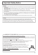
Important Safety Notice WARNING 1) To prevent damage which may result in fire or shock hazard, do not expose this appliance to dripping or splashing. Do not place containers with water (flower vase, cups, cosmetics, etc.) above the set. (including on shelves above, etc.) No naked flame sources, such as lighted candles, should be placed on / above the set. 2) To prevent electric shock, do not remove cover. No user serviceable parts inside. Refer servicing to qualified service personnel.
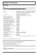
Safety Precautions WARNING Setup This Plasma Display is for use only with the following optional accessories. Use with any other type of optional accessories may cause instability which could result in the possibility of injury. (All of the following accessories are manufactured by Matsushita Electric Industrial Co., Ltd.) • Speakers ......................................................
Safety Precautions Ventilation should not be impleded by covering the ventilation openings with items such as newspapers, table cloths and curtains. For sufficient ventilation; If using the pedestal (optional accessory), leave a space of 10 cm or more at the top, left and right, and 7 cm or more at the rear, and also keep the space between the bottom of the display and the floor surface. If using some other setting-up method, follow the manual of it.
Safety Precautions CAUTION When using the Plasma Display Do not bring your hands, face or objects close to the ventilation holes of the Plasma Display. • Heated air comes out from the ventilation holes at the top of Plasma Display will be hot. Do not bring your hands or face, or objects which cannot withstand heat, close to this port, otherwise burns or deformation could result. Be sure to disconnect all cables before moving the Plasma Display.
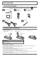
Accessories Accessories Supply Check that you have the accessories and items shown Operating Instruction book Remote Control Transmitter N2QAYB000178 Batteries for the Remote Control Transmitter (2 × R6 (UM3) Size) Power supply cord Fixing band × 1 Remote Control Batteries Requires two R6 batteries. 1. Pull and hold the hook, then open the battery cover. 2. Insert batteries - note correct polarity ( + and -). 3. Replace the cover.
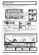
Connections When connecting the speakers, be sure to use only the optional accessory speakers. Refer to the speaker’s Installation Manual for details on speaker installation. (Example: TH-50PH11EK) Speakers (Optional accessories) 1 2 Speaker terminal (L) AC cord connection (see page 12) Speaker terminal (R) 1 2 – AC cord fixing Unplug the AC cord Close 1 Push until the hook clicks. 1 Plug the AC cord into the display unit. Plug the AC cord until 2 it clicks.
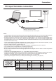
Connections PC Input Terminals connection (Female) COMPUTER AUDIO PC IN Conversion adapter (if necessary) RGB Mini D-sub 15p PC cable Audio (Male) Stereo plug Connect a cable which matches the audio output terminal on the computer. Notes: • Computer signals which can be input are those with a horizontal scanning frequency of 15 to 110 kHz and vertical scanning frequency of 48 to 120 Hz. (However, the image will not be displayed properly if the signals exceed 1,200 lines.
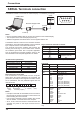
Connections SERIAL Terminals connection The SERIAL terminal is used when the Plasma Display is controlled by a computer. (Male) COMPUTER 1 2 6 3 7 4 8 5 9 SERIAL RS-232C Straight cable Pin layout for SERIAL Terminal (Female) D-sub 9p Notes: • Use the RS-232C straight cable to connect the computer to the Plasma Display. • The computer shown is for example purposes only. • Additional equipment and cables shown are not supplied with this set.
Connections AV connection This unit has a terminal board equivalent to BNC Dual Video Terminal Board (TY-FB9BD) as standard equipment. Example of input signal source R AUDIO S VIDEO VCR L B S VIDEO R AUDIO AV IN L VIDEO A SLOT1 SLOT2 SLOT3 PC IN CAMCORDER VCR R L S VIDEO R L OUT AUDIO AUDIO OUT OUT VIDEO OUT Note: Additional equipment, cables and adapter plugs shown are not supplied with this set.
Power On / Off Connecting the AC cord plug to the Plasma Display. Fix the AC cord plug securely to the Plasma Display with the clamper. (see page 8) Connecting the plug to the Wall Outlet Notes: • Main plug types vary between countries. The power plug shown at right may, therefore, not be the type fitted to your set. • When disconnecting the AC cord, be absolutely sure to disconnect the AC cord plug at the socket outlet first.
Power On / Off When first switching on the unit Following screen will be displayed when the unit is turned on for the first time. Select the items with the remote control. Unit buttons are invalid. OSD Language English (UK) OSD Language Deutsch 1 Français Select the language. Italiano Español 2 ENGLISH (US) Set. Select Set PRESENT TIME Setup 1 Select “DAY” or “PRESENT TIME”. 2 Setup “DAY” or “PRESENT TIME”. 1 Select “Set”.
Initial selections Selecting the input signal Select the input signals to be connected by installing the optional Terminal Boards. Press to select the input signal to be played back from the equipment which has been connected to the Plasma Display. Input signals will change as follows: INPUT1A INPUT1B INPUT2 INPUT3 PC SLOT1 is for dual input so that you can select INPUT1A or INPUT1B for INPUT1.
Basic Controls Main Unit Remote control sensor Volume Adjustment Volume Up “+” Down “–” When the menu screen is displayed: “+” : press to move the cursor up “–” : press to move the cursor down (see page 21) INPUT MENU Main Power On / Off Switch Power Indicator The Power Indicator will light. • Power-OFF .... Indicator not illuminated (The unit will still consume some power as long as the power cord is still inserted into the wall outlet.) • Standby ......... Red • Power-ON ...... Green • DPMS ..........
Basic Controls Remote Control Transmitter SURROUND button The surround setting switches on and off each time the SURROUND button is pressed. The benefits of surround sound are enormous. You can be completely enveloped in sound; just as if you were at a concert hall or cinema. Note: The surround settings are memorized separately for each Sound Mode (Normal, Dynamic, Clear). ACTION button Press to make selections. ASPECT button Press to adjust the aspect.
ASPECT Controls The Plasma Display will allow you to enjoy viewing the picture at its maximum size, including wide screen cinema format picture. Press repeatedly to move through the aspect options: For details about the aspect mode, please see “List of Aspect Modes” (page 44). For VIDEO (S VIDEO) signal input: 4:3 Zoom1 Zoom2 Zoom3 Just 14:9 16:9 Panasonic Auto Note: When selecting an input slot that attaches BNC Dual Video Terminal Board (TY-FB9BD), Panasonic Auto cannot be selected.
MULTI PIP Press repeatedly. Each time pressing this button main picture and sub picture will be displayed as follows below. [Picture and Picture] Main picture Normal Viewing Press to swap main picture and sub picture. Sub picture [Picture out Picture] Main picture Sub picture A B A B B A B A Press to select the input mode. Under main Picture and sub picture display, select the picture which you would like to change input modes.
MULTI PIP Advanced PIP 1 Set "Advanced PIP" to "On" in Options menu. (see page 39) 2 Press repeatedly. Each time pressing this button main picture and sub picture will be displayed as follows. One screen Advanced PIP Sub screen 1 8 Notes: • To use • and , , Main screen 2 3 4 7 6 5 buttons for the screen operations, follow the procedures in the previous page. buttons are invalid during Advanced PIP operation.
Digital Zoom This displays an enlargement of the designated part of the displayed image. 1 Display the operation guide. Press to access Digital Zoom. The operation guide will be displayed. Exit 1 During Digital Zoom, only the following buttons can be operated. [Remote control] SURROUND button OFF TIMER button VOL button [Unit] INPUT MENU -/ VOL +/ ENTER/ MUTE button VOL button POSITION / ACTION button 2 Select the area of the image to be enlarged.
On-Screen Menu Displays Remote Control Unit 1 Display the menu screen. Press several times. MENU Each time the MENU button is pressed, the menu screen will switch. Normal Viewing Picture Sound Pos. /Size Setup Press to select. (Example: Picture menu) 2 Select the item. Picture Normalise Select. Select. 1/2 Press. Normal Normal Picture Mode Contrast Brightness Colour Hue Sharpness 25 0 0 0 5 (Example: Picture menu) 3 Set. Set. Set. Press. 4 Exit the menu. Press several times.
Adjusting Pos. /Size 1 Press to display the Pos. /Size menu. Press to select the menu to adjust. 2 During “Video (S Video)”, “Digital”, “SDI” and “HDMI” input signal. Pos. /Size Normalise Auto Setup 0 0 0 0 H-Pos H-Size V-Pos V-Size Press to adjust the menu. 3 Normal During “Component”, “RGB” and “PC” input signal. Pos. /Size Normalise Auto Setup 4 Normal H-Pos H-Size V-Pos V-Size Dot Clock Clock Phase Press to exit from adjust mode. 0 0 0 0 0 0 Notes: • Unadjustable items are grayed out.
Picture Adjustments 1 2 Press to display the Picture menu. Select to adjust each item. Press to select the menu to adjust. Select the desired level by looking at the picture behind the menu. Note: Menu that cannot be adjusted is grayout. Adjustable menu changes depending on signal, input and menu setting. Picture Normalise 1/2 Press “ ” or “ ” button to switch between modes.
Picture Adjustments Item Contrast Brightness Colour Hue Sharpness Effect Less Adjustments More Darker Brighter Less More Reddish Greenish Less More Selects the proper brightness and density for the room. Adjusts for easier viewing of dark pictures such as night scenes and black hair. Adjusts colour saturation. Adjusts for nice skin colour. Adjusts picture sharpness. Notes: • “Colour” and “Hue” settings cannot be adjusted for “RGB/PC” and “Digital” input signal.
Sound Adjustment 1 Normalise 2 Select to adjust each item. Press to select the menu to adjust. Select the desired level by listening to the sound. 3 1/2 Sound Press to display the Sound menu. Normal Sound Mode Bass Mid Treble Balance Surround Audio Out (PIP) Normal 0 0 0 0 Off Main Press to exit from adjust mode. Item Sound Mode Bass Mid Treble Balance Surround Details Normal: Emits the original sound. Dynamic: Accentuates sharp sound. Clear: Attenuates human voice. Adjusts low pitch sounds.
PRESENT TIME Setup / Set up TIMER The timer can switch the Plasma Display On or Off. Before attempting Timer Set, confirm the PRESENT TIME and adjust if necessary. Then set POWER ON Time / POWER OFF Time. 1 2 Setup Press to display the Setup menu. Press to select Set up TIMER or PRESENT TIME Setup. MULTI DISPLAY Setup Set up TIMER PRESENT TIME Setup Display orientation 2/2 Landscape Press to display the Set up TIMER screen or PRESENT TIME Setup screen.
Screensaver (For preventing image retention) Do not display a still picture, especially in 4:3 mode, for any length of time. If the display must remain on, a Screensaver should be used. 1 Press to display the Setup menu. Press to select Screensaver. 2 Press to display Screensaver screen.
Screensaver (For preventing image retention) Reduces screen image retention These functions prevent the occurrence of an “image retention” on the display when turned ON. Wobbling: Automatically shifts the display image (therefore unnoticeable to the eye) to prevent image retention of sharper contour of image. On1: Shifts the image every 30 seconds. On2: Shifts the image at a dot level pitch depending on screen-detection. Peak limit: Suppresses image contrast (peak brightness).
Reduces power consumption • Power save: When this function is turned On, luminous level of the Plasma Display is suppressed, so power consumption is reduced. • Standby save: When this function is turned On, power consumption of the microcomputer is reduced during power supply standby (see page 12, 15, 16), so standby power of the set is reduced. • Power management: When this function is set to On, it operates under the following conditions to turn the power on or off automatically.
Customizing the Input labels This function can change the label of the Input signal to be displayed. Select the input signal which you would like to change its label before customizing the Input labels. (see page 14, 16) Setup 1/2 Signal Screensaver Component/RGB-in select Press to select Input label. RGB PC Off Off Off Off English (UK) Input label Power save Standby save Power management Auto power off OSD Language Press to change the Input label.
Setup for MULTI DISPLAY By lining up Plasma Displays in groups, for example, as illustrated below, an enlarged picture may be displayed across all screens. For this mode of operation, each plasma display has to be set up with a Display number to determine its location. (Example) group of 4 (2 × 2) group of 9 (3 × 3) group of 16 (4 × 4) group of 25 (5 × 5) How to Setup MULTI DISPLAY 1 Press to display the Setup menu. Setup Press to select the MULTI DISPLAY Setup.
Setup for MULTI DISPLAY Item Details Select “Off” or “On”. The brightness depends on each display’s setting. Equalize the brightness of all the displays. Off On AI-Synchronization Note: If you set AI-synchronization to On, the following menus will be unavailable and these settings will be fixed to the initial values. Picture menu: Colour, Hue, Input level (Advanced settings) 4 Press twice to exit from Setup.
Setup for Input Signals Component / RGB-in select Select to match the signals from the source connected to the Component / RGB input terminals. Y, PB, PR signals “Component” RGB signals “RGB” 1 2 Press to display the Setup menu. Press to select the “Component / RGB-in select”. Press to select the desired input signal.
Setup for Input Signals Signal menu Note: “Signal” setup menu displays a different setting condition for each input signal. 1 2 Setup Press to display the Setup menu. Signal Screensaver Component/RGB-in select Press to select the “Signal”. Press to select the menu to adjust. Press to adjust the menu. 4 RGB PC Off Off Off Off English (UK) Input label Power save Standby save Power management Auto power off OSD Language Press to display the Signal menu.
Setup for Input Signals Colour system / Panasonic Auto Select Signal from the “Setup” menu during AV(S Video) input signal. (“Signal [AV]” menu is displayed.) Press to select the “Colour system” or “Panasonic Auto”. Press to select each functions.
Setup for Input Signals Noise reduction ( Sets the following three NR (Noise Reduction) functions together. P-NR, Mosquito NR, Block NR ) Noise reduction Off Press to select “Noise reduction”. Press to select “Off”, “Min” , “Mid” , “Max” , “Advanced”. Advanced NR Sets the three NR functions separately. 1 Press to select “Advanced”. Press to enter Advanced NR. 2 Press to select P-NR, Mosquito NR or Block NR. Press to select “Off”, “Min”, “Mid”, “Max”.
Setup for Input Signals Sync Select Signal from the “Setup” menu during RGB input signal. Press to select the “Sync”. [ RGB ] Signal Press to adjust. Sync Cinema reality XGA Mode Auto Off 1024 × 768 Setting RGB sync signal: Confirm that the input is set to RGB input (this setting is valid only for RGB input signal). Auto: The H and V sync or synchronized signal are automatically selected. If both input, it is selected the H and V sync.
Options Adjustments 1 Options Press to display the Setup menu. 2 Weekly Command Timer Press to select “OSD Language”. 3 Onscreen display Initial INPUT Initial VOL level Maximum VOL level INPUT lock Button lock Remocon User level Advanced PIP Press and hold until the Options menu is displayed. 4 Press to select your preferred menu. 5 1/3 Press to adjust the menu.
Options Adjustments Item Adjustments INPUT lock Off PC INPUT1 INPUT2 INPUT3 Locks the input switch operation. Notes: • Only the adjusted signal is displayed (see page 14). • Signal can be displayed when the Terminal board is installed. • Input switch can be used when this is set to “Off”. • In two screen display mode, if anything other than “Off” is set, the value will be fixed as the value input in the single screen display mode.
Options Adjustments Item Adjustments Studio W/B Off: Nullify all the settings adjusted. On: Sets the colour temperature for TV studio. Note: Valid only when the low is set as colour temperature on screen adjustment. Studio Gain Sharpens the contrast for a better view when a part of the image is too light to see. Off: Disables “Studio Gain”. On: Enables “Studio Gain”.
Options Adjustments Weekly Command Timer You can set 7-day timer programming by setting time and command. Note: Before setting Weekly Command Timer, set PRESENT TIME Setup. (see page 26) 1 Press to select Function. Options 1/3 Press to select “On”. Weekly Command Timer Note: • When Function is set to On, Set up TIMER (see page 26) is unavailable and Interval / Time Designation in Mode of Screensaver (see page 27) cannot be selected.
Options Adjustments 6 Press to select Command No. Press to select a command number. Command setting screen Weekly Command Timer Program 1 Command No Time Command 7 Press to select Time / Command. 02 10:30 IMS:SL1 Weekly Command Timer 1 Program Press to set each item. 02 Command No Time: Set the time to execute a command program. 10:30 Time IMS:SL1 Command Pressing “ ” or “ ” button once changes “Time” 1 minute. Pressing “ ” or “ ” button continuously changes “Time” by 15 minutes.
Troubleshooting Before you call for service, determine the symptoms and make a few simple checks as shown below. Symptoms Picture Sound Interference Noisy Sound Normal Picture No Sound No Picture No Sound No Picture Normal Sound No Colour Normal Sound No remote control operations can be performed. A cracking sound is sometimes heard from the unit. The top or bottom of the picture on the screen is cut off when I use the zoom function.
List of Aspect Modes Aspect mode All Aspect: Factory setting On All Aspect: Off 16:9 14:9 16:9 Just – The pictures with a 4:3 aspect ratio among the 16:9 aspect ratio signals are enlarged horizontally so that the picture distortion is minimized. The left and right edges of the pictures are cut off. The display of the areas around the left and right edges of the screen is slightly elongated.
VIDEO/PC input signals VIDEO input Signal name 1 2 3 4 5 NTSC PAL PAL60 SECAM Modified NTSC Horizontal frequency(kHz) 15.73 15.63 15.73 15.63 15.73 Vertical frequency(Hz) 59.94 50.00 59.94 50.00 59.94 Applicable input signals for Mini D-sub 15P (Component) / Mini D-sub 15P (RGB) (* Mark) Horizontal Vertical Dot clock Mini D-sub 15P Mini D-sub 15P Signal name frequency frequency frequency (Component) (RGB) (kHz) (Hz) (MHz) 1 525 (480) / 60i 15.73 59.94 13.5 2 525 (480) / 60p 31.47 59.94 27.
Command list of Weekly Command Timer No.
Specifications TH-42PH11EK/S Power Source Power Consumption Power on Stand-by condition Power off condition Plasma Display panel Screen size (No.of pixels) Operating condition Temperature Humidity Applicable signals Colour System Scanning format PC signals Connection terminals AV IN PC IN SERIAL SPEAKERS (6 Ω) Accessories Supplied Remote Control Transmitter Batteries Fixing band Dimensions (W × H × D) Mass (weight) main unit only with speakers TH-50PH11EK/S 220 - 240 V AC, 50/60 Hz 275 W Save off 1.
Information on Disposal for Users of Waste Electrical & Electronic Equipment (private households) This symbol on the products and/or accompanying documents means that used electrical and electronic products should not be mixed with general household waste. For proper treatment, recovery and recycling, please take these products to designated collection points, where they will be accepted on a free of charge basis.