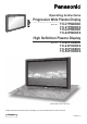
Operating Instructions Progressive Wide Plasma Display Model No. TH-37P WD8 TH-37PWD8EK TH-37PWD8ES TH-42PWD8EK TH-42PWD8ES High Definition Plasma Display Model No. TH-42PHD8EK TH-42PHD8ES TH-50PHD8EK TH-50PHD8ES TH-37PWD8 The illustration shown is an image. Please read these instructions before operating your set and retain them for future reference.
Dear Panasonic Customer Welcome to the Panasonic family of customers. We hope that you will have many years of enjoyment from your new Plasma Display. To obtain maximum benefit from your set, please read these Instructions before making any adjustments, and retain them for future reference. Retain your purchase receipt also, and note down the model number and serial number of your set in the space provided on the rear cover of these instructions. Visit our Panasonic Web Site http://www.panasonic.co.
Important Safety Notice WARNING 1) To prevent damage which may result in fire or shock hazard, do not expose this appliance to dripping or splashing. Do not place containers with water (flower vase, cups, cosmetics, etc.) above the set. (including on shelves above, etc.) No naked flame sources, such as lighted candles, should be placed on / above the set. 2) To prevent electric shock, do not remove cover. No user serviceable parts inside. Refer servicing to qualified service personnel.
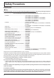
Safety Precautions WARNING Setup This Plasma Display is for use only with the following optional accessories. Use with any other type of optional accessories may cause instability which could result in the possibility of injury. (All of the following accessories are manufactured by Matsushita Electric Industrial Co., Ltd.) • Speakers ..............................................................
Safety Precautions When using the Plasma Display The Plasma Display is designed to operate on 220 - 240 V AC, 50/60 Hz. Do not cover the ventilation holes. • Doing so may cause the Plasma Display to overheat, which can cause fire or damage to the Plasma Display. Do not stick any foreign objects into the Plasma Display. • Do not insert any metal or flammable objects into the ventilations holes or drop them onto the Plasma Display, as doing so can cause fire or electric shock.
Safety Precautions CAUTION When using the Plasma Display Do not bring your hands, face or objects close to the ventilation holes of the Plasma Display. • Heated air comes out from the ventilation holes at the top of Plasma Display will be hot. Do not bring your hands or face, or objects which cannot withstand heat, close to this port, otherwise burns or deformation could result. Be sure to disconnect all cables before moving the Plasma Display.
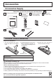
Accessories Accessories Supply Check that you have the accessories and items shown Operating Instruction book Remote Control Transmitter EUR7636070R or EUR7636090R Power supply cord Batteries for the Remote Control Transmitter (2 × R6 (UM3) Size) Pan European Guarantee Card Fixing bands × 2 Remote Control Batteries Requires two R6 batteries. 1. Turn the transmitter face down. Press and slide off the battery cover. 2. Install the batteries as shown in the battery compartment.
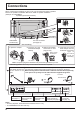
Connections When connecting the speakers, be sure to use only the optional accessory speakers. Refer to the speaker’s Installation Manual for details on speaker installation. (Example: TH-42PWD8EK) Speakers (Optional accessories) 1 2 1 SPEAKERS Terminals (L) SPEAKERS Terminals (R) AC cord connection (see page 12) 2 – AC cord fixing 1. Open the clamper. 2. Insert the AC cord and close the clamper securely. Clamper 3. Slide up the clamper and fix the AC cord plug securely. 4.
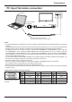
Connections PC Input Terminals connection COMPUTER AUDIO PC IN TH-42PWD8 Conversion adapter (if necessary) RGB Mini D-sub 15p PC cable Audio Stereo plug Connect a cable which matches the audio output terminal on the computer. Notes: • Due to space limitations, occasionally you may have trouble connecting Mini D-sub 15P cable with ferrite core to PC input Terminal.
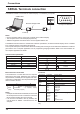
Connections SERIAL Terminals connection The SERIAL terminal is used when the Plasma Display is controlled by a computer. COMPUTER 6 1 SERIAL RS-232C Straight cable 7 2 8 3 9 4 5 Pin layout for RS-232C D-sub 9p Notes: • Use the RS-232C cable to connect the computer to the Plasma Display. • The computer shown is for example purposes only. • Additional equipment and cables shown are not supplied with this set.
Connections AV connection Example of input signal source S VIDEO VCR R AUDIO IN L VIDEO IN S VIDEO IN VIDEO OUT AV SLOT1 SLOT2 SLOT3 CAMCORDER PC IN MONITOR VIDEO IN VCR R L S VIDEO VIDEO OUT OUT AUDIO OUT Note: Additional equipment, cables and adapter plugs shown are not supplied with this set.
Power On / Off Connecting the AC cord plug to the Plasma Display. Fix the AC cord plug securely to the Plasma Display with the clamper. (see page 8) Connecting the plug to the Wall Outlet Note: Main plug types vary between countries. The power plug shown at right may, therefore, not be the type fitted to your set. TH-42PWD8 INPUT MENU -/ VOL +/ ENTER/ Power Indicator Press the Power switch on the Plasma Display to turn the set on: Power-On.
Initial selections Selecting the input signal Select the input signals to be connected by installing the optional Terminal Boards. Press to select the input signal to be played back from the equipment which has been connected to the Plasma Display. Input signals will change as follows: • TH-37PWD8EK/S INPUT1 INPUT2 PC IN • TH-42PWD8EK/S, TH-42PHD8EK/S, TH-50PHD8EK/S INPUT1 INPUT2 INPUT3 PC IN Notes: • Selecting is also possible by pressing the INPUT button on the unit.
Basic Controls Remote control sensor Volume Adjustment Volume Up “+” Down “–” When the menu screen is displayed: “+”: press to move the cursor up “–”: press to move the cursor down (see page 16) TH-42PWD8 INPUT MENU Main Power On / Off Switch Power Indicator The Power Indicator will light. • Power-OFF .... Indicator not illuminated (The unit will still consume some power as long as the power cord is still inserted into the wall outlet.) • Standby.......... Red • Power-ON ...... Green • DPMS ...........
Basic Controls Standby (ON / OFF) button The Plasma Display must first be plugged into the wall outlet and turned on at the power switch (see page 12). Press ON to turn the Plasma Display On, from Standby mode. Press OFF to turn the Plasma Display Off to Standby mode. POSITION buttons ACTION button Press to make selections. R button (see page 17) Press the R button to return to previous menu screen. Status button Press the “Status” button to display the current system status.
On-Screen Menu Displays To Picture adjust menu (see page 22) Picture Normalise The MENU button on the unit can also be pressed. 1 Press to select. 1/2 Normal Normal Picture Mode Contrast Brightness Colour Tint Sharpness INPUT 25 0 0 0 3 MENU -/ VOL +/ ENTER/ Each time the MENU button is pressed, the menu screen will switch. Picture 2/2 Normal Viewing Sound Picture Setup Pos.
On-Screen Menu Displays 2 Press to access [ from the unit ] each adjust screen. INPUT MENU -/ VOL +/ ENTER/ Press the R button to return to previous menu screen. Press to return to next menu screen.
ASPECT Controls The Plasma Display will allow you to enjoy viewing the picture at its maximum size, including wide screen cinema format picture. Press repeatedly to move through the aspect options: 4:3 Zoom Panasonic Auto [from the unit] INPUT MENU -/ VOL +/ 16 : 9 Just The aspect mode changes each time the ENTER button is pressed. ENTER/ [During MULTI PIP Operations] • Picture and Picture, Picture in Picture : • Others : 4:3 16 : 9 Aspect switching is not possible.
Adjusting Pos. / Size 1 Press to display the Pos. /Size menu. 2 Press to select H-Pos / H-Size / V-Pos / V-Size / Clock Phase. 3 Press to adjust Pos. / Size. During “AV(S Video)”, “Component” and “DVI” input signal. 4 Pos. /Size Press to exit from adjust mode.
MULTI PIP Press repeatedly. Each time pressing this button main picture and sub picture will be displayed as follows below. [Picture and Picture] Main picture Normal Viewing [Picture out Picture] Sub picture MULTI PIP Main picture MULTI PIP A B Main picture A B A B SWAP B A [Example] Press to select the input mode. Under main Picture and sub picture display, select the picture which you would like to change input modes.
Advanced PIP 1 Press to display the Setup menu. 2 Press to select “OSD Language”. 3 Press and hold until the Options menu is displayed. 4 Press to select Advanced PIP. 5 Press to adjust the menu. Off : Sets normal two screen display mode (see page 20). On : Sets Advanced PIP mode. Press to confirm. 6 Press to exit from Options menu.
Picture Adjustments 1 Press to display the Picture menu. 2 Select to adjust each item. Press to select the menu to adjust. Select the desired level by looking at the picture behind the menu. Picture Normalise 1/2 Press “ ” or “ ” button to switch between modes. Normal Normal Normal Picture Mode Contrast Brightness Colour Tint Sharpness Cinema 25 0 0 0 3 Normal For viewing in standard (evening lighting) environments. This menu selects the normal levels of Brightness and Contrast.
Picture Adjustments Item Contrast Brightness Colour Tint Sharpness Effect Less Notes: • “Colour” and “Tint” settings cannot be adjusted for “RGB/PC” and “DVI” input signal. • You can change the level of each function (Contrast, Brightness, Colour, Tint, Sharpness) for each Picture Mode. • The setting details for normal, dynamic and cinema respectively are memorized separately for each input terminal. • The “Tint” setting can be adjusted for NTSC signal only during “AV (S Video)” input signal.
Sound Adjustment 1 2 Press to display the Sound menu. Select to adjust each item. Press to select the menu to adjust. Select the desired level by listening to the sound. Bass Adjusts low pitch sounds Sound Normalise Mid Adjusts normal sounds Treble Adjusts high pitch sounds Balance Adjusts left and right volumes Sound Mode Bass Mid Treble Balance Surround Audio Out (PIP) Surround Select On or Off Emits the original sound. Normal Normal Main Sub Musical note Normal Accentuates sharp sound.
Digital Zoom This displays an enlargement of the designated part of the displayed image. 1 Display the “Operation Guide”. Exit Press to access Digital Zoom. The “Operation Guide” will be displayed. 1 During Digital Zoom, only the following buttons can be operated. [Remote control] [Unit] INPUT MENU -/ VOL +/ ENTER/ VOL button VOL button MUTE button SURROUND button OFF TIMER button 2 Select the area of the image to be enlarged. Press on the enlargement location to select.
PRESENT TIME Setup / Set up TIMER The timer can switch the Plasma Display On or Off. Before attempting Timer Set, confirm the PRESENT TIME and adjust if necessary. Then set POWER ON Time / POWER OFF Time. 1 Press to display the Setup menu. 2 Press to select Set up TIMER or PRESENT TIME Setup. Setup 1/2 Signal Component/RGB-in select Press to display the Set up TIMER screen or PRESENT TIME Setup screen.
PRESENT TIME Setup / Set up TIMER Set up TIMER Display the Set up TIMER screen. 1 Press to select POWER ON Time / POWER OFF Time. Set up TIMER PRESENT TIME 99:99 Off POWER ON Function Press to setup 0:00 POWER ON Time POWER ON Time / POWER OFF Time. Off POWER OFF Function button: Forward POWER OFF Time 0:00 button: Back Notes: • Pressing “ ” or “ ” button once changes POWER ON Time / POWER OFF Time 1minute. • Pressing “ ” or “ ” button continuously changes POWER ON Time / POWER OFF Time by 15 minutes.
Screensaver (For preventing after-images) Do not display a still picture, especially in 4:3 mode, for any length of time. If the display must remain on, a Screensaver should be used. 1 Press to display the Setup menu. 2 Press to select Screensaver. Setup 2/2 Screensaver MULTI DISPLAY Setup Set up TIMER PRESENT TIME Setup Press to display Screensaver screen. 3 Reversal / Scroll selection Screensaver PRESENT TIME Press to select Function. Press to select the desired function.
Screensaver (For preventing after-images) Setup of Screensaver Time After selecting Time Designation or Interval, the relevant Time Setup will become available for selection and the Operating Time may be set. (Time cannot be set when “Mode” is “On” or “Off”.
Screensaver (For preventing after-images) Side Panel Adjustment Do not display a picture in 4:3 mode for an extended period, as this can cause an after-image to remain on the side panels either side of the display field. To reduce the risk of such an after-image, illuminate the side panels. side panel 4:3 Screen Display after-images This function may be applicable to the non-picture area. Non picture area A Picture out Picture B Picture and Picture Display the Screensaver screen.
Reduces power consumption • Power save: When this function is turned On, luminous level of the Plasma Display is suppressed, so power consumption is reduced. • Standby save: When this fun ction is turned On, power consumption of the microcomputer is reduced during power supply standby (see page 12, 14-15), so standby power of the set is reduced. • Power management: The unit power supply is turned On or Off depending on whether or not there is a signal during PC input mode.
Setup for MULTI DISPLAY By lining up Plasma Displays in groups of 4, 9 or 16 as illustrated below, an enlarged picture may be displayed across all screens. For this mode of operation, each plasma display has to be set up with a Display number to determine its location. group of 4 (2 × 2 (F)) group of 9 (3 × 3 (F)) group of 16 (4 × 4 (F)) Two options are selectable for MULTI DISPLAY (See next page). How to Setup MULTI DISPLAY 1 2 Press to display the Setup menu.
Setup for MULTI DISPLAY How to set the display location number for each Plasma Display 4 Press to select Ratio (2nd step). MULTI DISPLAY Setup MULTI DISPLAY Setup Ratio Location Press to select “2 × 2”, “2 × 2 F”, “3 × 3”, “3 × 3F”, “4 × 4”, “4 × 4F”. 5 Press to select Location. Off 2×2 A1 MULTI DISPLAY Setup Press to select the required arrangement number.
Setup for MULTI DISPLAY ID Remote Control Function You can set the remote control ID when you want to use this remote control on one of several different TVs. 1 Switch to 2 Press the button on the remote control. 3 Press one of - , for the tens digit setting. 4 Press one of - , for the units digit setting. on the right side. Notes: • The numbers in 2, 3 and 4 should be set up quickly. • Adjustable ID number range is 0 - 99.
Setup for Input Signals Component / RGB-in select Select to match the signals from the source connected to the Component / RGB input terminals. Y, PB, PR signals “Component” R, G, B, HD, VD signals “RGB” 1 2 Press to display the Setup menu. Press to select the “Component / RGB-in select”. Press to select the desired input signal. Component RGB 3 Setup Press to exit from adjust mode. Note: Selection may not be possible, depending on which optional board is installed.
Setup for Input Signals Colour system / Panasonic Auto Select Signal from the “Setup” menu during AV(S Video) input signal. (“Signal [AV]” menu is displayed.) Setup 1/2 Signal Component/RGB-in select Press to select the “Colour system” or “Panasonic Auto”. RGB PC Off Off Off Off English (UK) Input label Power save Standby save Power management Auto power off OSD Language Press to select each functions.
Setup for Input Signals Sync Select Signal from the “Setup” menu during RGB input signal. 1 Press to adjust. Setup 1/2 Signal Component/RGB-in select Input label Power save Standby save Power management Auto power off OSD Language 2 RGB PC Off Off Off Off English (UK) Press ACTION ( ) button Press to exit from adjust mode. [ RGB ] Signal Sync Cinema reality P-NR Auto Off Off H-Freq. 33.8 kHz V-Freq. Hz 60.
Options Adjustments 1 Press to display the Setup menu. 2 Press to select “OSD Language”. 3 Press and hold until the Options menu is displayed. 4 Press to select your preferred menu. 5 Press to adjust the menu. Press or button to switch between modes. Off MENU&ENTER On Off All the buttons at the bottom of the main unit can be used. MENU & ENTER Locks and buttons on bottom face of main unit. On Locks all the button on bottom face of main unit. MENU Press to confirm.
Options Adjustments Options Off-timer function Onscreen display Initial INPUT Initial VOL level Maximum VOL level INPUT lock Studio W/B Advanced PIP Display size 1/2 Enable On Off Off 0 Off 0 Off Off Off Off Press or button to switch between modes. Off PC INPUT1 INPUT2 INPUT3 Locks the input switch operation. Notes: • Only the adjusted signal is displayed. (see page 13). • Signal can be displayed when the Terminal board is installed. • Input switch can be used when this is set to “Off”.
Options Adjustments 1/2 Options Off-timer function Onscreen display Initial INPUT Initial VOL level Maximum VOL level INPUT lock Studio W/B Advanced PIP Display size Enable On Off Off 0 Off 0 Off Off Off Off 2/2 Options Button lock Remocon User level ID select Remote ID Serial ID Slot power V. lnstallation Rotate Off Off Press or button to switch between modes. Off On Off Sets normal two screen display mode. (see page 20) On Sets Advanced PIP mode (see page 21).
Shipping condition This function allows you to reset the unit to the factory setting. 1 Press to display the Setup menu. 2 Press to select “OSD Language”. 3 Press and hold till the SHIPPING menu is displayed. Setup 1/2 Signal Component/RGB-in select 4 Press to select “YES”. Input label Power save Standby save Power management Auto power off OSD Language SHIPPING RGB PC Off Off Off Off English (UK) YES Press to confirm. [from the unit] 1 Press the MENU button till the Setup menu is displayed.
Troubleshooting Before you call for service, determine the symptoms and make a few simple checks as shown below. Symptoms Picture Sound Interference Noisy Sound Normal Picture No Sound No Picture No Sound No Picture Normal Sound No Colour Normal Sound No remote control operations can be performed. A cracking sound is sometimes heard from the unit. The top or bottom of the picture on the screen is cut off when I use the zoom function.
VIDEO/COMPONENT/RGB/PC input signals VIDEO input Signal name 1 2 3 4 5 NTSC PAL PAL60 SECAM Modified NTSC Horizontal frequency(kHz) 15.73 15.63 15.73 15.63 15.73 Vertical frequency(Hz) 59.94 50.00 59.94 50.00 59.94 Applicable input signals for Component / Mini D-sub 15P (Component) / RGB / Mini D-sub 15P (RGB) (∗ Mark) Component / RGB / Horizontal Vertical Signal name Mini D-sub 15P Mini D-sub 15P frequency (kHz) frequency (Hz) (Component) (RGB) ∗ ∗ 1 525 (480) / 60i 15.73 59.94 ∗ 2 525 (480) / 60p 31.
Specifications TH-37PWD8EK/S Power Source Power Consumption Normal use Stand-by condition Power off condition Plasma Display panel Contrast Ratio Screen size (No.
Specifications TH-42PHD8EK/S Power Source Power Consumption Normal use Stand-by condition Power off condition Plasma Display panel Contrast Ratio Screen size (No.
Information on Disposal for Users of Waste Electrical & Electronic Equipment (private households) This symbol on the products and/or accompanying documents means that used electrical and electronic products should not be mixed with general household waste. For proper treatment, recovery and recycling, please take these products to designated collection points, where they will be accepted on a free of charge basis.