
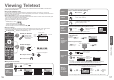
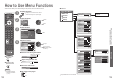
Operating Guide

8
9
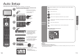
Quick Start Guide
VIDEO
RGB
AUDIO
AUDIO
VIDEO
S VIDEO
AV2
COMPONENT
VIDEO
RGB
AV1
PC
AUDIO
IN
L
R
Y
P
B
P
R
LR
RF IN
RF OUT
VIDEO
RGB
AUDIO
AUDIO
VIDEO
S VIDEO
AV2
COMPONENT
VIDEO
RGB
AV1
PC
AUDIO
IN
L
R
Y
P
B
P
R
LR
VIDEO
RGB
AUDIO
AUDIO
VIDEO
S VIDEO
AV2
COMPONENT
VIDEO
RGB
AV1
PC
AUDIO
IN
L
R
Y
P
B
P
R
LR
RF OUT
RF IN
RF OUT
RF IN
RF IN
•
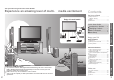
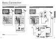
Basic Connection
Basic Connection
External equipment and cables shown are not supplied with this TV.
Please ensure that the unit is disconnected from the mains socket before attaching or disconnecting any leads.
When disconnecting the mains lead, be absolutely sure to disconnect the mains plug at the socket outlet fi rst.
Example 1
Connecting aerial
Example 2
Connecting DVD Recorder / VCR
TV only TV, DVD Recorder or VCR
Note
•
Connect to AV1 / 2 for a DVD Recorder / VCR supporting Q-Link (p. 32).
Example 3
Connecting DVD Recorder / VCR and Set top box
TV, DVD Recorder / VCR and Set top box
DVD Recorder
or VCR
SCART cable
(fully wired)
RF cable
Aerial
Mains lead (supplied)
Rear of the TV
Set top box
AC 220-240 V
50 / 60 Hz
RF cable
RF cable
SCART cable
(fully wired)
SCART cable
(fully wired)
RF cable
Clamper
•
To unfasten
Mains lead (supplied)
Mains lead (supplied)
SCART cable
(fully wired)
DVD Recorder or VCR
RF
cable
Aerial AerialRear of the TV Rear of the TV
RF cable
RF cable
AC 220-240 V
50 / 60 Hz
AC 220-240 V
50 / 60 Hz