Model No. TH-85PB1U Operating Instructions Display Operations Interactive Plasma Display English Before connecting, operating or adjusting this product, please read these instructions completely. Please keep this manual for future reference.
CAUTION RISK OF ELECTRIC SHOCK DO NOT OPEN WARNING: To reduce the risk of electric shock, do not remove cover or back. No user-serviceable parts inside. Refer servicing to quali ed service personnel. The lightning flash with arrowhead within a triangle is intended to tell the user that parts inside the product are a risk of electric shock to persons. The exclamation point within a triangle is intended to tell the user that important operating and servicing instructions are in the papers with the appliance.
Important Safety Instructions 1) Read these instructions. 2) Keep these instructions. 3) Heed all warnings. 4) Follow all instructions. 5) Do not use this apparatus near water. 6) Clean only with dry cloth. 7) Do not block any ventilation openings. Install in accordance with the manufacturer’s instructions. 8) Do not install near any heat sources such as radiators, heat registers, stoves, or other apparatus (including ampli ers) that produce heat.
Dear Panasonic Customer Welcome to the Panasonic family of customers. We hope that you will have many years of enjoyment from your new Plasma Display. To obtain maximum benefit from your set, please read these Instructions before making any adjustments, and retain them for future reference. Retain your purchase receipt as well, and record the model number and serial number of your set in the space provided on the rear cover of these instructions. Visit our Panasonic Web Site http://panasonic.
FCC STATEMENT This equipment has been tested and found to comply with the limits for a Class B digital device, pursuant to Part 15 of the FCC Rules. These limits are designed to provide reasonable protection against harmful interference in a residential installation. This equipment generates, uses and can radiate radio frequency energy and, if not installed and used in accordance with the instructions, may cause harmful interference to radio communications.
Safety Precautions CAUTION This Plasma Display is for use only with the following optional accessories. Use with any other type of optional accessories may cause instability which could result in the possibility of injury. (All of the following accessories are manufactured by Panasonic Corporation.) • Pedestal .................................................................... TY-ST85P12 • Mobile Stand for Display ........................................... TY-ST85PB1 • Floor stand ........................
Safety Precautions WARNING Setup Do not place the Plasma Display on sloped or unstable surfaces, and ensure that the Plasma Display does not hang over the edge of the base. • The Plasma Display may fall off or tip over. Do not place any objects on top of the Plasma Display. • If water spills onto the Plasma Display or foreign objects get inside it, a short-circuit may occur which could result in re or electric shock.
Accessories Accessories Supplied Check that you have the Accessories and items shown Operating Instruction book CD-ROM × 1 Remote Control Transmitter N2QAYB000691 • Operating Instructions Display Operations Network Operations • Software license statements GNU GENERAL PUBLIC LICENSE GNU LESSER GENERAL PUBLIC LICENSE Fixing band × 2 TMME203 Clamper × 1 TMM15412-2 Use the clamper when connecting a LAN cable.
Accessories Remote Control Batteries Requires two AA batteries. 1. Pull and hold the hook, then open the battery cover. 2. Insert batteries - note correct polarity (+ and -). 3. Replace the cover. “AA” size + + - Helpful Hint: For frequent remote control users, replace old batteries with Alkaline batteries for longer life. Precaution on battery use Incorrect installation can cause battery leakage and corrosion that will damage the remote control transmitter.
Connections Cable xing – How to Unfasten the AC cord Loosen the xing band securing the AC cord. To loosen: Push the catch Pull – Cable xing bands Secure any excess cables with bands as required. Note: Two xing bands are supplied with this unit. In case of securing cables at three positions, please purchase it separately. Pass the attached cable xing band through the clip as shown in the gure.
Connections Video equipment connection SLOT: Terminal board (optional accessories) insert slot (see page 6) Note: The lower side slot is for terminal board with 2-slot width. The terminal board with 1-slot width does not function when installed in the lower side slot. AV IN (VIDEO): Composite Video Input Terminal (see page 12) COMPONENT/RGB IN: Component/RGB Video Input Terminal (see page 12) SERIAL: Control the Plasma Display by connecting to PC.
Connections AUDIO OUT Terminals connection audio equipment Stereophonic sound code line-in VIDEO and COMPONENT / RGB IN connection Note: Additional equipment, cables and adapter plugs shown are not supplied with this set. VIDEO OUT L RCA-BNC Adapter plug R AUDIO L-R: Shared with VIDEO and COMPONENT/RGB IN AUDIO OUT VCR Notes: • Change the “COMPONENT/RGB-IN SELECT” setting in the “SETUP” menu to “COMPONENT” (when COMPONENT signal connection) or “RGB” (when RGB signal connection).
Connections HDMI connection [Pin assignments and signal names] Pin No. 1 2 3 4 5 6 7 8 9 10 Signal Name Pin No. 11 T.M.D.S Data2+ T.M.D.S Data2 Shield T.M.D.S Data2T.M.D.S Data1+ T.M.D.S Data1 Shield T.M.D.S Data1T.M.D.S Data0+ T.M.D.S Data0 Shield T.M.D.S Data0T.M.D.S Clock+ Signal Name T.M.D.S Clock Shield 12 T.M.D.S Clock- 13 CEC 14 Reserved (N.C.
Connections PC Input Terminals connection Shared with DVI-D IN. COMPUTER Conversion adapter (if necessary) (Female) (Male) Mini D-sub 15p Stereo mini plug (M3) Connect a cable which matches the audio output terminal on the computer. Notes: • With regard to the typical PC input signals that are described in the applicable input signals list (see page 62), adjustment values such as for the standard picture positions and sizes have already been stored in this unit.
Connections SERIAL Terminals connection The SERIAL terminal is used when the Plasma Display is controlled by a computer. Note: To use serial control for this unit, make sure to set the “CONTROL I/F SELECT” in the “NETWORK SETUP” menu to “RS-232C”. (refer to “Operating Instructions, Network Operations”) COMPUTER (Male) 9 5 RS-232C Straight cable 8 4 7 3 6 2 1 Pin layout for SERIAL Terminal (Female) D-sub 9p Notes: • Use the RS-232C straight cable to connect the computer to the Plasma Display.
Power ON / OFF Connecting the plug to the Wall Outlet. Press the Power switch on the Plasma Display to turn the set on: Power-On. Power Indicator: Green Right side surface [Starting up the network] It takes some time for the network to start up just after the power is turned on. During that time, “NETWORK SETUP” in the “SETUP” menu is grayed out and cannot be set. Main Power On / Off Switch Remote Control Sensor Press the Power Indicator button on the remote control to turn the Plasma Display off.
Power ON / OFF When rst switching on the unit Following screen will be displayed when the unit is turned on for the rst time. Select the items with the remote control. Unit buttons are invalid.
Selecting the input signal Press to select the input signal to be played back from the equipment which has been connected to the Plasma Display. Input signals will change as follows: PC NETWORK VIDEO COMPONENT* HDMI DVI PC: PC input terminal in PC IN. NETWORK: Network input terminal in LAN or WIRELESS MODULE. VIDEO: Video input terminal in AV IN (VIDEO). COMPONENT*: Component or RGB input terminal in COMPONENT/RGB IN. HDMI: HDMI input terminal in AV IN (HDMI). DVI: DVI input terminal in DVI-D IN.
Basic Controls Main Unit Right side surface ENTER/ + / VOL - Brightness Sensor Detects the brightness in the viewing environment Remote control sensor Power Indicator The Power Indicator will light. • Power-OFF .... Indicator not illuminated (The unit will still consume some power as long as the power cord is still inserted into the wall outlet.) • Standby ......... Red Orange (When “Slot power” is set to “On”.
Basic Controls Remote Control Transmitter ACTION button Press to make selections. ASPECT button Press to adjust the aspect. (see page 21) Standby (ON / OFF) button The Plasma Display must rst be plugged into the wall outlet and turned on at the power switch (see page 16). Press this button to turn the Plasma Display On, from Standby mode. Press it again to turn the Plasma Display Off to Standby mode. POS.
ASPECT Controls The Plasma Display will allow you to enjoy viewing the picture at its maximum size, including wide screen cinema format picture. Note: Be aware that if you put the display in a public place for commercial purposes or a public showing and then use the aspect mode select function to shrink or expand the picture, you may be violating the copyright under copyright law.
Digital Zoom This displays an enlargement of the designated part of the displayed image. 1 Display the operation guide. EXIT Press to access Digital Zoom. The operation guide will be displayed. 1 During Digital Zoom, only the following buttons can be operated. [Remote control] OFF TIMER button [Unit] ENTER/ + / VOL VOL button - VOL button / MUTE button MENU POSITION / ACTION button 2 INPUT Select the area of the image to be enlarged. Press on the enlargement location to select.
On-Screen Menu Displays Remote Control Unit 1 Display the menu screen. MENU Press to select. (Example: PICTURE menu) 2 Select the item. Each time the MENU button is pressed, the menu screen will switch. Normal Viewing PICTURE SETUP SOUND POS./SIZE Select. PICTURE Press several times. ENTER/ Press. NORMALIZE NORMAL STANDARD 25 0 0 0 5 NORMAL PICTURE MENU PICTURE BRIGHTNESS COLOR TINT SHARPNESS COLOR TEMP ADVANCED SETTINGS + / VOL - (Example: PICTURE menu) Select.
Adjusting POS./SIZE 1 2 Press to display the POS./SIZE menu. Press to select the menu to adjust. POS./SIZE NORMALIZE NORMAL AUTO SETUP 3 4 H-POS H-SIZE V-POS V-SIZE DOT CLOCK CLOCK PHASE CLAMP POSITION 1:1 PIXEL MODE Press to adjust the menu. Press to exit from adjust mode. 0 0 0 0 0 0 0 OFF Note: Unadjustable items are grayed out. Adjustable items differ depending on the input signal and the display mode. Notes: • Adjustment details are memorized separately for different input signal formats.
Adjusting POS./SIZE Notes: • If the dot clock frequency of an analog signal is 162 MHz or higher, “DOT CLOCK” and “CLOCK PHASE” cannot be automatically corrected. • When digital signal input, DOT CLOCK and CLOCK PHASE cannot be made. • AUTO SETUP may not work when a cropped or dark image is input. In such case, switch to a bright image with borders and other objects are clearly shown, and then try auto setup again. • Depending on the signal, out of alignment may occur after AUTO SETUP.
Adjusting POS./SIZE CLAMP POSITION (During Component/PC input signal) Adjusts the clamp position when black parts of the image have no detail due to underexposure or are tinged with green. Optimum value for Clamp Position adjustment When black parts have no detail due to underexposure (blackout) Value that causes least blackout is the optimum. When black parts are tinged with green Value that cancels the greenishness without causing blackout is the optimum.
PICTURE Adjustments 1 2 Press to display the PICTURE menu. Select to adjust each item. Press to select the menu to adjust. Select the desired level by looking at the picture behind the menu. Note: Menu that cannot be adjusted is grayout. Adjustable menu changes depending on signal, input and menu setting.
PICTURE Adjustments Item PICTURE BRIGHTNESS COLOR TINT SHARPNESS Effect Less Adjustments More Darker Brighter Less More Reddish Greenish Less More Adjusts the proper picture contrast. Adjusts for easier viewing of dark pictures such as night scenes and black hair. Adjusts color saturation. Adjusts for natural esh tones. Notes: • You can change the level of each function (PICTURE, BRIGHTNESS, COLOR, TINT, SHARPNESS) for each PICTURE MENU.
Picture Pro les Up to 8 combinations of picture adjustment values (in the PICTURE menu and ADVANCED SETTINGS) can be stored in the display memory as pro les and applied as needed, for a convenient way to enjoy your preferred picture settings.
Picture Pro les Saving pro les Follow these steps to save picture adjustment values as pro les. Note: When the settings are locked in “EXTENDED LIFE SETTINGS”, pro les cannot be saved. 1 Specify the picture quality in the PICTURE menu and ADVANCED SETTINGS. (see page 27, 28) 2 In the PICTURE menu, select “MEMORY SAVE”. MEMORY SAVE 1 select MEMORY LOAD MEMORY EDIT 3 5 2 access A N a n 0 ! _ Select a pro le name for saving the picture adjustment values. 1 select MEMORY SAVE 1. [ 2. [ 3. [ 4.
Picture Pro les Loading pro les Load pro les and apply the picture adjustment values to the display as follows. Notes: • Loaded pro les are stored in memory according to the selected input interface. (see page 18) • When the settings are locked in “EXTENDED LIFE SETTINGS”, pro les cannot be loaded. Select the pro le to load. In the PICTURE menu, select “MEMORY LOAD”. select 1 MEMORY SAVE 1 2 MEMORY LOAD MEMORY LOAD MEMORY EDIT 2 access 1. [ 2. [ 3. [ 4.
SOUND Adjustment 1 SOUND Press to display the SOUND menu. 1/2 NORMALIZE NORMAL 2 Select to adjust each item. Press to select the menu to adjust. Select the desired level by listening to the sound. 3 OUTPUT SELECT AUDIO MENU BASS MID TREBLE BALANCE SURROUND SPEAKERS STANDARD 0 0 0 0 OFF Press to exit from adjust mode. Item OUTPUT SELECT Details Select the audio output. SPEAKERS: Internal speakers AUDIO OUT: AUDIO OUT terminal output Notes: • If “AUDIO OUT” is selected, only “BALANCE” can be set.
SETUP menu 1 Press to display the SETUP menu. Press to select the menu to adjust. 2 Press to adjust the menu. 3 4 SETUP 1/2 TOUCH-PEN SETTINGS SIGNAL SCREENSAVER EXTENDED LIFE SETTINGS ECO MODE SETTINGS INPUT LABEL FUNCTION BUTTON SETTINGS COMPONENT/RGB-IN SELECT RGB NO ACTIVITY POWER OFF DISABLE 30 S MENU DISPLAY DURATION 5 OSD BRIGHTNESS OSD LANGUAGE ENGLISH (US) Press to exit from adjust mode. Press to return to the previous menu.
DAY/TIME SETUP / ON/OFF TIMER SETUP The timer can switch the Plasma Display ON or OFF. Before attempting Timer Set, con rm the TIME and adjust if necessary. Then set POWER ON TIME / POWER OFF TIME. 1 Press to display the SETUP menu. 2 Press to select ON/OFF TIMER SETUP or DAY/TIME SETUP. Press to display the ON/OFF TIMER SETUP screen or DAY/TIME SETUP screen.
TOUCH-PEN SETTINGS Set Touch Pen mode. Select “TOUCH-PEN SETTINGS” in “SETUP” menu and press button. TOUCH-PEN SETTINGS TOUCH-PEN MODE SLOT INPUT HDMI DVI PC NETWORK TOUCH ONLY OFF OFF OFF OFF OFF When a Terminal Board with dual input terminals is installed, “SLOT INPUT” is displayed as “SLOT INPUT A” and “SLOT INPUT B”. TOUCH-PEN MODE Select an appropriate setting for the function of the electronic pen used.
SCREENSAVER (For preventing image retention) Do not display a still picture, especially in 4:3 mode, for any length of time. If the display must remain on, a SCREENSAVER should be used. 1 2 Select “SCREENSAVER” in “SETUP” menu and press button. FUNCTION selection Press to select the FUNCTION. Press to select the desired function.
SCREENSAVER (For preventing image retention) Setup of SCREENSAVER Time After selecting TIME OF DAY, INTERVAL or STANDBY AFTER SCR SAVER, the relevant Time Setup will become available for selection and the Operating Time may be set. (Time cannot be set when “MODE” is “ON” or “OFF”.) Press to select START TIME / FINISH TIME (when TIME OF DAY is selected). Press to select SHOW DURATION / SAVER DURATION (when INTERVAL is selected).
Reduces screen image retention EXTENDED LIFE SETTINGS The following settings are setup to reduce image retention: Select “EXTENDED LIFE SETTINGS” in “SETUP” menu and press button.
Reduces screen image retention NANODRIFT SAVER Moves the display position of the screen slightly to reduce image retention on the display panel. LOW–HIGH: NANODRIFT SAVER operates. The display position of the screen moves at set time intervals. You can set the screen movement range. Some of the screen may appear to be missing as a result of this operation. If you change the value, a mask is displayed in the range where the picture is missing as a result of position movement.
Reduces screen image retention CUSTOM SETTINGS Set the individual “Image Retention Reduction” menu. 1 Select “CUSTOM SETTINGS”. EXTENDED LIFE SETTINGS EXPRESS SETTINGS CUSTOM SETTINGS RESET 1 select 2 access set each menu to the recommended setting: 2 To Select “RECOMMENDED SETTINGS”.
ECO MODE SETTINGS Select “ECO MODE SETTINGS” in “SETUP” menu and press button. ECO MODE SETTINGS ECO MODE CUSTOM OFF ON POWER SAVE STANDBY SAVE PC POWER MANAGEMENT DVI-D POWER MANAGEMENT NO SIGNAL POWER OFF 1 select 2 adjust OFF OFF DISABLE ECO MODE CUSTOM: The menu of power consumption reduction is individually set. ON: The following xed values are set to the menu of power consumption reduction. Individual setting is not available.
Customizing the Input labels This function can change the label of the Input signal to be displayed. (see page 18) Select “INPUT LABEL” in “SETUP” menu and press button.
FUNCTION BUTTON SETTINGS Set the functions that operates when is pressed. FUNCTION BUTTON SETTINGS Select “FUNCTION BUTTON SETTINGS” in “SETUP” menu and press FUNCTION BUTTON 1 TOUCH-PEN FUNCTION BUTTON 2 SCROLLING BAR FUNCTION BUTTON GUIDE ON button. Note: Factory settings are as follows. FUNCTION1 button: TOUCH-PEN FUNCTION2 button: SCROLLING BAR • FUNCTION BUTTON 1, FUNCTION BUTTON 2 The following functions are set to the FUNCTION button.
NO ACTIVITY POWER OFF DISABLE ENABLE When this function is set to “ENABLE”, the power is turned off (standby) automatically when there is no operation of the Plasma Display for 4 hours. Starting from 3 minutes before the turn off, the remaining time will be displayed. PRESS ANY KEY TO ABORT. NO ACTIVITY POWER OFF 3MIN When the power is turned off due to this function, a message “LAST TURN OFF DUE TO ’NO ACTIVITY POWER OFF’.” is displayed next time the power is turned on.
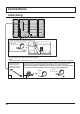
SETUP for MULTI DISPLAY By lining up Plasma Displays in groups, for example, as illustrated below, an enlarged picture may be displayed across all screens. For this mode of operation, each plasma display has to be set up with a Display number to determine its location. Note: During Touch Pen mode, “MULTI DISPLAY SETUP” becomes “OFF” and this function cannot be used.
SETUP for MULTI DISPLAY Item Details Reduces the peak of brightness for each display to enable as uniform display as possible. The brightness difference is The brightness depends on each Select “OFF” or “ON”. minimized. display’s setting. VIDEO WALL UNIFORMITY OFF ON Note: If you set VIDEO WALL UNIFORMITY to ON, the following menus will be unavailable and these settings will be xed to the initial values.
SETUP for PORTRAIT Divide an input image into 3 parts, and display one of them to a plasma display which is set vertically. The image will be enlarged 3 times and rotated 90-degree. (Example) Notes: • During Touch Pen mode, “PORTRAIT SETUP” becomes “OFF” and this function cannot be used. • When using the PORTRAIT function with displays set vertically, “DISPLAY ORIENTATION” in SETUP menu has to be set to “PORTRAIT” (see page 44).
SETUP for PORTRAIT 4 VIEWING AREA / LOCATION VIEWING AREA: Set a mode of image division for PORTRAIT function. LOCATION: Set a location of image to be displayed for PORTRAIT function. Press to select VIEWING AREA or LOCATION. Press to select each function. PORTRAIT SETUP PORTRAIT SETUP SEAM HIDES VIDEO VIEWING AREA LOCATION VIDEO WALL UNIFORMITY Notes: • For HD signal videos, the “VIEWING AREA” is set at “16:9”, and cannot be changed.
SETUP for Input Signals COMPONENT / RGB IN SELECT COMPONENT RGB Select to match the signals from the source connected to the Component / RGB or PC input terminals. “COMPONENT” Y, PB, PR signals “RGB” RGB signals Note: Make setting of the selected input terminal (COMPONENT/RGB IN or PC IN). YUV / RGB IN SELECT YUV RGB Select to match the signals from the source connected to the DVI input terminals.
SETUP for Input Signals SIGNAL menu Note: “SIGNAL” setup menu displays a different setting condition for each input signal. Select “SIGNAL” in “SETUP” menu and press For VIDEO (S VIDEO) For RGB [ VIDEO ] SIGNAL 3D Y/C FILTER (NTSC) COLOR SYSTEM 3 : 2 PULLDOWN NOISE REDUCTION [ RGB ] SIGNAL SYNC 3 : 2 PULLDOWN XGA MODE NOISE REDUCTION ON AUTO OFF OFF AUTO OFF AUTO OFF H-FREQ. 63.98 kHz V-FREQ. 60.02 Hz SIGNAL FORMAT 1280×1024/60i For COMPONENT [ COMPONENT ] SIGNAL button.
SETUP for Input Signals • SYNC This function operates only during input from PC IN terminal. Setting RGB sync signal Con rm that the input is set to RGB input (this setting is valid only for RGB input signal). AUTO: The H and V sync or synchronized signal is automatically selected. If both input, it is selected the H and V sync. ON G: Uses a synchronized signal on the Video G signal, which is input from the G connector.
SETUP for Input Signals • NOISE REDUCTION Sets the following three NR (Noise Reduction) functions together. VIDEO NR, MOSQUITO NR, BLOCK NR Press to select “NOISE REDUCTION”. ( ) NOISE REDUCTION OFF ( ) NOISE REDUCTION ADVANCED Press to select “OFF”, “MIN”, “MID”, “MAX”, “ADVANCED”. Advanced NR Sets the three NR functions separately. 1 Press to select “ADVANCED”. ADVANCED NR Press to enter ADVANCED NR. 2 Press to select VIDEO NR, MOSQUITO NR or BLOCK NR.
Options Adjustments Options 1 Press to display the SETUP menu. Weekly Command Timer Audio input select Input Search Press to select “OSD LANGUAGE”. 2 Onscreen display Initial input Initial VOL level Maximum VOL level Input lock Button lock Remocon User level Press for more than 3 seconds. Press to select “Options”. 3 Options Shipping Press to display the Options menu. Press to select your preferred menu. 4 Press to adjust the menu.
Options Adjustments Item Adjustments Input lock Locks the input switch operation. SLOT INPUT*1 VIDEO COMPONENT*2 HDMI DVI PC NETWORK Off *1 “SLOT INPUT” is displayed when an optional Terminal Board is installed. When a Terminal Board with dual input terminals is installed, “SLOT INPUT A” and “SLOT INPUT B” are displayed. *2 “COMPONENT” may be displayed as “RGB” depending on the setting of “COMPONENT/RGB-IN SELECT”. (see page 49) Notes: • Only the adjusted signal is displayed (see page 18).
Options Adjustments Item Adjustments Studio W/B Off: Nullify all the settings adjusted. On: Sets the color temperature for TV studio. Note: Valid only when the “WARM” is set as “COLOR TEMP” in PICTURE menu. Studio Gain Sharpens the contrast for a better view when a part of the image is too light to see. Off: Disables “Studio Gain”. On: Enables “Studio Gain”.
Options Adjustments Normalization When both main unit buttons and remote control are disabled due to the “Button lock”, “Remocon User level” or “Remote ID” adjustments, set all the values “Off” so that all the buttons are enabled again. button on main unit together with button on the remote control and hold for more than 5 seconds. The Press the “Shipping” menu is displayed and the lock is released when it disappears. Weekly Command Timer You can set 7-day timer programming by setting time and command.
Options Adjustments Press to select a command number. 5 Press to show the previous / next command pages (1-8) of the selected program. Press to show the command setting screen.
Options Adjustments Audio input select Set up the sound when an image input is selected. Options 1/3 Weekly Command Timer Audio input select Input Search Onscreen display On Press ACTION ( ) button Audio input select Press to select image input. Press to select audio input.
Options Adjustments Input Search When a signal is not detected, another input with a signal is automatically selected. Options 1/3 Weekly Command Timer Audio input select Input Search Press ACTION ( ) button 1 select Input Search 2 adjust Input Search Primary Input Secondary Input Off Input Search Off: When there is no signal, the input is not switched automatically. All Inputs: Searches all inputs and switches to an input with a signal. Input search is executed in the following order.
Troubleshooting Before you call for service, determine the symptoms and make a few simple checks as shown below. Symptoms Picture Sound Checks Electrical Appliances Cars / Motorcycles Fluorescent light Volume (Check whether the mute function has been activated on the remote control.) Check if speakers are connected properly. Not plugged into AC outlet Not switched on PICTURE and BRIGHTNESS/Volume setting (Check by pressing the power switch or stand-by button on the remote control.
List of Aspect Modes Aspect mode All Aspect: Factory setting On All Aspect: Off 16:9 14:9 FULL JUST JUST Pictures with a 4:3 aspect ratio are enlarged horizontally so that the picture distortion is minimized. The left and right edges of the pictures are cut off. The display of the areas around the left and right edges of the screen is slightly elongated. 4:3 4:3 (1) 4:3 H-FILL Zoom ZOOM Zoom1 Zoom2 Zoom3 The display of the pictures lls the screen.
Applicable Input Signals *Mark: Applicable input signal Horizontal frequency (kHz) 525 (480) / 60i 15.73 525 (480) / 60p 31.47 625 (575) / 50i 15.63 625 (576) / 50i 15.63 625 (575) / 50p 31.25 625 (576) / 50p 31.25 750 (720) / 60p 45.00 750 (720) / 50p 37.50 1,125 (1,080) / 60p 67.50 1,125 (1,080) / 60i 33.75 1,125 (1,080) / 50p 56.26 1,125 (1,080) / 50i 28.13 1,125 (1,080) / 24sF 27.00 1,125 (1,080) / 30p 33.75 1,125 (1,080) / 25p 28.13 1,125 (1,080) / 24p 27.00 1,250 (1,080) / 50i 31.25 27.
Applicable Input Signals Video input (VIDEO) Signal name 1 2 3 4 5 NTSC PAL PAL60 SECAM Modi ed NTSC Horizontal frequency(kHz) 15.73 15.63 15.73 15.63 15.73 Vertical frequency(Hz) 59.94 50.00 59.94 50.00 59.94 Shipping condition This function allows you to reset the unit to the factory setting. 1 2 Press to display the SETUP menu. Press to select “OSD LANGUAGE”. Press for more than 3 seconds. 3 Press to select “Shipping”. Press to display the Shipping menu. 4 Press to select “YES”.
Command list of Weekly Command Timer No.
Speci cations Power Source Power Consumption Rated Power Consumption Stand-by condition Power off condition Plasma Display panel Screen size (No.of pixels) Operating condition Temperature Humidity Applicable signals Color System Scanning format PC signals Connection terminals VIDEO AV IN AUDIO L-R HDMI COMPONENT/RGB IN Y/G PB/CB/B PR/CR/R AUDIO L-R DVI-D IN AUDIO PC IN AUDIO SERIAL WIRELESS MODULE LAN AUDIO L-R OUT Sound Speakers Audio Output TH-85PB1U 120 V AC, 50/60 Hz 1,170 W 0.4 W 0.
This product incorporates the following software: (1) the software developed independently by or for Panasonic Corporation, (2) the software owned by third party and licensed to Panasonic Corporation, (3) the software licensed under the GNU General Public License, Version 2.0 (GPL-2.0), (4) the software licensed under the GNU LESSER General Public License, Version 2.1 (LGPL-2.1) and/or, (5) open source software other than the software licensed under the GPL and/or LGPL.