Operating Manual HD Visual Communication Unit Model No. KX-VC500 Thank you for purchasing a Panasonic HD Visual Communication Unit. Please read this manual carefully before using this product and save this manual for future use. In this manual, the suffix of each model number (e.g., KX-VC500NA) is omitted unless necessary.
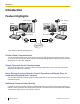
Introduction Introduction Feature Highlights Video camera Video camera Display Display Microphone Microphone DCE *1 DCE *1 Router Router Internet *1 DCE: Data Circuit-terminating Equipment Lifelike Visual Communication You can experience lifelike visual communication with smooth, high-quality video and clear stereo*2 sound. If using 2 or more microphones, stereo output can be enabled through system settings (only when Boundary Microphones are connected).
Introduction Selectable Video Source By connecting your computer or video camera to the KX-VC500, you can show your computer’s screen or video camera image to video conference call participants. (Page 49, Page 52) Encrypted Communication Packets sent for video conference calls can be encrypted to prevent packet leaks, tampering, or eavesdropping. Trademarks • • • HDMI is a trademark or registered trademark of HDMI Licensing LLC in the United States and other countries.
Introduction Precaution Notice for users in California This product contains a CR coin cell lithium battery that contains perchlorate material—special handling may apply. See www.dtsc.ca.
Table of Contents Table of Contents For Your Safety ........................................................................................7 For Your Safety .................................................................................................................7 Before Operation ....................................................................................11 Notes about Operation ...................................................................................................
Table of Contents Contacts and Settings ...........................................................................58 Adding Contacts to the Contact List .............................................................................58 Registering a New Contact .............................................................................................58 Editing Contact Information ............................................................................................59 Deleting a Contact .............
For Your Safety For Your Safety For Your Safety To prevent personal injury and/or damage to property, be sure to observe the following safety precautions. The following symbols classify and describe the level of hazard and injury caused when this unit is operated or handled improperly. WARNING Denotes a potential hazard that could result in serious injury or death. CAUTION Denotes a hazard that could result in minor injury or damage to the unit or other equipment.
For Your Safety To prevent fires, electric shock, injury, or damage to the unit, be sure to follow these guidelines when performing any wiring or cabling: a. Before performing any wiring or cabling, unplug the unit’s power cord from the outlet. After completing all wiring and cabling, plug the power cord back into the outlet. b. Do not place any objects on top of the cables connected to the unit. c. When running cables along the floor, use protectors to prevent the cables from being stepped on. d.
For Your Safety Unplug the unit from the AC outlet and have it serviced by qualified service personnel in the following cases: a. If the unit does not operate according to the operating instructions. Adjust only the controls that are explained in the operating instructions. Improper adjustment of other controls may result in damage and may require service by a qualified technician to restore the unit to normal operation. b. If the unit has been dropped or the cabinet has been damaged. c.
For Your Safety CAUTION Power When the unit is not used over an extended period of time, take the batteries out of the remote control. Otherwise, the batteries may leak. Do not use the leaked batteries. When the unit is not used over an extended period of time, switch it off and unplug it. If an unused unit is left connected to a power source for a long period, degraded insulation may cause electric shock, current leakage, or fire. This product contains batteries.
Before Operation Before Operation Notes about Operation Please pay attention to the following points when using this device: 1. Please contact your dealer for installing, upgrading, or repairing this device. 10. Avoid placing the device in areas with high humidity, and exposing it to rain. Neither the main unit nor the power plug is water resistant. 11. The power outlet should be near the product and easily accessible. 2. Do not forcefully hit or shake this device.
Before Operation Data Security We recommend observing the security precautions described in this section, in order to prevent the disclosure of sensitive information. Panasonic is not responsible for any damages caused by improper use of this device. Preventing Data Loss Privacy and Right of Publicity By installing and using this device, you are responsible for maintaining the privacy and usage rights of images and other data (including sound picked up by the microphone). Use this device accordingly.
Before Operation Federal Communications Commission Requirements Federal Communications Commission Interference Statement This equipment has been tested and found to comply with the limits for a Class A digital device, pursuant to Part 15 of the FCC Rules. These limits are designed to provide reasonable protection against harmful interference when the equipment is operated in a commercial environment.
Preparation Preparation Part Names and Usage Main Unit (Front) A E B F C G D H Power LED Shows the power status. The LED is red when the power is on and off when the power is off. Remote Control Signal Receiver Receives Remote Control signals. The maximum range of reception is approximately 8 m (26.2 ft) from front of the KX-VC500, and approximately 3 m (9.8 ft) from 20° on each side, total 40°. Start button Press to make or manually answer video conference calls.
Preparation Main Unit (Back) RS-232C terminal This terminal is not available for use. MIC jack (Page 20) Used to connect the Boundary Microphone (optional). (Page 17) Audio In L/R jack (Page 20) Used to connect general-purpose microphones (not for the Boundary Microphone). LAN jack (Page 20) Connect a LAN cable. Camera Control terminal This terminal is not available for use. Main Camera terminal (Page 20) Connect the main video camera with an HDMI cable.
Preparation Remote Control Press to show the sub video camera’s images on your and the other party’s display during a video conference call. When not on a video conference call, the sub video camera’s images are shown on your display only. (Page 53) Press to show your computer’s screen on your and the other party’s display during a video conference call. When not on a video conference call, the computer screen is shown on your display only.
Preparation Boundary Microphone (Optional Accessory) Boundary Microphone (Proprietary cable included. Cable length: approx. 8.5 m [approx. 28 ft]) A B Part No.: KX-VCA001 MIC Mute button Press to mute your own voice so that other video conference call participants cannot hear you. (Page 46) LED Indicate the operational status of the Boundary Microphone. Red (on): Microphone is muted.
Preparation LED Patterns LEDs indicate the operational status of the KX-VC500, as follows: LED pattern *1 Status Slow blue flashing • • Starting up Idle state Blue on • In a video conference call (including when dialing, receiving a video conference call, and being disconnected) Orange on • Self diagnosis is being performed. Orange flashing • Mismatch of field frequency*1 between the KX-VC500 and display. (After 30 seconds the flashing will stop and the KX-VC500 will restart in safe mode.
Preparation • It takes about 7 seconds to return from screen standby mode. (The length of time may vary depending on the type of display you are using.
Preparation 2. Connect the display. • Connect the display to the HDMI terminal on the Connecting the KX-VC500 back of the KX-VC500 using an HDMI cable (B). This section describes how to connect the main video camera, display, microphone, LAN cable and power cord. Note • If your display is not compatible with HDMI, use a component cable (Page 23). Since sound signals are not transmitted when using a component cable, connect an amplifier/active speaker. (Page 23) 3. Connect a microphone.
Preparation 5. Insert the included power cord (F) into the AC IN Also, Boundary Microphones and general-purpose microphones can be used simultaneously. terminal on the back of the KX-VC500. • Use only the included power cord. 6. Plug in the power cord into the power outlet. • Choose an outlet that is convenient for plugging/unplugging. System Layout Examples Display and Main Video Camera Place the display and main video camera at the same side of the room.
Preparation 4m (13.1 ft) 4m (13.1 ft) Microphone Display Noise level/ Micro– phone 40 dBsplA (a quiet room) 45 dBsplA (a regular room) 50 dBsplA (a noisy room) 1 approx. 3m (approx. 9.8 ft) approx. 2.2 m (approx. 7.2 ft) approx. 1.2 m (approx. 3.9 ft) 2 approx. 2.8 m (approx. 9.2 ft) approx. 1.5 m (approx. 4.9 ft) approx. 1m (approx. 3.3 ft) 3 approx. 2.3 m (approx. 7.5 ft) approx. 1.3 m (approx. 4.3 ft) — 4 approx. 2m (approx. 6.6 ft) approx. 1.1 m (approx. 3.
Preparation Amplifier/Active Speaker Connection Connecting the Display with a Component Cable This section describes how to connect an amplifier/ active speaker. If your display does not have an HDMI terminal, use a component cable for connection. 1. Connect the display to the Component terminal on 1. Connect the amplifier/active speaker to the Audio Out L/R jack on the back of the KX-VC500 using a stereo pin plug cable. the back of the KX-VC500 using a component cable.
Preparation Turning the Power On/Off Note • 1 Make sure that peripheral devices (e.g., display, main video camera) are turned on. Press the [Power] button on the front of the KX-VC500. The Power LED and all of the One-Touch Connection button LEDs turn on. Then, the One-Touch Connection button LEDs turn off, the Status LED starts flashing blue slowly, and the Home screen is displayed. • • 24 1 When the power is turned off, the Power LED turns off.
Preparation Screen Display Home Screen (Idle Screen) Displayed when the power is turned on. Also displayed when the [Home] button is pressed on the KX-VC500 or on the remote control. A B C F D E Main Video Camera Image Displays the video from the main video camera. Unit Information Displays the KX-VC500’s name, IP address, maximum bandwidth and encryption status. Group/Site Displays the name/group name assigned to One-Touch Connection number 1 through 5.
Preparation Menu Screen (Idle Screen) Displayed when [Menu] is pressed on the remote control. Displays operations you can perform and settings you can change. A B D C E C Main Video Camera Image Displays the video from the main video camera. Unit Information Displays the KX-VC500’s name, IP address, maximum bandwidth and encryption status. Guide Displays operations you can perform with the remote control when performing features or changing settings.
Preparation Video Conference Call Screen A B C D E F G Other party’s information When registered in the contact list: The other party’s name/group name is displayed. When not registered in the contact list: The other party’s IP address is displayed. Network Status Indication This icon is displayed when the network is busy. The icon can be used as a measure for indicating network congestion.
Starting a Video Conference S t Making a Video Conference Call You can make a video conference call using one of the following methods. a r Note t • i During a video conference call, you cannot perform the following operations: – Pressing [Menu] to display the Menu screen. – Pressing [Contact] to display the contact list screen. Make sure that peripheral devices (e.g., display, main video camera) are turned on.
Starting a Video Conference 4 When you want to end the call, press [End]. • The Home screen is displayed. Calling from the Home Screen (Operation with the Remote Control) 1 Press [Home]. • The Home screen is displayed. 2 With the dial keys, enter a One-Touch Connection number (1 to 5). • The information registered in the selected One-Touch Connection number is displayed. 3 4 1 2 3 4 Press [Start] to start the call. • You can also start the call pressing [Enter].
Starting a Video Conference Calling from the Menu Screen (Operation with the Remote Control) Note • From the Menu screen, you can make a video conference call using up to 99 speed dial numbers (1 to 99). (From the Home screen, you can make a video conference call using up to 5 One-Touch Connection numbers [1 to 5].) 1 Press [Menu]. • The Menu screen is displayed. 2 Select "Contact List" using [ ][ ] and press [Enter]. • The contact list screen is displayed.
Starting a Video Conference Calling from the Contact List (2-party Conference/3-party Conference/4-party Conference) 1 Press [Menu]. • The Menu screen is displayed. 2 Select "Contact List" using [ ][ ] and press [Enter]. • The contact list screen is displayed. The entries are grouped in the index tabs and displayed in alphabetical order of "Group/Site". 1 4 2, 3 5 3 Note • 3 You can also open the contact list screen pressing [Contact] from the Home screen.
Starting a Video Conference 4 5 Press [Start] to start the call. When you want to end the call, press [End]. The Home screen is displayed.
Starting a Video Conference Calling by Entering an IP Address You can make a video conference call by entering the IP address of the party you want to call. 1 Press [Menu]. • The Menu screen is displayed. 2 Select "Manual Dial" using [ ][ ] and press [Enter]. • The input screen is displayed. 1 4 2 5 3 Note • You can press [R] or [G] to switch the screen to that button’s pre-assigned screen to enter the IP addresses of multiple parties.
Starting a Video Conference [G]: The screen will be switched to Input screen 3. • 3 IP addresses will be cleared if you move to another input screen without pressing [Start]. Enter the IP address. • If the IP address contains 1 or 2 digit numbers, enter these numbers as they are. Do not enter like [.001]. Example: The IP address is [192.168.0.1]. – Correct entry: [192.168.0.1] – Wrong entry: [192.168.000.
Starting a Video Conference Calling from the Call History You can make a video conference call from the call history. The call history is divided into outgoing and incoming calls. The last 30 video conference calls made and received are stored in the outgoing and incoming call history. Information such as the contact name or IP address, the date and time, the duration of the call, and the result of the call is displayed for each call on the outgoing call history screen and incoming call history screen.
Starting a Video Conference 1 Press [Menu]. • The Menu screen is displayed. 2 Select "Call History" using [ ][ ] and press [Enter]. • The outgoing call history screen is displayed. 1 4 2, 3 5 Note • • • • • • The result of the video conference call is displayed in the "Call result" column as follows: : The video conference call was • established. • : The video conference call was not established. To move to the incoming call history screen, press [G].
Starting a Video Conference Answering a Video Conference Call Depending on your setting, you can either respond to a request to participate in a video conference call manually (manual answer) or automatically (automatic answer). (Page 63) Note • Make sure that peripheral devices (e.g., display, main video camera) are turned on. When Manual Answer is Set When a video conference call is incoming there will be an incoming call ring, and a dialog box is displayed.
Starting a Video Conference When Automatic Answer is Set When a video conference call is incoming the call will be automatically answered after one ring, and transmission then begins.
Changing the Screen Layout C h a n g Changing the Screen Layout during a 2-party Video Conference Call You can choose from 3 different screen layouts when taking part in a 2-party video conference call. i n 1 Press [Layout]. • The screen will cycle through the available layouts each time you press [Layout]. – Layout 1: The other party’s image is displayed full screen. – Layout 2: The other party’s image is displayed full screen, and your own image is displayed in the upper right subscreen.
Changing the Screen Layout Changing the Screen Layout during a 3-party Video Conference Call You can choose from 4 different screen layouts when taking part in a 3-party (This Site, Site 1, Site 2) video conference call. 1 Press [Layout]. The screen will cycle through the available layouts each time you press [Layout]. – Layout 1: Image of Site 1 on the left and image of Site 2 on the right. – Layout 2: Image of Site 1 is displayed full screen and image of Site 2 is displayed in the upper right subscreen.
Changing the Screen Layout Note • You can press [B], [R], or [G] to switch the screen layout to that button’s pre-assigned layout. The layout displayed by each button depends on the screen layout currently in use. Display Screen Layout Side by Side Layout 1 Site 1(2) Layout 2 (Site 1) 2 Layout 3 This Site Layout 4 Example: When using Layout 2 • [B]: The screen layout will be switched to Layout 3. [R]: The screen layout will be switched to Layout 4.
Changing the Screen Layout Changing the Screen Layout during a 4-party Video Conference Call You can choose from 6 different screen layouts when taking part in a 4-party (This Site, Site 1, Site 2, Site 3) video conference call. 1 42 Press [Layout]. • The screen will cycle through the available layouts each time you press [Layout].
Changing the Screen Layout Layout 1 A C B Layout 2*¹ A C B D Layout 6 Layout 3 D A Layout 5 Layout 4 C B A: Site 1 B: Site 2 C: Site 3 D: This site *1 Image edges are trimmed and the image is centered. Note • You can press [B], [R], or [G] to switch the screen layout to that button’s pre-assigned layout. The layout displayed by each button depends on the screen layout currently in use.
Changing the Screen Layout Display Screen Layout Remote sites Layout 1 All Sites Layout 2 Site 1 Layout 3 Site 2 Layout 4 Site 3 Layout 5 This Site Layout 6 Example: When using Layout 3 • 44 [B]: The screen layout will be switched to Layout 1. [R]: The screen layout will be switched to Layout 2. [G]: The screen layout will be switched to Layout 6. When using a secondary video source (Page 49, Page 52), the screen layout cannot be changed.
Adjusting the Volume and Tone A d j Adjusting the Volume You can adjust the volume during a video conference call. u s 1 Press [Volume (+/–)]. • The volume level bar is displayed at the bottom of the screen. 2 Adjust the volume using [Volume (+/–)]. • Pressing [+] will increase the volume of the other party’s voice. • Pressing [–] will decrease the volume of the other party’s voice. 3 After about 3 seconds, the volume level bar disappears.
Adjusting the Volume and Tone Muting the Microphone During a video conference call, you can mute the microphone so that your voice cannot be heard by the other party. You will be able to hear the other party’s voice, but they will not be able to hear you. Note • You can set the microphone(s) to be mute at the start of a received video conference call. (Page 63) Muting the Microphone (Operation with the Remote Control) 1 Press [MIC Mute].
Adjusting the Volume and Tone Reducing Microphone Noise You can reduce the amount of ambient noise picked up by the microphone (shuffling of papers, etc.) during a video conference call. When noise reduction is in effect, the volume level of voices may also be reduced. 1 Press [Y]. • "Whisper Mode [ON]" is displayed, and noise reduction is enabled. 1 • Pressing [Y] again will display "Whisper Mode [OFF]", and noise reduction is disabled.
Adjusting the Volume and Tone Adjusting the Tone You can adjust the tone during a video conference call. 1 Press [Tone ( / )]. The tone control dialog box appears, and the current tone setting is displayed. • 1, 2 2 Press [Tone ( / )] to select a tone setting. • "More Highs": high-pitched sounds are amplified. • "Standard": default sound. • "More Lows": low-pitched sounds are amplified. • "Voice": makes voices easier to hear when there is a high level of ambient noise.
Displaying Other Video Sources D i s p l Displaying a Computer’s Screen You can display a computer’s screen on your display and to other parties by connecting the computer to the KX-VC500. This is convenient when explaining something on the computer’s screen while showing it to others, for example.
Displaying Other Video Sources The computer screen resolutions supported by the KX-VC500 are VGA (640 ´ 480), SVGA (800 ´ 600), and XGA (1024 ´ 768). SXGA (1280 ´ 1024) is not supported. For each resolution, the following settings are supported: • Resolution Refresh Rate (Hz) VGA 60/72/75/85 SVGA 60/72/75/85 XGA 60/70/75/85 Displaying the Computer’s Screen You can switch the display from the main video camera to the computer screen during a video conference call. 1 50 Press [PC].
Displaying Other Video Sources Note • • • • 2 Pressing [Full Screen] on the remote control will hide or unhide the other party’s information, duration, and guide displays. While displaying your computer’s screen, the other party cannot press [PC] to display their own computer’s screen. If a sub video camera is connected, you can also switch to the sub video camera image by pressing [Camera Sub] (Page 52). Only the party that pressed [PC] can perform this operation.
Displaying Other Video Sources Displaying the Sub Video Camera’s Image When a sub video camera is connected to the KX-VC500, you can display the sub video camera’s image on your display and to other parties. Main video camera Sub video camera Router DCE *1 DCE *1 Internet *1 DCE: Data Circuit-terminating Equipment Connecting the Sub Video Camera • • • • 52 Connect a video camera to the back of the KX-VC500 using an HDMI cable.
Displaying Other Video Sources Displaying the Sub Video Camera’s Image You can switch the display from the main video camera to a sub video camera during a video conference call. 1 Press [Camera Sub]. • The sub video camera’s image is displayed. The image is also visible on the other party’s display. 1 2 Note • • • • 2 Pressing [Full Screen] on the remote control will hide or unhide the other party’s information, duration, and guide displays.
Displaying Other Video Sources Note • 54 On the Home screen, you can also display the sub video camera’s image on your display by pressing [Camera Sub]. While the sub video camera’s image is displayed, the KX-VC500 will not enter screen standby mode. To return to the Home screen, press [Camera Main].
Displaying Other Video Sources Displaying a Still Image from the Sub Video Camera You can display a still image from the sub video camera during a video conference call. Note • Fix your sub video camera and the object so that the image is not blurred. 1 Press [Camera Sub]. • The sub video camera’s image is displayed. 2 Press [R]. • The still image from your sub video camera is displayed on your display and the other party’s display.
Displaying the Connection Status D i Displaying the Connection Status You can confirm the connection status of the network and peripheral devices. s p 1 l a y i n g Press [Status]. • The connections status screen is displayed. An "X" mark is displayed next to any network or peripheral devices connection that is not in normal operation or not connected. Example: The Boundary Microphone connection is not normally operating.
Displaying the Connection Status Displaying Unit Information 1 Press [Status] twice. • The unit information screen is displayed. 2 1 • • 2 The status of communication encryption is displayed under "Encryption" and the resolution for sending images is displayed under "Resolution (send)". This information is not displayed when communication is not occurring. If [Status] is pressed twice during a video conference call, you can press [R] to switch to the next screen.
Contacts and Settings Contacts and Settings Adding Contacts to the Contact List You can register the information of up to 99 contacts in the contact list. Note • If a video conference call is received while data is being entered, a dialog box to confirm if you answer a video conference call is displayed. Use [ ][ ] to select "Yes" or "No" and press [Enter]. • When "Yes" is selected, you can answer a video conference call while any unsaved data is lost.
Contacts and Settings 3. Use [ ][ ] to select the following items for input: "Group/Site": Enter a name for the video conference call (up to 24 characters). (Page 79) "Speed Dial": Enter a speed dial number (1–99). "Multi-Point": Use [ ][ ] to select "2 sites" or "3 sites". For "Site 1"/"Site 2"/"Site 3": Use the following procedure to select these from the contact list screen. 1. Use [ ][ ] to select "Site 1", "Site 2" or "Site 3". 2. Press [Enter]. • The contact list screen is displayed. 3.
Contacts and Settings 2. Use [ Note ][ ] to select "Contact List" and press [Enter]. • The contact list screen is displayed. • To refer to the incoming call history, press [G]. 3. Use [ ][ ] to select the single-party entry you want to add as a contact, and press [B]. • The contact list registration screen is displayed. 3. Use [ ][ ] to select the contact you want to delete. • You can use [ ][ ] to select the displayed tab.
Contacts and Settings 2. Use [ Changing System Settings 3. Use [ Note ][ ] to select "Call History" and press [Enter]. • The outgoing call history screen is displayed. ][ ] to select the multiple-party entry you want to add as a multiple-party contact, and press [B]. • The contact list registration screen is displayed. • If a video conference call is received while data is being entered, the data entry is interrupted and any unsaved data is lost. Setting the Unit Name 1. Press [Menu].
Contacts and Settings Setting the Date and Time 1. Press [Menu]. • The Menu screen is displayed. 3. Use [ ][ ] to select "Network Settings" and press [Enter]. • The network settings screen is displayed. 2. Use [ ][ ] to select "Settings" and press [Enter]. • The system settings screen is displayed. 3. Use [ ][ ] to select "Set Date/Time" and press [Enter]. • The date/time settings screen is displayed. 4. Use [ ][ ] to select the items you want to set, and input the relevant data.
Contacts and Settings 3. Use [ ][ ] to select "Sound Settings" and press [Enter]. • The sound settings screen is displayed. 5. Press [G]. • A dialog box to confirm the saving of settings is displayed. 6. Use [ ][ ] to select "Yes" and press [Enter]. • The system settings screen is displayed. 7. Press [Home]. • The Home screen is displayed. Making Connection Settings 1. Press [Menu]. • The Menu screen is displayed. 2. Use [ ][ ] to select "Settings" and press [Enter].
Contacts and Settings 4.0Mbps, 5.0Mbps, 6.0Mbps, 7.0Mbps, 8.0Mbps, 9.0Mbps [default], 10.0Mbps). • Note • • • The maximum bandwidth during a video conference call adjusts to that of the party that has set the lowest bandwidth for the maximum bandwidth setting among all participating parties. You cannot select a value that is higher than the maximum bandwidth set by the dealer. For details, contact your dealer. When you make a 4-party video conference call, select a value of "2.0Mbps" or higher.
Contacts and Settings – "Full HD" (default): The resolution of still – images is Full HD. "HD": The resolution of still images is HD. Note • • • 4. Use [ ][ ] to select "System Info." and press [Enter]. • The unit information screen is displayed. (Page 57) If the network has low bandwidth and a high rate of packet loss, selecting "HD" is recommended. For details, contact your dealer.
Contacts and Settings Note • 4. Use [ If the manual settings screen is displayed, press [B] to return to the auto settings screen. ][ ] to select "MIC Setting" and press [Enter]. • The auto settings screen is displayed. Note • If the manual settings screen is displayed, proceed to step 6. 5. Press [B]. • The manual settings screen is displayed. 5. Press [G]. • A dialog box to confirm the saving of settings is displayed. 6. Use [ ][ ] to select "Yes" and press [Enter].
Contacts and Settings When setting Boundary Microphones in a row perpendicular to the display: When setting Boundary Microphones as follows: Main video camera Display Speaker Display Speaker R ch Main video camera Speaker Speaker L ch Mic 1 R ch L ch Mic 1 Mic 2 Mic 3 R ch R ch L ch L ch Mic 3 Connector Connector Mic 1: "Center stereo" Mic 2: "Center stereo" Mic 3: "Center stereo" When setting Boundary Microphones parallel with the display: Display Mic 1: "Right side" Mic 2: "Center
Contacts and Settings Making Remote Control Settings You can specify a remote control ID from 1, 2, or 3 for both the remote control and the KX-VC500. The KX-VC500 responds to signals from any remote control with the same remote control ID as itself. If you do not specify an ID, the KX-VC500 responds to signals from all remote controls. You can confirm the remote control ID for the KX-VC500 on the Home screen. (Page 25) 1. Press [Menu]. • The Menu screen is displayed. 2.
Contacts and Settings 9. Use the following procedure to change the ID of the remote control. 1. Press and hold [·] and [#] at the same time. 4. Use [ ][ ] to select "Network Test" and press [Enter]. • The network test screen is displayed. 2. Within 2 seconds after you release the buttons, press the number (1 to 3) corresponding to the ID that you specified for "Remote control ID" in step 4. – 1: ID1 – 2: ID2 – 3: ID3 10. Press [Enter].
Contacts and Settings 3. Press [ ]. • The next page is displayed. Note • 4. Use [ ][ ] to select "Self Diag." and press [Enter]. • The self diagnosis screen is displayed with the dialog box. If you do not press [R], the self diagnosis will automatically end after about 10 minutes. 7. Press [Home]. • The Home screen is displayed. Performing Remote Maintenance The following operation is for performing remote maintenance by your dealer.
Contacts and Settings Making Administrator Menu Settings 6. Use [ ][ ] to select "Login" and press [Enter]. • The admin menu screen is displayed. Note • If a video conference call is received while data is being entered, data entry is interrupted and any unsaved data is lost. Logging in to the Administrator Menu 1. Press [Menu]. • The Menu screen is displayed. 2. Use [ ][ ] to select "Settings" and press [Enter]. • The system settings screen is displayed. 3. Press [ ] twice.
Contacts and Settings 6. Use [ ][ ] to select "Yes" and press [Enter]. • The admin menu screen is displayed in the selected language. 7. Press [Home]. • The Home screen is displayed. Making Encryption Settings • • • When "Admin" is selected, only the network administrator can change the encryption setting. • When "User" is selected, any users can change the encryption setting. (Page 64) "Encryption": Use [ ][ ] to select whether to enable encryption. – "ON": Encryption is enabled.
Contacts and Settings 2. Use [ ][ ] to select "Update Settings" and press [Enter]. • The update settings screen is displayed. 4. Press [G]. • A dialog box to confirm the saving of settings is displayed. 5. Use [ ][ ] to select "Yes" and press [Enter]. • The admin menu screen is displayed. 6. Press [Home]. • The Home screen is displayed. Updating Software 1. Login to the administrator menu. (Page 71) • The admin menu screen is displayed. 2. Use [ ][ ] to select "Software update" and press [Enter].
Contacts and Settings 4. Use [ ][ ] to select "Update Software Now" and press [Enter]. • A dialog box to confirm the updating of your software is displayed. Please carefully read and confirm the cautions in the dialog box before proceeding to the next step. 5. Use [ ][ ] to select "Yes" and press [Enter]. • The update is automatically downloaded and • • • Note • Note installed. To complete the update, the system will automatically restart twice.
Contacts and Settings 3. Use [ ][ ] to select "Standby Setting" and press [Enter]. • The screen standby settings screen is displayed. 4. Enter the length of time (0–99) in minutes until the KX-VC500 enters screen standby mode (default: 10). Note • If you set "0", the KX-VC500 does not enter screen standby mode. However, if you press the remote control’s [Video Out On/ Off] button, the KX-VC500 enters screen standby mode even if "0" is set. 3.
Contacts and Settings 3. Use [ ][ ] to select "System Initialize" and press [Enter]. • A dialog box to confirm the start of system initialization is displayed. Making Local Site Settings You can register up to 5 temporary local sites. One KX-VC500 can be used in multiple meeting rooms without the need to change certain basic network settings. Registering a Local Site 1. Press [Menu]. • The Menu screen is displayed. 2. Use [ ][ ] to select "Select local site" and press [Enter].
Contacts and Settings 5. Press [G]. • A dialog box to confirm the saving of settings is displayed. 6. Use [ ][ ] to select "Yes" and press [Enter]. • The select local site screen is displayed. 7. Press [Home]. • The Home screen is displayed. Selecting a Local Site 1. Press [Menu]. • The Menu screen is displayed. 2. Use [ ][ ] to select "Select local site" and press [Enter]. • The select local site screen is displayed.
Contacts and Settings 5. Use [ ][ ] to select the item you want to edit, and then make any changes. 6. Press [G]. • A dialog box to confirm the saving of settings is displayed. 7. Use [ ][ ] to select "Yes" and press [Enter]. • The select local site screen is displayed. 8. Press [Home]. • The Home screen is displayed. Deleting Local Site Information 1. Press [Menu]. • The Menu screen is displayed. 2. Use [ ][ ] to select "Select local site" and press [Enter].
Input I n p u t Inputting Letters and Numbers You can use the remote control to input letters and numbers. The following tables detail the characters and numbers that can be input. The language that can be input depends on which language is selected through system settings. Press the indicated button repeatedly to cycle through the characters and numbers assigned to that button until the character you want to input is displayed.
Input Table 1 English Letter Mode Button Uppercase -preferred Mode Lowercase -preferred Mode 1 1 Extended Character 2 (Eastern Europe) Mode Uppercase Lowercase -preferred -preferred Mode Mode 1 1 1 1 GHIÍghií4 ghiíGHIÍ4 Number Mode 1 aàáâãäåæ bcçAÀÁ ÃÄÅÆBC Ç2 ABCabc2 abcABC2 2 AÀÁÂÃÄÅ ÆBCÇaàá âãäåæbcç 2 DEFdef 3 defDEF3 3 DEÈÉÊËF deèéêëfD deèéêëf3 EÈÉÊËF3 GHIghi4 ghiGHI4 JKLjkl5 jklJKL5 4 5 JKLjkl5 jklJKL5 MNOmno6 mnoMNO6 6 MNÑOÒÓ ÔÕÖØŒ mnñoòóô õöøœ6 mnñoòóôõ öøœMNÑ OÒÓÔÕÖ
Input Table 2 French Letter Mode Button Extended Character 1 (Western Europe) Mode Uppercase Lowercase -preferred -preferred Mode Mode Extended Character 2 (Eastern Europe) Mode Uppercase Lowercase -preferred -preferred Mode Mode 1 1 1 1 AÀÂÆBC aàâæbcçA Çaàâæbc ÀÂÆBCÇ2 ç2 2 AÀÁÂÃÄÅ ÆBCÇaàá âãäåæbcç 2 DEÈÉÊËF deèéêëfD deèéêëf 3 EÈÉÊËF3 3 DEÈÉÊËF deèéêëfD deèéêëf3 EÈÉÊËF3 GHIÎÏghiîï 4 ghiîïGHIÎÏ 4 4 GHIÍghií4 ghiíGHIÍ4 JKLjkl5 jklJKL5 5 JKLjkl5 jklJKL5 MNOÔŒ mnoôœ6 mnoôœM NOÔŒ6 6 M
Input Table 3 Spanish Letter Mode Button 82 Extended Character 1 (Western Europe) Mode Uppercase Lowercase -preferred -preferred Mode Mode Extended Character 2 (Eastern Europe) Mode Uppercase Lowercase -preferred -preferred Mode Mode 1 1 1 1 GHIÍghií4 ghiíGHIÍ4 Number Mode Uppercase -preferred Mode Lowercase -preferred Mode 1 1 AÁBCaáb c2 aábcAÁB C2 2 AÀÁÂÃÄÅ ÆBCÇaàá âãäåæbcç 2 DEÉFdeé f3 deéfDEÉ F3 3 DEÈÉÊËF deèéêëfD deèéêëf3 EÈÉÊËF3 GHIÍghií4 ghiíGHIÍ4 4 JKLjkl5 jklJKL5 5 JK
Input Switching the Input Mode Each time [B] or [R] is pressed, the input mode will be switched in the following cycle: • [B]: letter mode ® number mode ® extended character 1 mode ® extended character 2 mode • [R]: lowercase-preferred mode ® uppercase-preferred mode The current input mode is displayed in the guide area. Example: letter mode and lowercase-preferred mode currently selected Deleting an Input Character Press [Y] to delete an input character.
Miscellaneous M i Changing the Remote Control Batteries 1. Open the cover. s c e l l a n e o u s 2. Take out the AA batteries. 3. Insert new batteries (AA dry cell), minus side first, then close the cover.
Miscellaneous Cleaning the Unit When cleaning the unit, make sure the power is off and all cables are unplugged. Cleaning the unit while the power is on may cause a malfunction. • • • Wipe the unit with a dry, soft cloth. When the unit is very dirty, first clean it with a neutral, household cleaning agent using a well-wrung, damp cloth. Then, wipe down the unit with a dry, soft cloth. Do not use the following when cleaning the unit. They may cause unit discoloration or damage.
Additional Information A d Troubleshooting If a problem is occurring with the operation of the device, check here for possible solutions. Before proceeding check all connections to make sure they are secure, and that power is flowing from the outlet that the KX-VC500 is plugged into. d i t i o n a Basic Operation l Problem I Cause and Solution n f The power does not turn on. • The power cord is not plugged into the outlet. → Plug the power cord into the outlet. There is no display.
Additional Information Problem The remote control is unresponsive. Cause and Solution • → • → The batteries are depleted. Replace with new batteries. The remote control is being used out of the signal reception range. Make sure to use the remote control within the signal reception range. (Page 14) • The remote control ID differs between the KX-VC500 and the remote control. → Change the settings so that the remote control ID of the KX-VC500 and the remote control match.
Additional Information Problem The image is distorted. Cause and Solution • → • → • → • → 88 Your hub or router may have different settings than those of the KX-VC500. Contact your dealer. Packet loss is occurring. (The network is congested.) Check the display of the network status indication. (Page 27) If it is displayed frequently, press [Status] twice and check the fields "Loss" and "Bandwidth", then contact your network administrator or dealer. (Page 57) There is not enough bandwidth.
Additional Information Audio Problem The other party cannot hear your voice. Cause and Solution • The microphone cable is not properly connected. → Check that the microphone is properly connected to the KX-VC500. • → • → • → • → • → • → The sound cuts out. (Page 15) Perform self diagnosis, and check the performance of the microphones that are connected to the KX-VC500. (Page 69) The microphone is muted.
Additional Information Problem Cause and Solution Sound cuts out or echoes. • The other party hears noise. • The Boundary Microphone cable is not properly connected. → Make sure that the cable connecting the Boundary Microphone with the Adjustments to the environment immediately after a video conference call has begun may not yet have completed. → Immediately after a video conference call has begun, be sure to speak in turn with other parties.
Additional Information If These Messages Appear Message Cause and Solution Call FAILED. Encryption settings (On/Off) must match. Please change the encryption setting on one side and try again. • Call Failed due to wrong encryption password. Please contact your installer. • Check the Main Camera connection. • A cable or cord is not properly connected. → Check that all cables to the KX-VC500 are connected properly.
Additional Information Message Sub-Camera is not connected. Check the connection. Cause and Solution • A cable or cord is not properly connected. → Check that all cables to the KX-VC500 are connected properly. (Page 52) • The sub video camera is not turned on. → Turn on the sub video camera. Sub-Camera source is not compatible. • A cable or cord is not properly connected. → Check that all cables to the KX-VC500 are connected properly. (Page 15) • The signal input from the sub video camera is invalid.
Additional Information Message Check sub camera setting Set the sub camera HDMI output to 1080i. If [#] is pressed, the system enters safe mode after restart. Check sub camera setting Set sub camera operating frequency to nHz. If [#] is pressed, the system enters safe mode after restart. Cause and Solution A standard definition (640 ´ 480p, 720 ´ 480p) video camera signal has been detected. → Change the video camera’s resolution to HD (1920 ´ 1080i).
Additional Information Message Received remote control ID (n1). VC500 current setting is (n2). Press [Home] button using the correct remote control, or setup remote control as follows. 1. Press [.] and [#] at the same time 2. Within 2 seconds, press [n2] 3. Press [Home] to finish, this message will disappear. Cause and Solution • The remote control IDs of the KX-VC500 and remote control do not match.
Additional Information Message Invalid DNS Server Address. Cause and Solution • The IP address contains an invalid value. → Enter the IP address correctly. The correct format is XXX.XXX.XXX.XXX (dotted format decimal notation). If the IP address contains 1 or 2 digit numbers, enter these numbers as they are. Do not enter like [.001]. Example: The IP address is [192.168.0.1]. – Correct entry: [192.168.0.1] – Wrong entry: [192.168.000.001] Multicast or broadcast addresses cannot be used.
Specifications S p System Specifications e Video Compression Method H.264 c Compatible Resolutions i f i • • • 1920 ´ 1080i 1280 ´ 720p 704 ´ 480p c a t Camera Input Resolution 1920 ´ 1080i PC Input Resolutions XGA, SVGA, VGA Compression Method MPEG-4 AAC LD i o Audio n s Transmission External Interface Misc. *1 96 Frequency Range 20 kHz No.
Index Index N Network Test, performing Network, setting 62 Noise reduction 47 A Administrator Password, setting 75 Amplifier/Speaker 23 Answering a Video Conference Call 37 Answering, Automatic 38 Answering, Manual 37 B Batteries, changing (remote control) Boundary Microphone 17 Buttons, Main Unit 14 Buttons, Remote Control 16 84 33 62 Part Names and Usage 14 Ports, Main Unit 15 Privacy 12 Protecting Information 12 Remote Control, setting 68 Remote Maintenance, performing Right of Publicity 12 70
When you ship the product Carefully pack and send it prepaid, adequately insured and preferably in the original carton. Attach a postage-paid letter, detailing the symptom to the outside of the carton. DO NOT send the product to the Executive or Regional Sales offices. They are NOT equipped to make repairs. Product service For product service, ship the product to the address listed in the Limited Warranty. Consult your authorized Panasonic dealer for detailed instructions.