
user manual

5-14
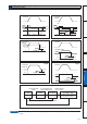
3RVLWLRQFRQWURORI0,1$6$VHULHVLVGHVFULEHGLQ%ORFNGLDJUDPRI3
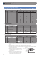
0DNHDGMXVWPHQWLQSRVLWLRQFRQWUROSHUWKHIROORZLQJSURFHGXUHV
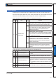
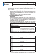
6HWXSWKHIROORZLQJSDUDPHWHUVWRWKHYDOXHVRIWKHWDEOHEHORZ
Parameter
No.
(Pr )
Parameter
No.
(Pr )
1.00
1.01
1.02
1.03
1.04
1.10
1.11
1.05
1.06
1.07
1.08
1.09
2.01
2.02
Standard
value
Title of parameter
1st gain of position loop
1st gain of velocity loop
1st time constant of velocity loop integration
1st filter of velocity detection
1st time constant of torque filter time
Velocity feed forward
Time constant of feed forward filter
2nd gain of position loop
2nd gain of velocity loop
2nd time constant of velocity loop integration
2nd filter of speed detection
2nd time constant of torque filter
1st notch frequency
1st notch width selection
0.04
0.02
2.00
2.14
2.15
2.16
2.17
1.14
1.15
1.16
1.17
1.18
1.19
2.22
2.23
Standard
value
100
0
0
0
0
0
0
0
0
0
0
0
0
1
0
Title of parameter
Inertia ratio
Setup of real time auto-gain tuning mode
Adaptive filter setup mode
1st damping frequency
Setup of 1st damping filter
2nd damping frequency
Setup of 2nd damping filter
2nd gain setup
Mode of position control switching
Delay time of position control switching delay
Level of position control switching
Hysteresis at position control switching
Position gain switching time
Positional command smoothing filter
Positional command FIR filter
270
150
370
0
152
0
0
270
150
370
0
152
5000
2
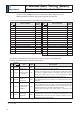
(QWHUWKHLQHUWLDUDWLRRI3U0HDVXUHWKHUDWLRRUVHWXSWKHFDOFXODWHGYDOXH
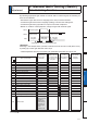
0DNHDGMXVWPHQWXVLQJWKHVWDQGDUGYDOXHVEHORZ
Order
1
2
3
4
5
Standard
value
300
50
500
250
300
Title
Parameter
No.
(Pr )
Pr1.01
Pr1.04
Pr1.00
Pr1.02
Pr1.10
1st gain of
velocity loop
1st time constant
of torque filter
1st gain of
position loop
1st time constant
of velocity loop
integration
Velocity feed
forward gain
How to adjust
Increase the value within the range where no abnormal noise and no
vibration occur. If they occur, lower the value.
When vibration occurs by changing Pr1.01, change this value.
Setup so as to make Pr1.01 x Pr1.04 becomes smaller than 10000.
If you want to suppress vibration at stopping, setup larger value to
Pr1.04 and smaller value to Pr1.01. If you experience too large
vibration right before stopping, lower than value of Pr1.04.
Adjust this observing the positioning time. Larger the setup, faster
the positioning time you can obtain, but too large setup may cause
oscillation.
Setup this value within the range where no problem occurs. If you
setup smaller value, you can obtain a shorter positioning time, but
too small value may cause oscillation. If you setup too large value,
deviation pulses do not converge and will be remained.
Increase the value within the range where no abnormal noise
occurs.
Too large setup may result in overshoot or chattering of position
complete signal, hence does not shorten the settling time. If the
command pulse is not even,you can improve by setting up Pr1.11
(Feed forward filter) to larger value.
5
4. Manual Gain Tuning (Basic)
Adjustment
Adjustment in Position Control Mode
Related page
3´'HWDLOVRISDUDPHWHUµ3´&RQWURO%ORFN'LDJUDPµ