
user manual


7-7
1
Before Using the Products
2
Preparation
3
Connection
4
Setup
5
Adjustment
6
When in Trouble
7
Supplement
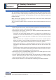
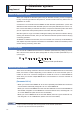
1. Safety function
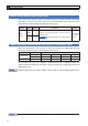
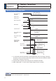
Timing Chart
Return timing from safety state
*
1 Photocouplers for safety input 1 and 2 should be turned on again with servo-on input
turned off. Otherwise, alarm occurs, and should be cleared.
Alarm clear should be performed after the safety input 1 and 2 have been turned
back to on.
Otherwise, alarm occurs.
*
2 This is an alarm condition and the dynamic brake operates according to Pr5.10 Se-
quence at alarm.
*
3 This is normal servo-off condition and the dynamic brake operates according to
Pr5.06 Sequence at servo-off.
input coupler OFF
(Servo-OFF command)
input coupler ON
(Servo-ON command)
output coupler OFF
(not ready)
output coupler ON
(ready)
output coupler OFF
(Alarm)
output coupler ON
(not Alarm)
input coupler OFF input coupler ON
output coupler OFF (Break engage)
input coupler ONinput coupler OFF
output coupler ON
generated alarm Servo-OFF
output coupler OFF
not-energized
Servo-ON input
(SEV-ON)
*1
Safety input
1
Safety input 2
Motor energization
EDM
output
Dynamic brake
Servo-Ready output
(S-RDY)
Servo-Clear intput
(ALM)
*1
Servo-Alarm output
(ALM)
External brake
release output
(BRK-OFF)
max 6ms
released/engaged
*2
released/engaged
*3
Once the servo
on command is
input, the
operation
proceeds in
synchronous
with normal
servo on/off
timing.
(Refer to P.2-61
“Timing Chart”)
Note
Related page
2QO\IRUSRVLWLRQFRQWUROW\SHLVQRWSURYLGHGZLWK;6DIHW\IXQFWLRQFRQQHFWRU
3´3Uµ3´3Uµ