
user manual

7-119
1
Before Using the Products
2
Preparation
3
Connection
4
Setup
5
Adjustment
6
When in Trouble
7
Supplement
7
7. Options
Supplement
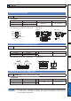
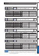
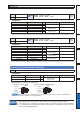
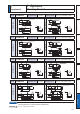
Mounting Bracket
Caution
Related page
For E, F and G-frame, you con make a front end and back end mounting by changing the
mounting direction of L-shape bracket (attachment).
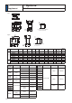
3´'LPHQVLRQVRIGULYHUµ
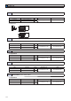
Part No.
'930
Frame symbol of
applicable driver
A-frame
Mounting screw
M4 × L6 Pan head 4pcs
Dimensions
Upper side
2-M4, Pan head
17
9.5
15
10
24
40
7
2-C5
R2
R2
11
±0.2
2.5
2.5
ø5.2
R1 or less
Bottom side
2-M4, Pan head
11
±0.2
5.2
5
40
33
17
9.5
R2
2-R1
15
10
R2
2.5
2.5
2-C5
R1 or less
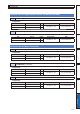
Part No.
'930
Frame symbol of
applicable driver
B-frame
Mounting screw
M4 × L6 Pan head 4pcs
Dimensions
Upper side
47
7
15
10
R2
2.5
2.5
2-M4, Pan head
24
18
±0.2
ø5.2
2-C5
17
9.5
R2
R1 or less
Bottom side
47
40
17
9.5
2.5
2.5
15
10
R2
5
18
±0.2
2-M4, Pan head
2-C5
5.2
R2
2-R1
R1 or less
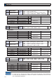
Part No.
'930
Frame symbol of
applicable driver
C-frame
Mounting screw
M4 × L6 Pan head 4pcs
Dimensions
Upper side
30
±0.2
15
10
R2
2.5
2.5
2-M4, Pan head
2-C5
17
9.5
40
20
ø5.2
R2
R1 or less
Bottom side
17
9.5
2.5
2.5
15
10
R2
30
±0.2
2-M4, Pan head
2-C5
40
20
5.2
R2
2-R1
R1 or less
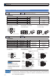
Part No.
'930
Frame symbol of
applicable driver
D-frame
Mounting screw
M4 × L6 Pan head 4pcs
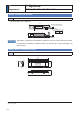
Dimensions
Upper side
36
±0.25
15
10
R2
2.5
10 40
±0.2
60
2.5
2-M4, Pan head
2-C5
17
9.5
2-ø5.2
R2
R1 or less
Bottom side
17
9.5
2.5
R1 or less
2.5
10 40
±0.2
60
36
±0.219
15
10
R2
2-M4, Pan head
2-C5
4-R1
5.2
R2
5.2